Configuring vPCs

This chapter contains the following sections:

Information About vPCs

vPC Overview

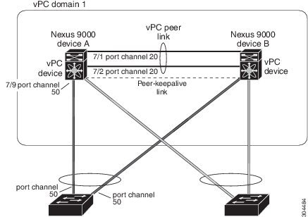
A virtual port channel (vPC) allows links that are physically connected to two Cisco Nexus devices to appear as a single port channel by a third device (see figure). The third device can be a switch, server, or any other networking device that supports port channels. A vPC can provide Layer 2 multipathing, which allows you to create redundancy and increase the bisectional bandwidth by enabling multiple parallel paths between nodes and allowing load balancing traffic.
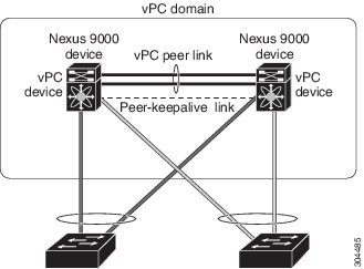
Figure 1. vPC Architecture

You can use only Layer 2 port channels in the vPC.You configure the port channels by using one of the following:

  • No protocol

  • Link Aggregation Control Protocol (LACP)

When you configure the port channels in a vPC—including the vPC peer link channel—without using LACP, each device can have up to eight active links in a single port channel. When you configure the port channels in a vPC—including the vPC peer link channels—using LACP, each device can have eight active links and eight standby links in a single port channel. (See the “vPC Interactions with Other Features” section for more information on using LACP and vPCs.)


Note


You must enable the vPC feature before you can configure or run the vPC functionality.


The system automatically takes a checkpoint prior to disabling the feature, and you can roll back to this checkpoint.

After you enable the vPC functionality, you create the peer-keepalive link, which sends heartbeat messages between the two vPC peer devices.

You can create a vPC peer link by configuring a port channel on one Cisco Nexus 3400-Schassis by using 40, 100 and 400 Gigabit Ethernet ports. To ensure that you have the correct hardware to enable and run a vPC, enter the show hardware feature-capability command. If you see an X across from the vPC in your command output, your hardware cannot enable the vPC feature.

We recommend that you configure the vPC peer link Layer 2 port channels as trunks. On another Cisco Nexus 3400-Schassis, you configure another port channel using 40, 100 and 400 Gigabit Ethernet ports in the dedicated port mode. Connecting these two port channels creates a vPC peer link in which the two linked Cisco Nexus devices appear as one device to a third device. The third device, or downstream device, can be a switch, server, or any other networking device that uses a regular port channel to connect to the vPC. If you are not using the correct module, the system displays an error message.

We recommend that you configure the vPC peer links on dedicated ports of different modules to reduce the possibility of a failure. For the best resiliency scenario, use at least two modules.

If you must configure all the vPC peer links and core-facing interfaces on a single module, you should configure a track object that is associated with the Layer 3 link to the core and on all the links on the vPC peer link on both vPC peer devices. Once you configure this feature and if the primary vPC peer device fails, the system automatically suspends all the vPC links on the primary vPC peer device. This action forces all the vPC traffic to the secondary vPC peer device until the system stabilizes.

You can create a track object and apply that object to all links on the primary vPC peer device that connect to the core and to the vPC peer link. See the Cisco Nexus 3400-S NX-OS Unicast Routing Configuration Guide for information about the track interface command.

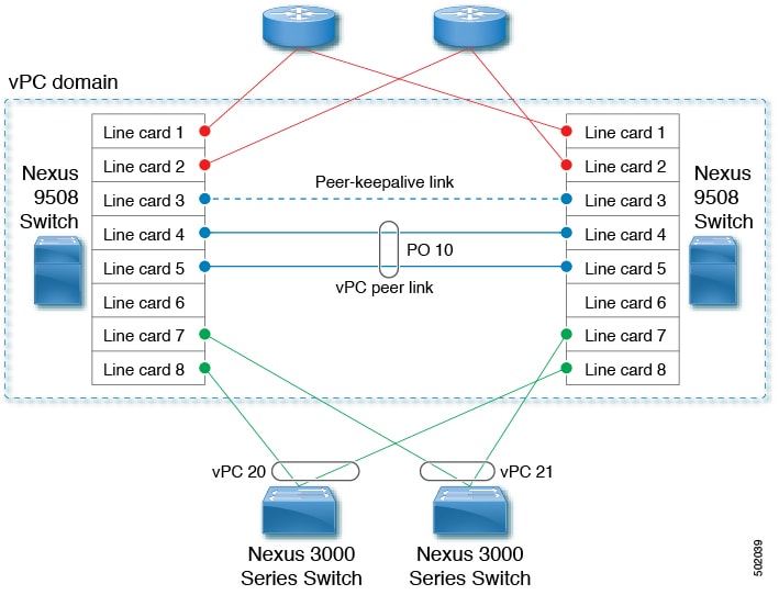
The vPC domain includes both vPC peer devices, the vPC peer-keepalive link, the vPC peer link, and all of the port channels in the vPC domain connected to the downstream device. You can have only one vPC domain ID on each device.

In this version, you can connect each downstream device to a single vPC domain ID using a single port channel.


Note


Always attach all vPC devices using port channels to both vPC peer devices.


A vPC (see figure) provides the following benefits:

  • Allows a single device to use a port channel across two upstream devices

  • Eliminates Spanning Tree Protocol (STP) blocked ports

  • Provides a loop-free topology

  • Uses all available uplink bandwidth

  • Provides fast convergence if either the link or a device fails

  • Provides link-level resiliency

  • Assures high availability

Figure 2. vPC Interfaces

Hitless vPC Role Change

A virtual port channel (vPC) allows links that are physically connected to two different Cisco Nexus 3400-S devices to appear as a single port channel. The vPC role change feature enables you switch vPC roles between vPC peers without impacting traffic flow. The vPC role switching is done based on the role priority value of the device under the vPC domain. A vPC peer device with lower role priority is selected as the primary vPC device during the vPC Role switch. You can use the vpc role preempt command to switch vPC role between peers.

vPC Terminology

The terminology used in vPCs is as follows: 

  •  vPC—The combined port channel between the vPC peer devices and the downstream device. 

  •  vPC peer device—One of a pair of devices that are connected with the special port channel known as the vPC peer link. 

  •  vPC peer link—The link used to synchronize states between the vPC peer devices. Both ends must be on 10-Gigabit Ethernet or 40-Gigabit Ethernet interfaces. 

  • vPC member port—An interface that belongs to a vPC. 

  • Host vPC port—A Fabric Extender host interfaces that belongs to a vPC. 

  • vPC domain—This domain includes both vPC peer devices, the vPC peer-keepalive link, and all of the port channels in the vPC connected to the downstream devices. It is also associated to the configuration mode that you must use to assign vPC global parameters. 

  • vPC peer-keepalive link—The peer-keepalive link monitors the vitality of a vPC peer Cisco Nexus 3400-Sdevice. The peer-keepalive link sends configurable, periodic keepalive messages between vPC peer devices. 

    We recommend that you associate a peer-keepalive link to a separate virtual routing and forwarding (VRF) instance that is mapped to a Layer 3 interface in each vPC peer device. If you do not configure a separate VRF, the system uses the management VRF by default. However, if you use the management interfaces for the peer-keepalive link, you must put a management switch connected to both the active and standby management ports on each vPC peer device (see figure). 

    Figure 3. Separate Switch Required to Connect Management Ports for vPC Peer-Keepalive Link
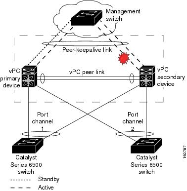
    No data or synchronization traffic moves over the vPC peer-keepalive link; the only traffic on this link is a message that indicates that the originating switch is operating and running a vPC. 

  • vPC member port—Interfaces that belong to the vPCs. 

  • Dual-active— Both vPC peers act as primary. This situation occurs when the peer-keepalive and peer-link go down when both the peers are still active. In this case, the secondary vPC assumes that the primary vPC is inactive and acts as the primary vPC. 

  • Recovery—When the peer-keepalive and the peer-link come up, one switch becomes the secondary vPC. On the switch that becomes the secondary vPC, the vPC links go down and come back up. 

vPC Peer Link Overview

You can have only two devices as vPC peers; each device can serve as a vPC peer to only one other vPC peer. The vPC peer devices can also have non-vPC links to other devices. 

See the following figure for invalid vPC peer configurations. 
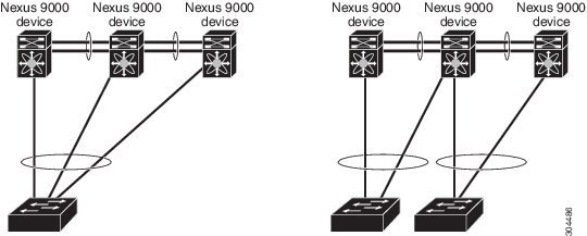
Figure 4. vPC Peer Configurations That Are Not Allowed

To make a valid configuration, you first configure a port channel on each device and then configure the vPC domain. You assign the port channel on each device as a peer link, using the same vPC domain ID. For redundancy, we recommend that you should configure at least two of the dedicated ports into the port channel because if one of the interfaces in the vPC peer link fails, the device automatically falls back to use another interface in the peer link. 


Note


We recommend that you configure the Layer 2 port channels in trunk mode. 


Many operational parameters and configuration parameters must be the same in each device connected by a vPC peer link (see the “Compatibility Parameters for vPC Interfaces” section). Because each device is completely independent on the management plane, you must ensure that the devices are compatible on the critical parameters. vPC peer devices have separate control planes. After configuring the vPC peer link, you should display the configuration on each vPC peer device to ensure that the configurations are compatible. 


Note


You must ensure that the two devices connected by the vPC peer link have certain identical operational and configuration parameters. For more information on required configuration consistency, see the “Compatibility Parameters for vPC Interfaces” section. 


When you configure the vPC peer link, the vPC peer devices negotiate that one of the connected devices is the primary device and the other connected device is the secondary device (see the “Configuring vPCs” section). The Cisco NX-OS software uses the lowest MAC address to elect the primary device. The software takes different actions on each device—that is, the primary and secondary—only in certain failover conditions. If the primary device fails, the secondary device becomes the new primary device when the system recovers, and the previously primary device is now the secondary device. 

You can also configure which of the vPC devices is the primary device. Changing the priority of the vPC peer devices can cause the interfaces in your network to go up and down. If you want to configure the role priority again to make one vPC device the primary device, configure the role priority on both the primary vPC device with a lower priority value and the secondary vPC device with the higher value. Then, shut down the port channel that is the vPC peer link on both devices by entering the  shutdown  command, and finally reenable the port channel on both devices by entering the  no shutdown  command. 


Note


We recommend that you use two different modules for redundancy on each vPC peer device on each vPC peer link. 


The software keeps all traffic that forwards across the vPC peer devices as local traffic. A packet that ingresses the port channel uses one of the local links rather than moving across the vPC peer link. Unknown unicast, multicast, and broadcast traffic (including STP BPDUs) are flooded across the vPC peer link. The software keeps the multicast forwarding state synchronized on both of the vPC peer devices. 

You can configure any of the standard load-balancing schemes on both the vPC peer link devices and the downstream device (see the “Configuring Port Channels” chapter for information about load balancing). 

Configuration information flows across the vPC peer links using the Cisco Fabric Services over Ethernet (CFSoE) protocol. (See the “vPC and Orphan Ports” section for more information about CFSoE.) 

All MAC addresses for those VLANs configured on both devices are synchronized between vPC peer devices. The software uses CFSoE for this synchronization. (See the “vPC and Orphan Ports” section for information about CFSoE.) 

If the vPC peer link fails, the software checks the status of the remote vPC peer device using the peer-keepalive link, which is a link between vPC peer devices that ensures that both devices are up. If the vPC peer device is up, the secondary vPC device disables all vPC ports on its device, to prevent loops and disappearing or flooding traffic. The data then forwards down the remaining active links of the port channel. 


Note


 We recommend that you create and configure a separate VRF and configure a Layer 3 port on each vPC peer device in that VRF for the vPC peer-keepalive link. The default ports and VRF for the peer-keepalive are the management ports and VRF. 


The software learns of a vPC peer device failure when the keepalive messages are not returned over the peer-keepalive link. 

Use a separate link (vPC peer-keepalive link) to send configurable keepalive messages between the vPC peer devices. The keepalive messages on the vPC peer-keepalive link determines whether a failure is on the vPC peer link only or on the vPC peer device. The keepalive messages are used only when all the links in the peer link fail. See the “Peer-Keepalive Link and Messages” section for information about the keepalive message. 

Features That You Must Manually Configure on the Primary and Secondary Devices

You must manually configure the following features to conform to the primary/secondary mapping of each of the vPC peer devices:

  • STP root—Configure the primary vPC peer device as the STP primary root device and configure the vPC secondary device to be the STP secondary root device. See the “vPC Peer Links and STP” section for more information about vPCs and STP.

    • We recommend that you configure the vPC peer link interfaces as STP network ports so that Bridge Assurance is enabled on all vPC peer links.

    • We recommend that you configure Rapid per VLAN Spanning Tree plus (PVST+) so that the primary device is the root for all VLANs and configure Multiple Spanning Tree (MST) so that the primary device is the root for all instances.

  • Layer 3 VLAN network interface—Configure Layer 3 connectivity from each vPC peer device by configuring a VLAN network interface for the same VLAN from both devices.

  • HSRP active—If you want to use Hot Standby Router Protocol (HSRP) and VLAN interfaces on the vPC peer devices, configure the primary vPC peer device with the HSRP active highest priority. Configure the secondary device to be the HSRP standby and ensure that you have VLAN interfaces on each vPC device that are in the same administrative and operational mode. (See the “vPC Peer Links and Routing” section for more information on vPC and HSRP.)

While you configure Unidirectional Link Detection (UDLD), note the following recommendations:

  • If LACP is used as port-channel aggregation protocol, UDLD is not required in a vPC domain.

  • If LACP is not used as the port-channel aggregation protocol (static port-channel), use UDLD in normal mode on vPC member ports.

  • If STP is used without Bridge Assurance and if LACP is not used, use UDLD in normal mode on vPC orphan ports.

Configuring Layer 3 Backup Routes on a vPC Peer Link

You can use VLAN network interfaces on the vPC peer devices to link to Layer 3 of the network for such applications as HSRP. Ensure that you have a VLAN network interface configured on each peer device and that the interface is connected to the same VLAN on each device. Also, each VLAN interface must be in the same administrative and operational mode. For more information about configuring VLAN network interfaces, see the “Configuring Layer 3 Interfaces” chapter.

If a failover occurs on the vPC peer link, the VLAN interfaces on the vPC peer devices are also affected. If a vPC peer link fails, the system brings down associated VLAN interfaces on the secondary vPC peer device.

You can ensure that specified VLAN interfaces do not go down on the vPC secondary device when the vPC peer link fails.

Use the dual-active exclude interface-vlan command to configure this feature.

Peer-Keepalive Link and Messages

The Cisco NX-OS software uses the peer-keepalive link between the vPC peers to transmit periodic, configurable keepalive messages. You must have Layer 3 connectivity between the peer devices to transmit these messages; the system cannot bring up the vPC peer link unless the peer-keepalive link is already up and running.


Note


We recommend that you associate the vPC peer-keepalive link to a separate VRF mapped to a Layer 3 interface in each vPC peer device. If you do not configure a separate VRF, the system uses the management VRF and management ports by default. Do not use the peer link itself to send and receive vPC peer-keepalive messages.


If one of the vPC peer devices fails, the vPC peer device on the other side of the vPC peer link senses the failure by not receiving any peer-keepalive messages. The default interval time for the vPC peer-keepalive message is 1 second, and you can configure the interval between 400 milliseconds and 10 seconds.

You can configure a hold-timeout value with a range of 3 to 10 seconds; the default hold-timeout value is 3 seconds. This timer starts when the vPC peer link goes down. During this hold-timeout period, the secondary vPC peer device ignores vPC peer-keepalive messages, which ensures that network convergence occurs before a vPC action takes place. The purpose of the hold-timeout period is to prevent false-positive cases.

You can also configure a timeout value with a range of 3 to 20 seconds; the default timeout value is 5 seconds. This timer starts at the end of the hold-timeout interval. During the timeout period, the secondary vPC peer device checks for vPC peer-keepalive hello messages from the primary vPC peer device. If the secondary vPC peer device receives a single hello message, that device disables all vPC interfaces on the secondary vPC peer device.

The difference between the hold-timeout and the timeout parameters is as follows:

  • During the hold-timeout, the vPC secondary device does not take any action based on any keepalive messages received, which prevents the system taking action when the keepalive might be received just temporarily, such as if a supervisor fails a few seconds after the peer link goes down.

  • During the timeout, the vPC secondary device takes action to become the vPC primary device if no keepalive message is received by the end of the configured interval.

See the “Configuring vPCs” section for information about configuring the timer for the keepalive messages.


Note


Ensure that both the source and destination IP addresses used for the peer-keepalive messages are unique in your network and these IP addresses are reachable from the VRF associated with the vPC peer-keepalive link.


Use the command-line interface (CLI) to configure the interfaces you are using the vPC peer-keepalive messages as trusted ports. Leave the precedence at the default (6) or configure it higher. The following is an example of configuring an interface as a trusted port:


(config)# class-map type qos match-all trust-map
(config-cmap-qos)# match cos 4-7
(config)# policy-map type qos ingresspolicy
(config-pmap-qos)# class trust-map
(config)# interface Ethernet 8/11
(config-if)# service-policy type qos input ingresspolicy

vPC Peer-Gateway

You can configure vPC peer devices to act as the gateway even for packets that are destined to the vPC peer device’s MAC address.

Use the peer-gateway command to configure this feature.


Note


The peer-gateway exclude-vlan command that is used when configuring a VLAN interface for Layer 3 backup routing on vPC peer devices is not supported.


Some network-attached storage (NAS) devices or load balancers might have features that help to optimize the performances of particular applications. These features enable the device to avoid a routing-table lookup when responding to a request that originated from a host that is not locally attached to the same subnet. Such devices might reply to traffic using the MAC address of the sender Cisco Nexus 3400-S device rather than the common HSRP gateway. This behavior is noncomplaint with some basic Ethernet RFC standards. Packets that reach a vPC device for the nonlocal router MAC address are sent across the peer link and could be dropped by the built in vPC loop avoidance mechanism if the final destination is behind another vPC.

The vPC peer-gateway capability allows a vPC switch to act as the active gateway for packets that are addressed to the router MAC address of the vPC peer. This feature enables local forwarding of packets without the need to cross the vPC peer link. In this scenario, the feature optimizes use of the peer link and avoids potential traffic loss.

Configuring the peer-gateway feature must be done on both primary and secondary vPC peers and is nondisruptive to the operations of the device or to the vPC traffic. The vPC peer-gateway feature can be configured globally under the vPC domain submode.

When you enable this feature, Cisco NX-OS automatically disables IP redirects on all interface VLANs mapped over a vPC VLAN to avoid generation of IP redirect messages for packets switched through the peer gateway router.

Packets that arrive at the peer-gateway vPC device have their Time to Live (TTL) decremented, so that packets carrying a TTL of 1 might get dropped in transit due to TTL expiration. You should take this situation into account when the peer-gateway feature is enabled and particular network protocols that source packets with a TTL of 1 operate on a vPC VLAN.

vPC Domain

You can use the vPC domain ID to identify the vPC peer links and the ports that are connected to the vPC downstream devices.

The vPC domain is also a configuration mode that you use to configure the keepalive messages and other vPC peer link parameters rather than accept the default values. See the “Configuring vPCs” section for more information about configuring these parameters.

To create a vPC domain, you must first create a vPC domain ID on each vPC peer device using a number from 1 to 1000. You can have only one vPC domain per vPC peer.

You must explicitly configure the port channel that you want to act as the peer link on each device. You associate the port channel that you made a peer link on each device with the same vPC domain ID to form a single vPC domain. Within this domain, the system provides a loop-free topology and Layer 2 multipathing.

You can only configure these port channels and vPC peer links statically. All ports in the vPC on each of the vPC peer devices must be in the same VDC. You can configure the port channels and vPC peer links either using LACP or no protocol. We recommend that you use LACP with the interfaces in active mode to configure port channels in each vPC, which ensures an optimized, graceful recovery in a port-channel failover scenario and provides configuration checks against configuration mismatches among the port channels themselves.

The vPC peer devices use the vPC domain ID that you configure to automatically assign a unique vPC system MAC address. Each vPC domain has a unique MAC address that is used as a unique identifier for the specific vPC-related operations, although the devices use the vPC system MAC addresses only for link-scope operations, such as LACP. We recommend that you create each vPC domain within the contiguous Layer 2 network with a unique domain ID. You can also configure a specific MAC address for the vPC domain, rather than having the Cisco NX-OS software assign the address.

See the “vPC and Orphan Ports” section for more information about displaying the vPC MAC table.

After you create a vPC domain, the Cisco NX-OS software creates a system priority for the vPC domain. You can also configure a specific system priority for the vPC domain.


Note


When manually configuring the system priority, you must ensure that you assign the same priority value on both vPC peer devices. If the vPC peer devices have different system priority values, vPC does not come up.


vPC Topology

The following figure shows a basic configuration in which the Cisco Nexusdevice ports are directly connected to another switch or host and are configured as part of a port channel that becomes part of a vPC. 
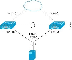
Figure 5. Switch vPC Topology

In the figure, vPC 20 is configured on port channel 20, which has Eth1/10 on the first device and Eth2/1 on the second as member ports. 

Compatibility Parameters for vPC Interfaces

Many configuration and operational parameters must be identical on all interfaces in the vPC. We recommend that you configure the Layer 2 port channels that you use for the vPC peer link in trunk mode.

After you enable the vPC feature and configure the peer link on both vPC peer devices, Cisco Fabric Services (CFS) messages provide a copy of the configuration on the local vPC peer device configuration to the remote vPC peer device. The system then determines whether any of the crucial configuration parameters differ on the two devices. (See the “vPC and Orphan Ports” section for more information about CFS.)


Note


Enter the show vpc consistency-parameters command to display the configured values on all interfaces in the vPC. The displayed configurations are only those configurations that would limit the vPC peer link and vPC from coming up.


The compatibility check process for vPCs differs from the compatibility check for regular port channels.

See the “Configuring Port Channels” chapter for information about regular port channels.

Configuration Parameters That Must Be Identical

The configuration parameters in this section must be configured identically on both devices of the vPC peer link; otherwise, the vPC moves fully or partially into a suspended mode.


Note


You must ensure that all interfaces in the vPC have the identical operational and configuration parameters listed in this section.


Note


Enter the show vpc consistency-parameters command to display the configured values on all interfaces in the vPC. The displayed configurations are only those configurations that would limit the vPC peer link and vPC from coming up.


The devices automatically check for compatibility for some of these parameters on the vPC interfaces. The per-interface parameters must be consistent per interface, and the global parameters must be consistent globally:

  • Port-channel mode: on, off, or active (port-channel mode can, however, be active/passive on each side of the vPC peer)

  • Link speed per channel

  • Duplex mode per channel

  • Trunk mode per channel:

    • Native VLAN

    • VLANs allowed on trunk

    • Tagging of native VLAN traffic

  • Spanning Tree Protocol (STP) mode

  • STP region configuration for Multiple Spanning Tree

  • Enable/disable state per VLAN

  • STP global settings:

    • Bridge Assurance setting

    • Port type setting

    • Loop Guard settings

  • STP interface settings:

    • Port type setting

    • Loop Guard

    • Root Guard

  • Maximum Transmission Unit (MTU)

If any of these parameters are not enabled or defined on either device, the vPC consistency check ignores those parameters.


Note


To ensure that none of the vPC interfaces are in the suspend mode, enter the show vpc brief and show vpc consistency-parameters commands and check the syslog messages.


Configuration Parameters That Should Be Identical

When any of the following parameters are not configured identically on both vPC peer devices, a misconfiguration might cause undesirable behavior in the traffic flow:

  • MAC aging timers

  • Static MAC entries

  • VLAN interface—Each device on the end of the vPC peer link must have a VLAN interface configured for the same VLAN on both ends and they must be in the same administrative and operational mode. Those VLANs configured on only one device of the peer link do not pass traffic using the vPC or peer link. You must create all VLANs on both the primary and secondary vPC devices, or the VLAN will be suspended.

  • All ACL configurations and parameters

  • Quality of Service (QoS) configuration and parameters

  • STP interface settings:

    • BPDU Filter

    • BPDU Guard

    • Cost

    • Link type

    • Priority

    • VLANs (Rapid PVST+)

  • Port security

  • Cisco Trusted Security (CTS)

  • Dynamic Host Configuration Protocol (DHCP) snooping

  • Network Access Control (NAC)

  • Dynamic ARP Inspection (DAI)

  • IP source guard (IPSG)

  • Internet Group Management Protocol (IGMP) snooping

  • Hot Standby Routing Protocol (HSRP)

  • All routing protocol configurations

To ensure that all the configuration parameters are compatible, we recommend that you display the configurations for each vPC peer device once you configure the vPC.

Consequences of Parameter Mismatches

You can configure the graceful consistency check feature, which suspends only the links on the secondary peer device when a mismatch is introduced in a working vPC. This feature is configurable only in the CLI and is enabled by default.

Use the graceful consistency-check command to configure this feature.

As part of the consistency check of all parameters from the list of parameters that must be identical, the system checks the consistency of all VLANs.

The vPC remains operational, and only the inconsistent VLANs are brought down. This per-VLAN consistency check feature cannot be disabled and does not apply to Multiple Spanning Tree (MST) VLANs.

vPC Number

Once you have created the vPC domain ID and the vPC peer link, you create port channels to attach the downstream device to each vPC peer device. That is, you create one port channel to the downstream device from the primary vPC peer device and you create another port channel to the downstream device from the secondary peer device.


Note


We recommend that you configure the ports on the downstream devices that connect to a host or a network device that is not functioning as a switch or a bridge as STP edge ports.


On each vPC peer device, you assign a vPC number to the port channel that connects to the downstream device. You will experience minimal traffic disruption when you are creating vPCs. To simplify the configuration, you can assign the vPC ID number to every port channel to be the same as the port channel itself (that is, vPC ID 10 for port channel 10).


Note


The vPC number that you assign to the port channel that connects to the downstream device from the vPC peer device must be identical on both vPC peer devices.


Moving Other Port Channels into a vPC


Note


You must attach a downstream device using a port channel to both vPC peer devices.


To connect to the downstream device, you create a port channel to the downstream device from the primary vPC peer device and you create another port channel to the downstream device from the secondary peer device. On each vPC peer device, you assign a vPC number to the port channel that connects to the downstream device. You will experience minimal traffic disruption when you are creating vPCs.

Configuring vPC Peer Links and Links to the Core on a Single Module


Note


We recommend that you configure the vPC peer links on dedicated ports of different modules to reduce the possibility of a failure. For the best resiliency scenario, use at least two modules.


If you must configure all the vPC peer links and core-facing interfaces on a single module, you should configure, using the command-line interface, a track object and a track list that is associated with the Layer 3 link to the core and on all vPC peer links on both vPC peer devices. You use this configuration to avoid dropping traffic if that particular module goes down because when all the tracked objects on the track list go down, the system does the following:

  • Stops the vPC primary peer device sending peer-keepalive messages, which forces the vPC secondary peer device to take over.

  • Brings down all the downstream vPCs on that vPC peer device, which forces all the traffic to be rerouted in the access switch toward the other vPC peer device.

Once you configure this feature and if the module fails, the system automatically suspends all the vPC links on the primary vPC peer device and stops the peer-keepalive messages. This action forces the vPC secondary device to take over the primary role and all the vPC traffic to go to this new vPC primary device until the system stabilizes.

You should create a track list that contains all the links to the core and all the vPC peer links as its object. Enable tracking for the specified vPC domain for this track list. Apply this same configuration to the other vPC peer device. See the Cisco Nexus 3400-S NX-OS Unicast Routing Configuration Guide for information about configuring object tracking and track lists.


Note


This example uses Boolean OR in the track list and forces all traffic to the vPC peer device only for a complete module failure. If you want to trigger a switchover when any core interface or peer link goes down, use a Boolean AND in the torack list below.


To configure a track list to switch over a vPC to the remote peer when all related interfaces on a single module fail, follow these steps:

  1. Configure track objects on an interface (Layer 3 to core) and on a port channel (vPC peer link).

    
    switch(config-if)# track 35 interface ethernet 8/35 line-protocol
    switch(config-track)# track 23 interface ethernet 8/33 line-protocol
    switch(config)# track 55 interface port-channel 100 line-protocol
    
    
  2. Create a track list that contains all the interfaces in the track list using the Boolean OR to trigger when all objects fail.

    
    switch(config)# track 44 list boolean OR
    switch(config-track)# object 23
    switch(config-track)# object 35
    switch(config-track)# object 55
    switch(config-track)# end
    
    
  3. Add this track object to the vPC domain:

    
    switch(config)# vpc domain 1
    switch(config-vpc-domain)# track 44
    
    
  4. Display the track object:

    
    switch# show vpc brief
    Legend:
    (*) - local vPC is down, forwarding via vPC peer-link
    vPC domain id : 1
    Peer status : peer adjacency formed ok
    vPC keep-alive status : peer is alive
    Configuration consistency status: success
    vPC role : secondary
    Number of vPCs configured : 52
    Track object : 44
    vPC Peer-link status
    ---------------------------------------------------------------------
    id Port Status Active vlans
    -- ---- ------ --------------------------------------------------
    1 Po100 up 1-5,140
    vPC status
    ----------------------------------------------------------------------
    id Port Status Consistency Reason Active vlans
    -- ---- ------ ----------- -------------------------- ------------
    1 Po1 up success success 1-5,140


This example shows how to display information about the track objects:


switch# show track brief
Track Type Instance Parameter State Last
Change
23 Interface Ethernet8/33 Line Protocol UP 00:03:05
35 Interface Ethernet8/35 Line Protocol UP 00:03:15
44 List ----- Boolean
or UP 00:01:19
55 Interface port-channel100 Line Protocol UP 00:00:34

vPC Interactions with Other Features

vPC and LACP

LACP uses the system MAC address of the vPC domain to form the LACP Aggregation Group (LAG) ID for the vPC. (See the “Configuring Port Channels” chapter for information about LAG-ID and LACP.)

You can use LACP on all the vPC port channels, including those channels from the downstream device. We recommend that you configure LACP with active mode on the interfaces on each port channel on the vPC peer devices. This configuration allows you to more easily detect compatibility between devices, unidirectional links, and multihop connection, and provides dynamic reaction to run-time changes and link failures.

We recommend that you manually configure the system priority on the vPC peer link devices to ensure that the vPC peer link devices have a higher LACP priority than the downstream connected devices. A lower numerical value system priority means a higher LACP priority.


Note


When manually configuring the system priority, you must ensure that you assign the same priority value on both vPC peer devices. If the vPC peer devices have different system priority values, vPC does not come up.


vPC Peer Links and STP

Although vPCs provide a loop-free Layer 2 topology, STP is still required to provide a fail-safe mechanism to protect against any incorrect or defective cabling or possible misconfiguration. When you first bring up a vPC, STP reconverges. STP treats the vPC peer link as a special link and always includes the vPC peer link in the STP active topology.

We recommend that you set all the vPC peer link interfaces to the STP network port type so that Bridge Assurance is automatically enabled on all vPC peer links. We also recommend that you do not enable any of the STP enhancement features on vPC peer links. If the STP enhancements are already configured, they do not cause any problems for the vPC peer links..

When you are running both MST and Rapid PVST+, ensure that the PVST simulation feature is correctly configured.

See the Cisco Nexus 3400-S NX-OS Layer 2 Switching Configuration Guide for information about STP enhancement features and PVST simulation.


Note


You must configure a list of parameters to be identical on the vPC peer devices on both sides of the vPC peer link. See the “Compatibility Parameters for vPC Interfaces” section for information about these required matched settings.


STP is distributed; that is, the protocol continues running on both vPC peer devices. However, the configuration on the vPC peer device elected as the primary device controls the STP process for the vPC interfaces on the secondary vPC peer device.

The primary vPC device synchronizes the STP state on the vPC secondary peer device using Cisco Fabric Services over Ethernet (CFSoE). See the “vPC and Orphan Ports” section for information about CFSoE.

The STP process for vPC also relies on the periodic keepalive messages to determine when one of the connected devices on the peer link fails. See the “Peer-Keepalive Link and Messages” section for information about these messages.

The vPC manager performs a proposal/handshake agreement between the vPC peer devices that set the primary and secondary devices and coordinates the two devices for STP. The primary vPC peer device then controls the STP protocol on both the primary and secondary devices. We recommend that you configure the primary vPC peer device as the STP primary root device and configure the secondary VPC device to be the STP secondary root device.

If the primary vPC peer device fails over to the secondary vPC peer device, there is no change in the STP topology.

The BPDUs uses the MAC address set for the vPC for the STP bridge ID in the designated bridge ID field. The vPC primary device sends these BPDUs on the vPC interfaces.

You must configure both ends of vPC peer link with the identical STP configuration for the following parameters:

  • STP global settings:

    • STP mode

    • STP region configuration for MST

    • Enable/disable state per VLAN

    • Bridge Assurance setting

    • Port type setting

    • Loop Guard settings

  • STP interface settings:

    • Port type setting

    • Loop Guard

    • Root Guard


Note


If any of these parameters are misconfigured, the Cisco NX-OS software suspends all interfaces in the vPC. Check the syslog and enter the show vpc brief command to see if the vPC interfaces are suspended.


Ensure that the following STP interface configurations are identical on both sides of the vPC peer links or you may see unpredictable behavior in the traffic flow:

  • BPDU Filter

  • BPDU Guard

  • Cost

  • Link type

  • Priority

  • VLANs (PVRST+)


Note


Display the configuration on both sides of the vPC peer link to ensure that the settings are identical.


You can use the show spanning-tree command to display information about the vPC when that feature is enabled. See the Cisco Nexus 3400-S NX-OS Layer 2 Switching Configuration Guide for an example.


Note


We recommend that you configure the ports on the downstream devices as STP edge ports. You should configure all host ports connected to a switch as STP edge ports. See the Cisco Nexus 3400-S NX-OS Layer 2 Switching Configuration Guide for more information about STP port types.


vPC Peer Switch

The vPC peer switch feature was added to Cisco NX-OS to address performance concerns around STP convergence. This feature allows a pair of Cisco Nexus 3400-S devices to appear as a single STP root in the Layer 2 topology. This feature eliminates the need to pin the STP root to the vPC primary switch and improves vPC convergence if the vPC primary switch fails.

To avoid loops, the vPC peer link is excluded from the STP computation. In vPC peer switch mode, STP BPDUs are sent from both vPC peer devices to avoid issues related to STP BPDU timeout on the downstream switches, which can cause traffic disruption.

This feature can be used with the pure peer switch topology in which the devices all belong to the vPC.


Note


Peer-switch feature is supported on networks that use vPC and STP-based redundancy is not supported. If the vPC peer-link fail in a hybrid peer-switch configuration, you can lose traffic. In this scenario, the vPC peers use the same STP root ID as well as the same bridge ID. The access switch traffic is split in two with half going to the first vPC peer and the other half to the second vPC peer. With peer link failure, there is no impact to the north/south traffic but the east/west traffic is lost.


See the Cisco Nexus 3400-S NX-OS Layer 2 Switching Configuration Guide for information about STP enhancement features and Rapid PVST+.

vPC and ARP or ND

A feature was added to Cisco NX-OS to address table synchronization across vPC peers using the reliable transport mechanism of the Cisco Fabric Service over Ethernet (CFSoE) protocol. You must enable the ip arp synchronize and ipv6 nd synchronize commands to support faster convergence of address tables between the vPC peers. This convergence overcomes the delay that occurs in ARP table restoration for IPv4 or ND table restoration for IPv6 when the peer link port channel flaps or when a vPC peer comes back online.

vPC Peer Links and Routing

The First Hop Redundancy Protocols (FHRPs) interoperate with vPCs. The Hot Standby Routing Protocol (HSRP), and Virtual Router Redundancy Protocol (VRRP) all interoperate with vPCs. We recommend that you dual-attach all Layer 3 devices to both vPC peer devices.

The primary FHRP device responds to ARP requests, even though the secondary vPC device forwards the data traffic.

To simplify initial configuration verification and vPC/HSRP troubleshooting, you can configure the primary vPC peer device with the FHRP active router highest priority.

In addition, you can use the priority command in the if-hsrp configuration mode to configure failover thresholds for when a group state enabled on a vPC peer link is in standby or in listen state. You can configure lower and upper thresholds to prevent the interface from going up and down.

VRRP acts similarly to HSRP when running on vPC peer devices. You should configure VRRP the same way that you configure HSRP.

When the primary vPC peer device fails over to the secondary vPC peer device, the FHRP traffic continues to flow seamlessly.

We recommend that you configure routing adjacency between the two vPC peer devices to act as a backup routing path. If one vPC peer device loses Layer 3 uplinks, the vPC can redirect the routed traffic to the other vPC peer device and leverage its active Layer 3 uplinks.

You can configure the inter-switch link for a backup routing path in the following ways:

  • Create a Layer 3 link between the two vPC peer devices.

  • Use the non-VPC VLAN trunk with a dedicated VLAN interface.

  • Use a vPC peer link with a dedicated VLAN interface.

We do not recommend that you configure the burnt-in MAC address option (use-bia) for HSRP or manually configure virtual MAC addresses for any FHRP protocol in a vPC environment because these configurations can adversely affect vPC load balancing. The HSRP use-bia option is not supported on vPCs. When you are configuring custom MAC addresses, you must configure the same MAC address on both vPC peer devices.

You can use the delay restore command to configure a restore timer that delays the vPC coming back up until after the peer adjacency forms and the VLAN interfaces are back up. This feature enables you to avoid packet drops when the routing tables might not be converged before the vPC is once again passing traffic. Use the delay restore command to configure this feature.

To delay the VLAN interfaces on the restored vPC peer device from coming up, use the interfaces-vlan option of the delay restore command.

Best Practices for Layer 3 and vPC Configuration

This section describes best practices for using and configuring Layer 3 with vPC.

 Layer 3 and vPC Configuration Overview

When a Layer 3 device is connected to a vPC domain through a vPC, it has the following views: 

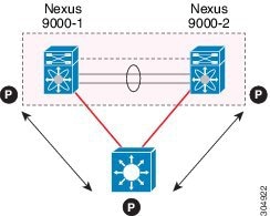
  • At Layer 2, the Layer 3 device sees a unique Layer 2 switch presented by the vPC peer devices. 

  • At Layer 3, the Layer 3 device sees two distinct Layer 3 devices (one for each vPC peer device). 

vPC is a Layer 2 virtualization technology, so at Layer 2, both vPC peer devices present themselves as a unique logical device to the rest of the network. 

There is no virtualization technology at Layer 3, so each vPC peer device is seen as a distinct Layer 3 device by the rest of the network. 

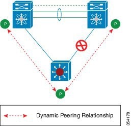
The following figure illustrates the two different Layer 2 and Layer 3 views with vPC. 
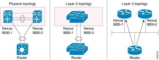
Figure 6. Different Views for vPC Peer Devices
Guidelines for Layer 3 and vPC Configurations

To connect Layer 3 devices to a vPC domain, use Layer 3 links from Layer 3 devices to connect each vPC peer device. 


Note


The vPC loop avoidance rule does not allow the attachment of a Layer 3 device to a vPC domain using a vPC. 


 Layer 3 devices are able to initiate Layer 3 routing protocol adjacencies with both vPC peer devices. 

OSPF and BGP routing protocols are supported.

One or multiple Layer 3 links can be used to connect a Layer 3 device to each vPC peer device. Cisco Nexus 3400-Sdevices support Layer 3 Equal Cost Multipathing (ECMP) with up to 16 hardware load-sharing paths per prefix. Traffic from a vPC peer device to a Layer 3 device can be load-balanced across all the Layer 3 links interconnecting the two devices together. 

Using Layer 3 ECMP on the Layer 3 device can effectively use all Layer 3 links from the device to the vPC domain. Traffic from a Layer 3 device to the vPC domain can be load-balanced across all the Layer 3 links interconnecting the two entities together. 

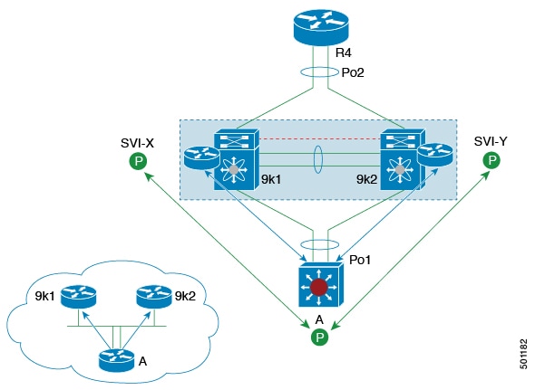
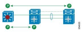
The supported connection model for a Layer 3 device to the vPC domain is illustrated in the following figure. 
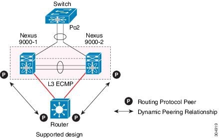
Figure 7. Using Separate Layer 3 Links to Connect L3 Device to a vPC Domain

Follow these guidelines when connecting a Layer 3 device to the vPC domain: 

  • Use separate Layer 3 links to connect Layer 3 devices to the vPC domain. 

  • Do not use a Layer 2 vPC to attach a Layer 3 device to a vPC domain unless the Layer 3 device can statically route to the HSRP address configured on the vPC peer devices. 

  • When both routed and bridged traffic are required, use individual Layer 3 links for routed traffic and a separate Layer 2 port-channel for bridged traffic when both routed and bridged traffic are required. 

  • Enable Layer 3 connectivity between vPC peer device by configuring a VLAN network interface for the same VLAN from both devices or by using a dedicated Layer 3 link between the two peer devices (for Layer 3 backup routing path purposes). 

  • The supported routing protocols are OSPF and BGP.

Example Topologies for Layer 3 and vPC

This section contains examples of network topologies for Layer 3 and vPC. 
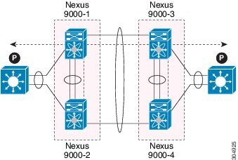
Figure 8. Legend


Peering Between Routers

In this example, vPC is used as a Layer 2 transit path. Because there is no direct routing protocol peering adjacency from the Layer 3 device to any vPC peer device, this topology is supported. 
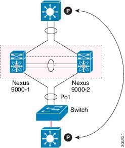
Figure 9. Peering Between Routers


Peering with an External Router Using Layer 3 Links

This example shows a topology that uses Layer 3 links to connect a Layer 3 device to the vPC domain. 


Note


Interconnecting the 2 entities together in this way is a best practice. 


Figure 10. Peering with an External Router Using Layer 3 Links
Peering Between vPC Devices for a Backup Routing Path

This example shows peering between the two vPC peer devices with a Layer 3 backup routed path. If the Layer 3 uplinks on vPC peer device 1 or vPC peer device 2 fail, the path between the two peer devices is used to redirect traffic to the switch that has the Layer 3 uplinks in the up state. 

The Layer 3 backup routing path can be implemented using a dedicated interface VLAN (such as SVI) over the vPC peer-link or by using dedicated Layer 2 or Layer 3 links across the two vPC peer devices. 
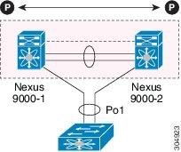
Figure 11. Peering Between vPC Devices for a Backup Routing Path


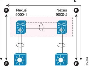
Peering Between Two Routers with vPC Devices as Transit Switches

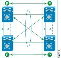
This example is similar to the Peering between Routers topology. The difference here is that the vPC domains are only used as Layer 2 transit paths. 

Figure 12. Peering Between Two Routers with vPC Devices as Transit Switches


Peering with an External Router on Parallel Interconnected Routed Ports

This example shows the Layer 3 device attached to the vPC domain through two different types of links, Layer 2 links and Layer 3 links. 

The Layer 2 links are used for bridged traffic (traffic staying in the same VLAN) or inter-VLAN traffic (assuming vPC domain hosts the interface VLAN and associated HSRP configuration). 

The Layer 3 links are used for routing protocol peering adjacency with each vPC peer device. 

The purpose of this topology is to attract specific traffic to go through the Layer 3 device. Layer 3 links are also used to carry routed traffic from a Layer 3 device to the vPC domain. 
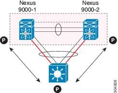
Figure 13. Peering with an External Router on Parallel Interconnected Routed Ports


Peering Over a vPC Interconnection on Parallel Interconnected Routed Ports

When routing protocol peering adjacency is required to be established between the two data centers, a best practice is to add dedicated Layer 3 links between the two sites as shown in this example. 

The vPC link between the two data centers carry bridged traffic or inter-VLAN traffic while the dedicated Layer 3 links carry the routed traffic across the two sites. 
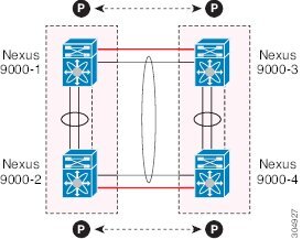
Figure 14. Peering Over a vPC Interconnection on Parallel Interconnected Routed Ports
Peering Over a PC Interconnection and Dedicated Interswitch Link Using non-vPC VLAN

This example shows when the Layer 3 device is single-attached to the vPC domain, you can use a non-vPC VLAN with a dedicated inter-switch link to establish the routing protocol peering adjacency between the Layer 3 device and each vPC peer device. However, the non-vPC VLAN must be configured to use a static MAC that is different than the vPC VLAN. 


Note


 Configuring the vPC VLAN (and vPC peer-link) for this purpose is not supported. 


Figure 15. Peering Over a PC Interconnection and Dedicated Interswitch Link Using non-vPC VLAN

CFSoE

The Cisco Fabric Services over Ethernet (CFSoE) is a reliable state transport mechanism that is used to synchronize the actions of the vPC peer devices. CFSoE carries messages and packets for many features linked with vPC, such as STP and IGMP. Information is carried in CFS/CFSoE protocol data units (PDUs).

When you enable the vPC feature, the device automatically enables CFSoE, and you do not have to configure anything. CFSoE distributions for vPCs do not need the capabilities to distribute over IP or the CFS regions. You do not need to configure anything for the CFSoE feature to work correctly on vPCs.

The CFSoE transport is local to each VDC.

You can use the show mac address-table command to display the MAC addresses that CFSoE synchronizes for the vPC peer link.


Note


Do not enter the no cfs eth distribute or the no cfs distribute command. You must enable CFSoE for vPC functionality. If you do enter either of these commands with vPC enabled, the system displays an error message.


When you enter the show cfs application command, the output displays “Physical-eth,” which shows the applications that are using CFSoE.


Note


The software does not support CFS regions.


vPC and Orphan Ports

When a device that is not vPC-capable connects to each peer, the connected ports are known as orphan ports because they are not members of a vPC. The device’s link to one peer will be active (forwarding) and the other link will be standby (blocking) due to STP.

If a peer link failure or restoration occurs, an orphan port’s connectivity might be bound to the vPC failure or restoration process. For example, if a device’s active orphan port connects to the secondary vPC peer, the device loses any connections through the primary peer if a peer link failure occurs and the vPC ports are suspended by the secondary peer. If the secondary peer were to also suspend the active orphan port, the device’s standby port becomes active, provides a connection to the primary peer, and restores connectivity. You can configure in the CLI that specific orphan ports are suspended by the secondary peer when it suspends its vPC ports and are restored when the vPC is restored.

vPC Recovery After an Outage

In a data center outage, both of the Cisco Nexus 3400-S devices that include a vPC get reloaded. Occasionally only one peer can be restored. With no functioning peer-keepalive or peer link, the vPC cannot function normally, but depending on your Cisco NX-OS release, a method might be available to allow vPC services to use only the local ports of the functional peer.

Autorecovery

You can configure the Cisco Nexus 3400-S device to restore vPC services when its peer fails to come online by using the auto-recovery command. You must save this setting in the startup configuration. On reload, if the peer link is down and three consecutive peer-keepalive messages are lost, the secondary device assumes the primary STP role and the primary LACP role. The software reinitializes the vPCs, bringing up its local ports. Because there are no peers, the consistency check is bypassed for the local vPC ports. The device elects itself to be the STP primary regardless of its role priority and also acts as the master device for LACP port roles.

vPC Peer Roles After a Recovery

When the other peer device completes its reload and adjacency forms, the following process occurs:

  1. The first vPC peer maintains its current role to avoid any transition reset to other protocols. The peer accepts the other available role.

  2. When an adjacency forms, consistency checks are performed and appropriate actions are taken.

High Availability

During an In-Service Software Upgrade (ISSU), the software reload process on the first vPC device locks its vPC peer device by using CFS messaging over the vPC communications channel. Only one device at a time is upgraded. When the first device completes its upgrade, it unlocks its peer device. The second device then performs the upgrade process, locking the first device as it does so. During the upgrade, the two vPC devices temporarily run different releases of Cisco NX-OS, however the system functions correctly because of its backward compatibility support.

vPC Forklift Upgrade Scenario

The following describes a scenario for migrating from a pair of Cisco Nexus 3400-S switches in a vPC topology to a different pair of Cisco Nexus 3400-S switches.

Considerations for a vPC forklift upgrade:

  • vPC Role Election and Sticky-bit

    When the two vPC systems are joined to form a vPC domain, priority decides which device is the vPC primary and which is the vPC secondary. When the primary device is reloaded, the system comes back online and connectivity to the vPC secondary device (now the operational primary) is restored. The operational role of the secondary device (operational primary) does not change (to avoid unnecessary disruptions). This behavior is achieved with a sticky-bit, where the sticky information is not saved in the startup configuration. This method makes the device that is up and running win over the reloaded device. Hence, the vPC primary becomes the vPC operational secondary. Sticky-bit is also set when a vPC node comes up with peer-link and peer-keepalive down and it becomes primary after the auto recovery period.

  • vPC Delay Restore

    The delay restore timer is used to delay the vPC from coming up on the restored vPC peer device after a reload when the peer adjacency is already established.

    To delay the VLAN interfaces on the restored vPC peer device from coming up, use the interfaces-vlan option of the delay restore command.

  • vPC Auto-Recovery

    During a data center power outage when both vPC peer switches go down, if only one switch is restored, the auto-recovery feature allows that switch to assume the role of the primary switch and the vPC links come up after the auto-recovery time period. The default auto-recovery period is 240 seconds.

The following example is a migration scenario that replaces vPC peer nodes Node1 and Node2 with New_Node1 and New_Node2.

Migration Step

Expected Behavior

Node1 Configured role ( Ex: role priority 100)

Node1 Operational role

Node2 Configured role (Ex: role priority 200)

Node2 Operational role

1

Initial state

Traffic is forwarded by both vPC peers – Node1 and Node2.

Node1 is primary and Node2 is secondary.

primary

Primary

Sticky bit: False

secondary

Secondary

Sticky bit: False

2

Node2 replacement – Shut all vPCs and uplinks on Node2. Peer-link and vPC peer-keepalive are in administrative up state.

Traffic converged on Primary vPC peer Node1.

primary

Primary

Sticky bit: False

secondary

Secondary

Sticky bit: False

3

Remove Node2.

Node1 will continue to forward traffic.

primary

Primary

Sticky bit: False

n/a

n/a

4

Configure New_Node2. Copy the configuration to startup config. vPC peer-link and peer-keepalive in administrative up state.

Power off New_Node2.

Make all connections.

Power on New_Node2.

New_Node2 will come up as secondary. Node1 continue to be primary.

Traffic will continue to be forwarded on Node01.

primary

Primary

Sticky bit: False

secondary

Secondary

Sticky bit: False

5

Bring up all vPCs and uplink ports on New_Node2.

Traffic will be forwarded by both Node 1 and New_Node2.

primary

Primary

Sticky bit: False

secondary

Secondary

Sticky bit: False

6

Node1 replacement -

Shut vPCs and uplinks on Node1.

Traffic will converge on New_Node2.

primary

Primary

Sticky bit: False

secondary

Secondary

Sticky bit: False

7

Remove Node1.

New_Node2 will become secondary, operational primary and sticky bit will be set to True.

n/a

n/a

secondary

Primary

Sticky bit: True

8

Configure New_Node1. Copy running to startup.

Power off the new Node1. Make all connections. Power on New_Node1.

New_Node1 will come up as primary, operational secondary.

primary

Secondary

Sticky bit: False

secondary

Primary

Sticky bit: True

9

Bring up all vPCs and uplink ports on New_Node1.

Traffic will be forwarded by both New Node1 and new Node2.

primary

Secondary

Sticky bit: False

secondary

Primary

Sticky bit: True


Note


If you prefer to have the configured secondary node as the operational secondary and the configured primary as the operational primary, then Node2 can be reloaded at the end of the migration. This is optional and does not have any functional impact.


Guidelines and Limitations

vPCs have the following configuration guidelines and limitations:

  • Make sure that both vPC peers are in the same mode (regular mode or enhanced mode) before performing a nondisruptive upgrade.

  • show commands with the internal keyword are not supported.

  • Cisco Nexus 3400-S switches do not support NAT on vPC topology.

  • The spanning-tree pseudo-information command is not available on Cisco Nexus 3400-S switches.

  • The delay restore interface-bridge-domain and peer-gateway exclude-bridge-domain commands are not available on Cisco Nexus 3400-S switches.

  • vPC peers must run the same Cisco NX-OS release. During a software upgrade, make sure to upgrade the primary vPC peer first.

  • All ports for a given vPC must be in the same VDC.

  • You must enable vPCs before you can configure them.

  • You must configure the peer-keepalive link and messages before the system can form the vPC peer link.

  • Only Layer 2 port channels can be in vPCs.

  • You must configure both vPC peer devices; the configuration is not sent from one device to the other.

  • To configure multilayer (back-to-back) vPCs, you must assign unique vPC domain ID for each respective vPC.

  • Check that the necessary configuration parameters are compatible on both sides of the vPC peer link. See the “Compatibility Parameters for vPC Interfaces” section for information about compatibility recommendations.

  • You may experience minimal traffic disruption while configuring vPCs.

  • The software does not support DHCP snooping, DAI, or IPSG in a vPC environment; DHCP Relay is supported.

  • The software does not support CFS regions.

  • Port security is not supported on port channels.

  • When peer-switch features are configured under vpc domain configuration mode on two Cisco Nexus 3400-S switches, the spanning-tree root changes even for VLANs that are not enabled on the vPC peer-link. Both the switches act as one system with one MAC address as the bridge address. This is true even for non-vPC mst-instance or VLANs. Therefore, a non vPC peer-link between the two switches gets blocked as a backup link. This is an expected behavior.

  • We recommend that you configure all the port channels in the vPC using LACP with the interfaces in active mode.

  • Back-to-back, multilayer vPC topologies require unique domain IDs on each respective vPC.

  • Having the same Hot Standby Router Protocol (HSRP)/Virtual Router Redundancy Protocol (VRRP) group on all nodes on a double sided vPC is supported..

  • When using vPCs, we recommend that you use default timers for FHRP (HSRP, VRRP) configurations. There is no advantage in convergence times when using aggressive timers in vPC configurations.

  • If you configure open shortest path first (OSPF) in a vPC environment, use the following timer commands in router configuration mode on the core switch to ensure fast OSPF convergence when a vPC peer link is shut down:

    
    switch (config-router)# timers throttle spf 1 50 50
    switch (config-router)# timers lsa-arrival 10


    See the Cisco Nexus 3400-S NX-OS Unicast Routing Configuration Guide for further details about OSPF.

  • The STP port cost is fixed to 200 in a vPC environment.

  • Jumbo frames are enabled by default on the vPC peer link.

  • To accommodate increased traffic when the vPC goes down and traffic needs to cross the peer-link, it is a best practice to use multiple high bandwidth interfaces (such as the 100G and/or 400G interfaces for the Cisco Nexus 3400-S) across linecards for the peer-link.

  • The vpc orphan-ports suspend command also applies to ports in non-vPC VLANs and Layer 3 ports. However, it is recommended to be used with ports in VPC VLANs.

  • A vPC port channel member link that is operating in Individual state will be flapped while checking for VLAN inconsistencies. To avoid having the link flapped during server provisioning, disable the VPC graceful consistency check with the no graceful consistency-check command.

    The following example disables the VPC graceful consistency check:

    
    switch# conf t
    Enter configuration commands, one per line. End with CNTL/Z.
    
    switch(config)# vpc domain 1
    switch(config-vpc-domain)# no graceful consistency-check  
    
  • vPC STP hitless role change feature is supported.

  • vPC role change can be performed from either of the peer devices.

  • If the original secondary device has higher role priority value than the original primary device, role swapping cannot be performed. Change the role priority on either vPC device so that the value of the original secondary device is lower than the original primary one. To view the existing role of a device, use the show vpc role command on local and peer switch.

  • Always check the existing configured role priority before configuring vPC hitless role change feature

  • In a vPC domain, enable the peer-switch command, where both vPC peers have same STP priorities, and ensure it is operational before issuing a role change. If you do not enable the peer-switch command, it can lead to convergence issues. Use show spanning-tree summary | grep peer command to verify whether the peer vPC switch is operational or not.

  • All the devices that are attached to a vPC domain must be dual homed.

Default Settings

The following table lists the default settings for vPC parameters.

Table 1. Default vPC Parameters

Parameters

Default

vPC system priority

32667

vPC peer-keepalive message

Disabled

vPC peer-keepalive interval

1 second

vPC peer-keepalive timeout

5 seconds

vPC peer-keepalive UDP port

3200

Configuring vPCs


Note


You must use these procedures on both devices on both sides of the vPC peer link. You configure both of the vPC peer devices using these procedures.


This section describes how to configure vPCs using the command-line interface (CLI).


Note


If you are familiar with the Cisco IOS CLI, be aware that the Cisco NX-OS commands for this feature might differ from the Cisco IOS commands that you would use.


Enabling vPCs

You must enable the vPC functionality before you can configure and use vPCs.

SUMMARY STEPS

  1. configure terminal
  2. feature vpc
  3. exit
  4. show feature
  5. copy running-config startup-config

DETAILED STEPS

  Command or Action Purpose

Step 1

configure terminal

Example:

switch# configure terminal
switch(config)#

Enters global configuration mode.

Step 2

feature vpc

Example:

switch(config)# feature vpc

Enables vPCs on the device.

Step 3

exit

Example:

switch(config)# exit
switch#

Exits global configuration mode.

Step 4

show feature

Example:

switch# show feature

(Optional) Displays which features are enabled on the device.

Step 5

copy running-config startup-config

Example:

switch# copy running-config startup-config

(Optional) Copies the running configuration to the startup configuration.

Example

This example shows how to enable the vPC feature:

switch# configure terminal
switch(config)# feature vpc
switch(config)# exit
switch(config)#

Disabling vPCs


Note


When you disable the vPC functionality, the device clears all the vPC configurations.


SUMMARY STEPS

  1. configure terminal
  2. no feature vpc
  3. exit
  4. show feature
  5. copy running-config startup-config

DETAILED STEPS

  Command or Action Purpose

Step 1

configure terminal

Example:

switch# configure terminal
switch(config)#

Enters global configuration mode.

Step 2

no feature vpc

Example:

switch(config)# no feature vpc

Disables vPCs on the device.

Step 3

exit

Example:

switch(config)# exit
switch#

Exits global configuration mode.

Step 4

show feature

Example:

switch# show feature

(Optional) Displays which features are enabled on the device.

Step 5

copy running-config startup-config

Example:

switch# copy running-config startup-config

(Optional) Copies the running configuration to the startup configuration.

Example

This example shows how to disable the vPC feature:

switch# configure terminal
switch(config)# no feature vpc
switch(config)# exit
switch#

Creating a vPC Domain and Entering vpc-domain Mode

You can create a vPC domain and put the vPC peer link port channels into the identical vPC domain on both vPC peer devices. Use a unique vPC domain number throughout a single vPC domain . This domain ID is used to automatically to form the vPC system MAC address.

You can also use this command to enter vpc-domain command mode.

SUMMARY STEPS

  1. configure terminal
  2. vpc domain domain-id [shut | no shut]
  3. exit
  4. show vpc brief
  5. copy running-config startup-config

DETAILED STEPS

  Command or Action Purpose

Step 1

configure terminal

Example:

switch# configure terminal
switch(config)#

Enters global configuration mode.

Step 2

vpc domain domain-id [shut | no shut]

Example:

switch(config)# vpc domain 5
switch(config-vpc-domain)#

Creates a vPC domain on the device, and enters vpc-domain configuration mode for configuration purposes. There is no default; the range is from 1 to 1000.

Step 3

exit

Example:

switch(config)# exit
switch#

Exits vpc-domain configuration mode.

Step 4

show vpc brief

Example:

switch# show vpc brief

(Optional) Displays brief information about each vPC domain.

Step 5

copy running-config startup-config

Example:

switch# copy running-config startup-config

(Optional) Copies the running configuration to the startup configuration.

Example

This example shows how to enter the vpc-domain command mode to configure an existing vPC domain:


switch# configure terminal
switch(config)# vpc domain 5
switch(config-vpc-domain)# exit
switch(config)#

Configuring a vPC Keepalive Link and Messages


Note


You must configure the vPC peer-keepalive link before the system can form the vPC peer link.


You can configure the destination IP for the peer-keepalive link that carries the keepalive messages. Optionally, you can configure other parameters for the keepalive messages.


Note


We recommend that you configure a separate VRF instance and put a Layer 3 port from each vPC peer device into that VRF for the vPC peer-keepalive link. Do not use the peer link itself to send vPC peer-keepalive messages. For information about creating and configuring VRFs, see the Cisco Nexus 3400-S NX-OS Unicast Routing Configuration Guide . Ensure that both the source and destination IP addresses use for the peer-keepalive message are unique in your network. The management port and management VRF are the defaults for these keepalive messages.


Before you begin

Ensure that you have enabled the vPC feature.

SUMMARY STEPS

  1. configure terminal
  2. vpc domain domain-id [shut | no shut]
  3. peer-keepalive destination ipaddress [hold-timeout secs | interval msecs {timeout secs} | {precedence {prec-value | network | internet | critical | flash-override | flash | immediate priority | routine}} | tos {tos-value | max-reliability | max-throughput | min-delay | min-monetary-cost | normal}} |tos-byte tos-byte-value} | source ipaddress | vrf {name | management vpc-keepalive}]
  4. exit
  5. show vpc statistics
  6. copy running-config startup-config

DETAILED STEPS

  Command or Action Purpose

Step 1

configure terminal

Example:

switch# configure terminal
switch(config)#

Enters global configuration mode.

Step 2

vpc domain domain-id [shut | no shut]

Example:

switch(config)# vpc domain 5
switch(config-vpc-domain)#

Creates a vPC domain on the device, and enters vpc-domain configuration mode.

Step 3

peer-keepalive destination ipaddress [hold-timeout secs | interval msecs {timeout secs} | {precedence {prec-value | network | internet | critical | flash-override | flash | immediate priority | routine}} | tos {tos-value | max-reliability | max-throughput | min-delay | min-monetary-cost | normal}} |tos-byte tos-byte-value} | source ipaddress | vrf {name | management vpc-keepalive}]

Example:

switch(config-vpc-domain)# peer-keepalive destination 172.28.230.85
switch(config-vpc-domain)#

Configures the IPv4 address for the remote end of the vPC peer-keepalive link.

Note


The system does not form the vPC peer link until you configure a vPC peer-keepalive link.

The management ports and VRF are the defaults.

Note


We recommend that you configure a separate VRF and use a Layer 3 port from each vPC peer device in that VRF for the vPC peer-keepalive link..

Step 4

exit

Example:

switch(config)# exit
switch#

Exits global configuration mode.

Step 5

show vpc statistics

Example:

switch# show vpc statistics

(Optional) Displays information about the configuration for the keepalive messages.

Step 6

copy running-config startup-config

Example:

switch# copy running-config startup-config

(Optional) Copies the running configuration to the startup configuration.

Example

This example shows how to configure the destination and source IP address and VRF for the vPC-peer-keepalive link:

switch# configure terminal
switch(config)# vpc domain 100
switch(config-vpc-domain)# peer-keepalive destination 172.168.1.2 source 172.168.1.1 vrf
vpc-keepalive
switch(config-vpc-domain)# exit
switch#

Creating a vPC Peer Link

You create the vPC peer link by designating the port channel that you want on each device as the peer link for the specified vPC domain. We recommend that you configure the Layer 2 port channels that you are designating as the vPC peer link in trunk mode and that you use two ports on separate modules on each vPC peer device for redundancy.

Before you begin

Ensure that you have enabled the vPC feature.

SUMMARY STEPS

  1. configure terminal
  2. interface port-channel channel-number
  3. switchport mode trunk
  4. switchport trunk allowed vlan vlan-list
  5. vpc peer-link
  6. exit
  7. show vpc brief
  8. copy running-config startup-config

DETAILED STEPS

  Command or Action Purpose

Step 1

configure terminal

Example:

switch# configure terminal
switch(config)#

Enters global configuration mode.

Step 2

interface port-channel channel-number

Example:

switch(config)# interface port-channel 20
switch(config-if)#

Selects the port channel that you want to use as the vPC peer link for this device, and enters interface configuration mode.

Step 3

switchport mode trunk

Example:

switch(config-if)# switchport mode trunk

(Optional) Configures this interface in trunk mode.

Step 4

switchport trunk allowed vlan vlan-list

Example:

switch(config-if)# switchport trunk
allowed vlan 1-120,201-3967

(Optional) Configures the permitted VLAN list.

Step 5

vpc peer-link

Example:

switch(config-if)# vpc peer-link
switch(config-vpc-domain)#

Configures the selected port channel as the vPC peer link, and enters vpc-domain configuration mode.

Step 6

exit

Example:

switch(config)# exit
switch#

Exits vpc-domain configuration mode.

Step 7

show vpc brief

Example:

switch# show vpc brief

(Optional) Displays information about each vPC, including information about the vPC peer link.

Step 8

copy running-config startup-config

Example:

switch# copy running-config startup-config

(Optional) Copies the running configuration to the startup configuration.

Example

This example shows how to configure a vPC peer link:

switch# configure terminal
switch(config)# interface port-channel 20
switch(config-if)# switchport mode
switch(config-if)# switchport mode trunk
switch(config-if)# switchport trunk allowed vlan 1-120,201-3967
switch(config-if)# vpc peer-link
switch(config-vpc-domain)# exit
switch(config)#

Configuring a vPC Peer-Gateway

You can configure vPC peer devices to act as the gateway for packets that are destined to the vPC peer device's MAC address.

Before you begin

Ensure that you have enabled the vPC feature.

SUMMARY STEPS

  1. configure terminal
  2. vpc domain domain-id [shut | no shut]
  3. peer-gateway
  4. exit
  5. show vpc brief
  6. copy running-config startup-config

DETAILED STEPS

  Command or Action Purpose

Step 1

configure terminal

Example:

switch# configure terminal
switch(config)#

Enters global configuration mode.

Step 2

vpc domain domain-id [shut | no shut]

Example:

switch(config-if)# vpc domain 5
switch(config-vpc-domain)#

Creates a vPC domain if it does not already exist, and enters vpc-domain configuration mode.

Step 3

peer-gateway

Example:

switch(config-vpc-domain)# peer-gateway

Note


Disable IP redirects on all interface-vlans of this vPC domain for correct operation of this feature.

Enables Layer 3 forwarding for packets destined to the peer's gateway MAC address.

Step 4

exit

Example:

switch(config)# exit
switch#

Exits vpc-domain configuration mode.

Step 5

show vpc brief

Example:

switch# show vpc brief

(Optional) Displays information about each vPC, including information about the vPC peer link.

Step 6

copy running-config startup-config

Example:

switch# copy running-config startup-config

(Optional) Copies the running configuration to the startup configuration.

Configuring Fast Convergence

Fast convergence feature is supported on Cisco Nexus 3400-S switches. You can enable or disable the vPC optimizations using this command. To achieve faster convergence, you must enable [no] fast-convergence on both vPC peers to achieve fast-convergence.

SUMMARY STEPS

  1. configure terminal
  2. switch(config) # vpc domain <domain>
  3. switch(config) # peer-switch
  4. switch(config) # show vpc peer-keepalive
  5. switch(config) # delay restore { time }
  6. switch(config) # peer-gateway
  7. switch(config) # delay restore orphan-port
  8. switch(config-vpc-domain)# fast-convergence

DETAILED STEPS

  Command or Action Purpose

Step 1

configure terminal

Enters global configuration mode.

Step 2

switch(config) # vpc domain <domain>

Configure the VPC domain number.

Step 3

switch(config) # peer-switch

Define the peer switch.

Step 4

switch(config) # show vpc peer-keepalive

Displays information about the peer keepalive messages

Step 5

switch(config) # delay restore { time }

Number of seconds to delay bringing up the restored vPC peer device. The range is from 1 to 3600.

Step 6

switch(config) # peer-gateway

To enable Layer 3 forwarding for packets destined to the gateway MAC address of the virtual Port Channel (vPC), use the peer-gateway command. To disable Layer 3 forwarding packets, use the no form of this command.

.

Step 7

switch(config) # delay restore orphan-port

Number of seconds to delay bringing up the restored device's orphan port

Step 8

switch(config-vpc-domain)# fast-convergence

Configure vPC fast convergence.

Configuring LACP vPC Convergence

Link Aggregation Control Protocol (LACP) vPC convergence feature is supported on Cisco Nexus 3400-S switches. You can configure LACP vPC convergence feature for more efficient use of port channels by reducing convergence time of vPC port channel for member link going down and first member bring up.

When you configure LACP vPC convergence on a Cisco Nexus 3400-S switch, it waits until all the VLANs are initialized and programmed and then send LACP sync PDU, which will start sending traffic to the VPC domain without drops. You may configure the lacp vpc-convergence command in a VXLAN and non-VXLAN environments that have vPC port-channels to hosts that support LACP.

SUMMARY STEPS

  1. configure terminal
  2. switch(config) # interface {type/slot | portchannel number}
  3. switch(config-if) # lacp vpc-convergence

DETAILED STEPS

  Command or Action Purpose

Step 1

configure terminal

Enters global configuration mode.

Step 2

switch(config) # interface {type/slot | portchannel number}

Specifies an interface to configure, and enters interface configuration mode.

Step 3

switch(config-if) # lacp vpc-convergence

Configure LACP convergence. Reduce the convergence time of the vPC port channel for member link going down and first member bring up.

Note


You must enable this command on both the vPC peer switches. This command must be configured only on PortFast ports (vPC port channels on which the spanning-tree port type edge [trunk] is enabled).

Note


In a vPC environment, when this command is not configured on vPC port-channel interfaces to devices that support LACP, and if one of the vPC peers is reloaded or if one of the links is brought up, the link(s) connected to the vPC peer switch in the 'up' state will remain active and forward traffic. The other link(s) may go down and will transition to the 'up' state. The links transitioning to the 'up' state starts initializing VLANs. When the VLANs are initialized, LACP sync PDUs are sent per initialized VLAN, which will bring port-channel into 'up' state and that leads to traffic black-hole for non-idealized VLANs.

Configuring Layer 3 over vPC

Before you begin

Ensure that the peer-gateway feature is enabled and it is configured on both the peers and both the peers run an image that supports Layer 3 over vPC. If you enter the layer3 peer-router command without enabling the peer-gateway feature, a syslog message is displayed recommending you to enable the peer-gateway feature.

Ensure that the peer link is up.

SUMMARY STEPS

  1. switch# configure terminal
  2. switch(config)# vpc domain domain-id
  3. switch(config-vpc-domain)#layer3 peer-router
  4. switch(config-vpc-domain)# exit
  5. (Optional) switch#show vpc brief
  6. (Optional) switch#copy running-config startup-config

DETAILED STEPS

  Command or Action Purpose

Step 1

switch# configure terminal

Example:

switch# configure terminal
switch(config)#

Enters global configuration mode.

Step 2

switch(config)# vpc domain domain-id

Example:

switch(config)# vpc domain 5
switch(config-vpc-domain)#

Creates a vPC domain if it does not already exist, and enters the vpc-domain configuration mode. There is no default; the range is from <1 to 1000>.

Step 3

switch(config-vpc-domain)#layer3 peer-router

Enables the Layer 3 device to form peering adjacency with both the peers.

Note


Configure this command in both the peers. If you configure this command only on one of the peers or you disable it on one peer, the operational state of layer 3 peer-router gets disabled. You get a notification when there is a change in the operational state.

Step 4

switch(config-vpc-domain)# exit

Exits the vpc-domain configuration mode.

Step 5

(Optional) switch#show vpc brief

(Optional)

Displays brief information about each vPC domain.

Step 6

(Optional) switch#copy running-config startup-config

(Optional)

Copies the running configuration to the startup configuration.

Example

The following example shows how to configure Layer 3 over vPC feature:

switch# configure terminal
switch(config)# vpc domain 5
switch(config-vpc-domain)# layer3 peer-router

switch(config-vpc-domain)# exit

switch(config)#

This example shows how to verify if the Layer 3 over vPC feature is configured. The Operational Layer3 Peer is enabled or disabled depending up on how the operational state of Layer 3 over vPC is configured.

switch# show vpc brief

vPC domain id : 5
Peer status : peer adjacency formed ok
vPC keep-alive status : peer is alive
Configuration consistency status : success
Per-vlan consistency status : failed
Type-2 consistency status : success
vPC role : secondary
Number of vPCs configured : 2
Peer Gateway : Enabled
Peer gateway excluded VLANs : -
Dual-active excluded VLANs : -
Graceful Consistency Check : Enabled
Auto-recovery status : Enabled (timeout = 240 seconds)
Operational Layer3 Peer : Enabled

Layer 3 over vPC Supported Topologies

See the following Layer 3 over vPC supported topologies:

Figure 16.  Supported: Peering Over a vPC Interconnection Where the Router Peers with Both the vPC Peers. 
Figure 17. Supported: Peering Over an STP Interconnection Using a vPC VLAN Where the Router Peers with Both the vPC Peers.
Figure 18. Supported: Peering Over an Orphan Device with Both the vPC Peers.


Figure 19. Supported: Peering Over a vPC Interconnection Where Each Nexus Device Peers with Two vPC Peers. 


Configuring a Graceful Consistency Check

You can configure the graceful consistency check feature, which is enabled by default. Unless this feature is enabled, the vPC is completely suspended when a mismatch in a mandatory compatibility parameter is introduced in a working vPC. When this feature is enabled, only the links on the secondary peer device are suspended. See the “Compatibility Parameters for vPC Interfaces” section for information about consistent configurations on the vPCs.

SUMMARY STEPS

  1. configure terminal
  2. vpc domain domain-id [shut | no shut]
  3. graceful consistency-check
  4. exit
  5. show vpc brief

DETAILED STEPS

  Command or Action Purpose

Step 1

configure terminal

Example:

switch# configure terminal
switch(config)#

Enters global configuration mode.

Step 2

vpc domain domain-id [shut | no shut]

Example:

switch(config-if)# vpc domain 5
switch(config-vpc-domain)#

Creates a vPC domain if it does not already exist, and enters vpc-domain configuration mode.

Step 3

graceful consistency-check

Example:

switch(config-vpc-domain)# graceful consistency-check

Specifies that only the links on the secondary peer device are suspended when a mismatch is detected in a mandatory compatibility parameter.

Use the no form of this command to disable the feature.

Step 4

exit

Example:

switch(config)# exit
switch#

Exits vpc-domain configuration mode.

Step 5

show vpc brief

Example:

switch# show vpc brief

(Optional) Displays information on the vPCs.

Example

This example shows how to enable the graceful consistency check feature:

switch# configure terminal
switch(config)# vpc domain 5
switch(config-vpc-domain)# graceful consistency-check
switch(config-vpc-domain)# exit
switch(config)#

Checking the Configuration Compatibility on a vPC Peer Link

After you have configured the vPC peer link on both vPC peer devices, check that the configurations are consistent on all vPC interfaces. See the “Compatibility Parameters for vPC Interfaces” section for information about consistent configurations on the vPCs.

SUMMARY STEPS

  1. configure terminal
  2. show vpc consistency-parameters {global | interface port-channel channel-number}

DETAILED STEPS

  Command or Action Purpose

Step 1

configure terminal

Example:

switch# configure terminal
switch(config)#

Enters global configuration mode.

Step 2

show vpc consistency-parameters {global | interface port-channel channel-number}

Example:

switch(config)# show vpc consistency-parameters global
switch(config)#

(Optional) Displays the status of those parameters that must be consistent across all vPC interfaces.

Example

This example shows how to check that the required configurations are compatible across all the vPC interfaces:

switch# configure terminal
switch(config)# show vpc consistency-parameters global
switch(config)#

Note


Messages regarding the vPC interface configuration compatibility are also logged to the syslog.


Moving Other Port Channels into a vPC

We recommend that you attach the vPC domain downstream port channel to two devices for redundancy.

To connect to the downstream device, you create a port channel from the downstream device to the primary vPC peer device and you create another port channel from the downstream device to the secondary peer device. On each vPC peer device, you assign a vPC number to the port channel that connects to the downstream device. You will experience minimal traffic disruption when you are creating vPCs.

Before you begin

Ensure that you have enabled the vPC feature.

Ensure that you are using a Layer 2 port channel.

SUMMARY STEPS

  1. configure terminal
  2. interface port-channel channel-number
  3. vpc number
  4. exit
  5. show vpc brief
  6. copy running-config startup-config

DETAILED STEPS

  Command or Action Purpose

Step 1

configure terminal

Example:

switch# configure terminal
switch(config)#

Enters global configuration mode.

Step 2

interface port-channel channel-number

Example:

switch(config)# interface port-channel 20
switch(config-if)#

Selects the port channel that you want to put into the vPC to connect to the downstream device, and enters interface configuration mode.

Step 3

vpc number

Example:

switch(config-if)# vpc 5
switch(config-vpc-domain)#

Configures the selected port channel into the vPC to connect to the downstream device. You can use any module in the device for these port channels. The range is from 1 and 4096.

Note


The vPC number that you assign to the port channel connecting to the downstream device from the vPC peer device must be identical on both vPC peer devices.

Step 4

exit

Example:

switch(config)# exit
switch#

Exits vpc-domain configuration mode.

Step 5

show vpc brief

Example:

switch# show vpc brief

(Optional) Displays information on the vPCs.

Step 6

copy running-config startup-config

Example:

switch# copy running-config startup-config

(Optional) Copies the running configuration to the startup configuration.

Example

This example shows how to configure a port channel to connect to the downstream device:

switch# configure terminal
switch(config)# interface port-channel 20
switch(config-if)# vpc 5
switch(config-if)# exit
switch(config)#

Manually Configuring a vPC Domain MAC Address

When you create a vPC domain, the Cisco NX-OS software automatically creates a vPC system MAC address, which is used for operations that are confined to the link-scope, such as LACP. However, you might choose to configure the vPC domain MAC address manually.

Before you begin

Ensure that you have enabled the vPC feature.

SUMMARY STEPS

  1. configure terminal
  2. vpc domain domain-id [shut | no shut]
  3. system-mac mac-address
  4. exit
  5. show vpc role
  6. copy running-config startup-config

DETAILED STEPS

  Command or Action Purpose

Step 1

configure terminal

Example:

switch# configure terminal
switch(config)#

Enters global configuration mode.

Step 2

vpc domain domain-id [shut | no shut]

Example:

switch(config)# vpc domain 5
switch(config-vpc-domain)#

Enters the vPC domain number that you want to configure. The system enters vpc-domain configuration mode.

Step 3

system-mac mac-address

Example:

switch(config-vpc-domain)# system-mac 23fb.4ab5.4c4e
switch(config-vpc-domain)#

Enters the MAC address that you want for the specified vPC domain in the following format: aaaa.bbbb.cccc.

Step 4

exit

Example:

switch(config-vpc-domain)# exit
switch#

Exits vpc-domain configuration mode.

Step 5

show vpc role

Example:

switch# show vpc brief

(Optional) Displays the vPC system MAC address.

Step 6

copy running-config startup-config

Example:

switch# copy running-config startup-config

(Optional) Copies the running configuration to the startup configuration.

Example

This example shows how to manually configure a vPC domain MAC address:

switch# configure terminal
switch(config)# vpc domain 5
switch(config-vpc-domain)# system-mac 13gb.4ab5.4c4e
switch(config-vpc-domain)# exit
switch(config)#

Manually Configuring the System Priority

When you create a vPC domain, the system automatically creates a vPC system priority. However, you can also manually configure a system priority for the vPC domain.


Note


We recommend that you manually configure the vPC system priority when you are running LACP to ensure that the vPC peer devices are the primary devices on LACP. When you manually configure the system priority, ensure that you configure the same priority value on both vPC peer devices. If these values do not match, vPC does not come up.


Before you begin

Ensure that you have enabled the vPC feature.

SUMMARY STEPS

  1. configure terminal
  2. vpc domain domain-id [shut | no shut]
  3. system-priority priority
  4. exit
  5. show vpc role
  6. copy running-config startup-config

DETAILED STEPS

  Command or Action Purpose

Step 1

configure terminal

Example:

switch# configure terminal
switch(config)#

Enters global configuration mode.

Step 2

vpc domain domain-id [shut | no shut]

Example:

switch(config)# vpc domain 5
switch(config-vpc-domain)#

Enters the vPC domain number that you want to configure. The system enters vpc-domain configuration mode.

Step 3

system-priority priority

Example:

switch(config-vpc-domain)# system-priority 4000
switch(config-vpc-domain)#

Enters the system priority that you want for the specified vPC domain. The range of values is from 1 to 65535. The default value is 32667.

Step 4

exit

Example:

switch(config-vpc-domain)# exit
switch#

Exits vpc-domain configuration mode.

Step 5

show vpc role

Example:

switch# show vpc role

(Optional) Displays the vPC system priority.

Step 6

copy running-config startup-config

Example:

switch# copy running-config startup-config

(Optional) Copies the running configuration to the startup configuration.

Example

This example shows how to manually configure the vPC domain system priority:

switch# configure terminal
switch(config)# vpc domain 5
switch(config-vpc-domain)# system-priority 4000
switch(config-vpc-domain)# exit
switch(config)#

Manually Configuring the vPC Peer Device Role

By default, the Cisco NX-OS software elects a primary and secondary vPC peer device after you configure the vPC domain and both sides of the vPC peer link. However, you might want to elect a specific vPC peer device as the primary device for the vPC. Then, you would manually configure the role value for the vPC peer device that you want as the primary device to be lower than the other vPC peer device.

vPCs do not support role preemption. If the primary vPC peer device fails, the secondary vPC peer device takes over to become operationally the vPC primary device. However, the original operational roles are not restored if the formerly primary vPC comes up again.

Before you begin

Ensure that you have enabled the vPC feature.

SUMMARY STEPS

  1. configure terminal
  2. vpc domain domain-id [shut | no shut]
  3. role priority priority
  4. exit
  5. show vpc role
  6. copy running-config startup-config

DETAILED STEPS

  Command or Action Purpose

Step 1

configure terminal

Example:

switch# configure terminal
switch(config)#

Enters global configuration mode.

Step 2

vpc domain domain-id [shut | no shut]

Example:

switch(config)# vpc domain 5
switch(config-vpc-domain)#

Enters the vPC domain number that you want to configure. The system enters vpc-domain configuration mode.

Step 3

role priority priority

Example:

switch(config-vpc-domain)# role priority 4
switch(config-vpc-domain)#

Enters the role priority that you want for the vPC system priority. The range of values is from 1 to 65636, and the default value is 32667. A lower value means that this switch has a better chance of being the primary vPC.

Step 4

exit

Example:

switch(config)# exit
switch#

Exits vpc-domain configuration mode.

Step 5

show vpc role

Example:

switch# show vpc role

(Optional) Displays the vPC system priority.

Step 6

copy running-config startup-config

Example:

switch# copy running-config startup-config

(Optional) Copies the running configuration to the startup configuration.

Example

This example shows how to manually configure the role priority of the vPC peer device:

switch# configure terminal
switch(config)# vpc domain 5
switch(config-vpc-domain)# role priority 4
switch(config-vpc-domain)# exit
switch(config)#

Configuring the Tracking Feature on a Single-Module vPC

If you must configure all the vPC peer links and core-facing interfaces on a single module, you should configure a track object and a track list that is associated with the Layer 3 link to the core and on all the links on the vPC peer link on both primary vPC peer devices. Once you configure this feature and if the primary vPC peer device fails, the system automatically suspends all the vPC links on the primary vPC peer device. This action forces all the vPC traffic to the secondary vPC peer device until the system stabilizes.

You must put this configuration on both vPC peer devices. Additionally, you should put the identical configuration on both vPC peer devices because either device can become the operationally primary vPC peer device.

Before you begin

Ensure that you have enabled the vPC feature.

Ensure that you have configured the track object and the track list. Ensue that you assign all interfaces that connect to the core and to the vPC peer link to the track-list object on both vPC peer devices.

SUMMARY STEPS

  1. configure terminal
  2. vpc domain domain-id [shut | no shut]
  3. track track-object-id
  4. exit
  5. show vpc brief
  6. copy running-config startup-config

DETAILED STEPS

  Command or Action Purpose

Step 1

configure terminal

Example:

switch# configure terminal
switch(config)#

Enters global configuration mode.

Step 2

vpc domain domain-id [shut | no shut]

Example:

switch(config)# vpc domain 5
switch(config-vpc-domain)#

Enters the vPC domain number that you want to configure, and enters vpc-domain configuration mode.

Step 3

track track-object-id

Example:

switch(config-vpc-domain)# track object 23
switch(config-vpc-domain)#

Adds the previously configured track-list object with its associated interfaces to the vPC domain.

Step 4

exit

Example:

switch(config-vpc-domain)# exit
switch#

Exits vpc-domain configuration mode.

Step 5

show vpc brief

Example:

switch# show vpc brief

(Optional) Displays information about the tracked objects.

Step 6

copy running-config startup-config

Example:

switch# copy running-config startup-config

(Optional) Copies the running configuration to the startup configuration.

Example

This example shows how to put the previously configured track-list object into the vPC domain on the vPC peer device:

switch# configure terminal
switch(config)# vpc domain 5
switch(config-vpc-domain)# track object 5
switch(config-vpc-domain)# exit
switch(config)#

Configuring for Recovery After an Outage

If an outage occurs, the vPC waits for a peer adjacency to form on a switch reload. This situation can result in an unacceptably long service disruption. You can configure the Cisco Nexus 3400-S device to restore vPC services when its peer fails to come on line.

Configuring Reload Restore

The reload restore command and procedure described in this section is deprecated. We recommend that you use the auto-recovery command and procedure described in the “Configuring an Autorecovery” section.

You can configure the Cisco Nexus 3400-S device to restore vPC services when its peer fails to come online by using the reload restore command.

Before you begin

Ensure that you have enabled the vPC feature.

SUMMARY STEPS

  1. configure terminal
  2. vpc domain domain-id [shut | no shut]
  3. reload restore [delay time-out]
  4. exit
  5. show running-config vpc
  6. show vpc consistency-parameters interface port-channel number
  7. copy running-config startup-config

DETAILED STEPS

  Command or Action Purpose

Step 1

configure terminal

Example:
switch# configure terminal
switch(config)#

Enters global configuration mode.

Step 2

vpc domain domain-id [shut | no shut]

Example:
switch(config)# vpc domain 5
switch(config-vpc-domain)#

Enters the vPC domain number that you want to configure, and enters vpc-domain configuration mode.

Step 3

reload restore [delay time-out]

Example:
switch(config-vpc-domain)# reload restore

Configures the vPC to assume its peer is not functional and to bring up the vPC. The default delay is 240 seconds. You can configure a time-out delay from 240 to 3600 seconds.

Use the no form of the command to reset the vPC to its default settings.

Step 4

exit

Example:
switch(config-vpc-domain)# exit
switch#

Exits vpc-domain configuration mode.

Step 5

show running-config vpc

Example:
switch# show running-config vpc

(Optional) Displays information about the vPC, specifically the reload status.

Step 6

show vpc consistency-parameters interface port-channel number

Example:
switch# show vpc consistency-parameters
interface port-channel 1

(Optional) Displays information about the vPC consistency parameters for the specified interface.

Step 7

copy running-config startup-config

Example:
switch# copy running-config startup-config

(Optional) Copies the running configuration to the startup configuration.

Note


To ensure the reload feature is enabled, you should perform this step.

Example

This example shows how to set the vPC reload restore feature and save it in the switch startup configuration:

switch# configure terminal
Enter configuration commands, one per line. End with CNTL/Z.
switch(config)# vpc domain 5
switch(config-vpc-domain)# reload restore

Warning:
Enables restoring of vPCs in a peer-detached state after reload, will wait for 240
seconds (by default) to determine if peer is un-reachable

switch(config-vpc-domain)# exit
switch(config)# exit
switch# copy running-config startup-config
switch# show running-config vpc

!Command: show running-config vpc
!Time: Wed Mar 24 18:43:54 2010
version 5.0(2)
feature vpc
logging level vpc 6
vpc domain 5
reload restore

This example shows how to examine the consistency parameters:

switch# show vpc consistency-parameters interface port-channel 1

Legend:
Type 1 : vPC will be suspended in case of mismatch
Name Type Local Value Peer Value
------------- ---- ----------- ---------------
STP Port Type 1 Default -
STP Port Guard 1 None -
STP MST Simulate PVST 1 Default -
mode 1 on -
Speed 1 1000 Mb/s -
Duplex 1 full -
Port Mode 1 trunk -
Native Vlan 1 1 -
MTU 1 1500 -
Allowed VLANs - 1-3967,4048-4093
Local suspended VLANs

Configuring an Autorecovery

You can configure the Cisco Nexus 3400 device to restore vPC services when its peer fails to come online by using the auto-recovery command.


Note


The auto-recovery feature is not enabled by default on Cisco Nexus 3400 switches. When the object tracking is triggered, the vPC secondary peer device does not change its role to that primary device and it reinitializes the vPC legs. You must manually configure auto-recovery on the vPC secondary peer device so that it can take over the primary role and reinitialize its vPC legs.


Before you begin

Ensure that you have enabled the vPC feature.

SUMMARY STEPS

  1. configure terminal
  2. vpc domain domain-id [shut | no shut]
  3. auto-recovery [reload-delay time]
  4. exit
  5. show running-config vpc
  6. show vpc consistency-parameters interface port-channel number
  7. copy running-config startup-config

DETAILED STEPS

  Command or Action Purpose

Step 1

configure terminal

Example:
switch# configure terminal
switch(config)#

Enters global configuration mode.

Step 2

vpc domain domain-id [shut | no shut]

Example:
switch(config)# vpc domain 5
switch(config-vpc-domain)#

Enters the vPC domain number that you want to configure, and enters vpc-domain configuration mode.

Step 3

auto-recovery [reload-delay time]

Example:
switch(config-vpc-domain)# auto-recovery

Configures the vPC to assume its peer is not functional and to bring up the vPC, and specifies the time to wait after a reload to restore the vPC. The default delay is 240 seconds. You can configure a delay from 240 to 3600 seconds.

Use the no form of the command to reset the vPC to its default settings.

Step 4

exit

Example:
switch(config-vpc-domain)# exit
switch#

Exits vpc-domain configuration mode.

Step 5

show running-config vpc

Example:
switch# show running-config vpc

(Optional) Displays information about the vPC, specifically the reload status.

Step 6

show vpc consistency-parameters interface port-channel number

Example:
switch# show vpc consistency-parameters
interface port-channel 1

(Optional) Displays information about the vPC consistency parameters for the specified interface.

Step 7

copy running-config startup-config

Example:
switch# copy running-config startup-config

(Optional) Copies the running configuration to the startup configuration.

Note


To ensure the autorecovery feature is enabled, you should perform this step.

Example

This example shows how to set the vPC autorecovery feature and save it in the switch startup configuration:

switch# configure terminal
Enter configuration commands, one per line. End with CNTL/Z.
switch(config)# vpc domain 5
switch(config-vpc-domain)# auto-recovery

Warning:
Enables restoring of vPCs in a peer-detached state after reload, will wait for 240
seconds to determine if peer is un-reachable

switch(config-vpc-domain)# exit
switch(config)# exit
switch# copy running-config startup-config

Configuring the Suspension of Orphan Ports

When a device that is not vPC-capable connects to each peer, the connected ports are known as orphan ports because they are not members of a vPC. You can explicitly declare physical interfaces as orphan ports to be suspended (shut down) by the secondary peer when it suspends its vPC ports in response to a peer link or peer-keepalive failure. The orphan ports are restored when the vPC is restored.


Note


You can configure vPC orphan port suspension only on physical ports, portchannels. However, you cannot configure the same on individual port channel member ports.


Before you begin

Ensure that you have enabled the vPC feature.

SUMMARY STEPS

  1. configure terminal
  2. show vpc orphan-ports
  3. interface type slot/port
  4. vpc orphan-port suspend
  5. exit
  6. copy running-config startup-config

DETAILED STEPS

  Command or Action Purpose

Step 1

configure terminal

Example:

switch# configure terminal
switch(config)#

Enters global configuration mode.

Step 2

show vpc orphan-ports

Example:

switch# show vpc orphan-ports

(Optional) Displays a list of the orphan ports.

Step 3

interface type slot/port

Example:

switch(config)# interface ethernet 3/1
switch(config-if)#

Specifies an interface to configure, and enters interface configuration mode.

Step 4

vpc orphan-port suspend

Example:

switch(config-if)# vpc orphan-ports suspend

Configures the selected interface as a vPC orphan port to be suspended by the secondary peer in the case of a vPC failure.

Step 5

exit

Example:

switch(config-if)# exit
switch#

Exits interface configuration mode.

Step 6

copy running-config startup-config

Example:

switch# copy running-config startup-config

(Optional) Copies the running configuration to the startup configuration.

Example

This example shows how to configure an interface as a vPC orphan port to be suspended by the secondary peer in the case of a vPC failure:

switch# configure terminal
switch(config)# interface ethernet 3/1
switch(config-if)# vpc orphan-ports suspend
switch(config-if)# exit
switch(config)#

The output of the show vpc orphan-ports command is slightly different from that of the earlier releases. This example shows the output of show vpc orphan-portscommand:

switch# show vpc orphan-ports
--------::Going through port database. Please be patient.::--------
VLAN           Orphan Ports             
-------        -------------------------
1              Eth1/18, Eth3/23                                                 
         
2              Eth3/23                                                          
         
3              Eth3/23                                                          
         
4              Eth3/23                                                          
         
5              Eth3/23  

Configuring Delay Restore on an Orphan Port

You can configure delay restore orphan-port command on Cisco Nexus3400-S switches to configure a restore timer that delays the bringing up of restored device's orphan port.

SUMMARY STEPS

  1. configure terminal
  2. switch(config) # vpc domain <domain>
  3. switch(config) # peer-switch
  4. switch(config) # show vpc peer-keepalive
  5. switch(config) # delay restore { time }
  6. switch(config) # peer-gateway
  7. switch(config) # delay restore orphan-port

DETAILED STEPS

  Command or Action Purpose

Step 1

configure terminal

Enters global configuration mode.

Step 2

switch(config) # vpc domain <domain>

Configure the VPC domain number.

Step 3

switch(config) # peer-switch

Define the peer switch.

Step 4

switch(config) # show vpc peer-keepalive

Displays information about the peer keepalive messages

Step 5

switch(config) # delay restore { time }

Number of seconds to delay bringing up the restored vPC peer device. The range is from 1 to 3600.

Step 6

switch(config) # peer-gateway

To enable Layer 3 forwarding for packets destined to the gateway MAC address of the virtual Port Channel (vPC), use the peer-gateway command. To disable Layer 3 forwarding packets, use the no form of this command.

.

Step 7

switch(config) # delay restore orphan-port

Number of seconds to delay bringing up the restored device's orphan port

Configuring the vPC Peer Switch

You can configure the Cisco Nexus 3400-S device to make a pair of vPC devices appear as a single STP root in the Layer 2 topology.

Configuring a Pure vPC Peer Switch Topology

You can configure a pure vPC peer switch topology by using the peer-switch command and then setting the best possible (lowest) spanning tree bridge priority value.

Before you begin

Ensure that you have enabled the vPC feature.


Note


When using a non-VPC dedicated trunk link between the VPC peers, the non-VPC VLANs should have a different global priority on the peers to prevent STP from blocking the VLANs.


SUMMARY STEPS

  1. configure terminal
  2. vpc domain domain-id [shut | no shut]
  3. peer-switch
  4. spanning-tree vlan vlan-range priority value
  5. exit
  6. show spanning-tree summary
  7. copy running-config startup-config

DETAILED STEPS

  Command or Action Purpose

Step 1

configure terminal

Example:
switch# configure terminal
switch(config)#

Enters global configuration mode.

Step 2

vpc domain domain-id [shut | no shut]

Example:
switch(config)# vpc domain 5
switch(config-vpc-domain)#

Enters the vPC domain number that you want to configure, and enters vpc-domain configuration mode.

Step 3

peer-switch

Example:
switch(config-vpc-domain)# peer-switch

Enables the vPC switch pair to appear as a single STP root in the Layer 2 topology.

Use the no form of the command to disable the peer switch vPC topology.

Step 4

spanning-tree vlan vlan-range priority value

Example:
switch(config)# spanning-tree vlan 1
priority 8192

Configures the bridge priority of the VLAN. Valid values are multiples of 4096. The default value is 32768.

Step 5

exit

Example:
switch(config-vpc-domain)# exit
switch#

Exits vpc-domain configuration mode.

Step 6

show spanning-tree summary

Example:
switch# show spanning-tree summary

(Optional) Displays a summary of the spanning tree port states including the vPC peer switch.

Step 7

copy running-config startup-config

Example:
switch# copy running-config startup-config

(Optional) Copies the running configuration to the startup configuration.

Example

This example shows how to configure a pure vPC peer switch topology:

switch# configure terminal
Enter configuration commands, one per line. End with CNTL/Z.
switch(config)# vpc domain 5
switch(config-vpc-domain)# peer-switch

2010 Apr 28 14:44:44 switch %STP-2-VPC_PEERSWITCH_CONFIG_ENABLED: vPC peer-switch
configuration is enabled. Please make sure to configure spanning tree "bridge" priority as
per recommended guidelines to make vPC peer-switch operational.

switch(config-vpc-domain)# spanning-tree vlan 1 priority 8192
switch(config-vpc-domain)# exit
switch(config)#

Configuring a Hybrid vPC Peer Switch Topology

You can configure a hybrid vPC and non-vPC peer switch topology by using the spanning-tree pseudo-information command to change the designated bridge ID so that it meets the STP VLAN-based load-balancing criteria and then change the root bridge ID priority to a value that is better than the best bridge priority. You then enable the peer switch.

Before you begin

Ensure that you have enabled the vPC feature.

When using a non-VPC dedicated trunk link between the VPC peers, the non-VPC VLANs should have a different pseudo root priority on the peers to prevent STP from blocking the VLANs.

SUMMARY STEPS

  1. configure terminal
  2. spanning-tree pseudo-information
  3. vlan vlan-id designated priority priority
  4. vlan vlan-id root priority priority
  5. vpc domain domain-id [shut | no shut]
  6. peer-switch
  7. exit
  8. show spanning-tree summary
  9. copy running-config startup-config

DETAILED STEPS

  Command or Action Purpose

Step 1

configure terminal

Example:
switch# configure terminal
switch(config)#

Enters global configuration mode.

Step 2

spanning-tree pseudo-information

Example:
switch(config)# spanning-tree pseudo-information
switch(config-pseudo)#

Configures the spanning tree pseudo information.

Step 3

vlan vlan-id designated priority priority

Example:
switch(config-pseudo)# vlan 1 designated
priority 8192

Configures the designated bridge priority of the VLAN. Valid values are multiples of 4096 from 0 to 61440.

Step 4

vlan vlan-id root priority priority

Example:
switch(config-pseudo)# vlan 1 root
priority 4096

Configures the root bridge priority of the VLAN. Valid values are multiples of 4096 from 0 to 61440.

Step 5

vpc domain domain-id [shut | no shut]

Example:
switch(config)# vpc domain 5
switch(config-vpc-domain)#

Enters the vPC domain number that you want to configure, and enters vpc-domain configuration mode.

Step 6

peer-switch

Example:
switch(config-vpc-domain)# peer-switch

Enables the vPC switch pair to appear as a single STP root in the Layer 2 topology.

Use the no form of the command to disable the peer switch vPC topology.

Step 7

exit

Example:
switch(config-vpc-domain)# exit
switch#

Exits vpc-domain configuration mode.

Step 8

show spanning-tree summary

Example:
switch# show spanning-tree summary

(Optional) Displays a summary of the spanning tree port states including the vPC peer switch.

Step 9

copy running-config startup-config

Example:
switch# copy running-config startup-config

(Optional) Copies the running configuration to the startup configuration.

Example

This example shows how to configure a hybrid vPC peer switch topology:

switch# configure terminal
Enter configuration commands, one per line. End with CNTL/Z.
switch(config)# spanning-tree pseudo-information
switch(config-pseudo)# vlan 1 designated priority 8192
switch(config-pseudo)# vlan 1 root priority 4096
switch(config-pseudo)# vpc domain 5
switch(config-vpc-domain)# peer-switch
switch(config-vpc-domain)# exit
switch(config)#

Configuring Hitless vPC Role Change

Complete these steps to enable hitless vPC role change.

Before you begin

  • • Ensure that the vPC feature is enabled.

  • • Ensure that the vPC peer link is up

  • • Verify the role priority of devices

SUMMARY STEPS

  1. vpc role preempt
  2. show vpc role

DETAILED STEPS

  Command or Action Purpose

Step 1

vpc role preempt

Example:

switch# vpc role preempt
switch(config)#

Enable hitless vPC role change.

Step 2

show vpc role

Example:

switch(config)# show vpc role

(Optional) Verify hitless vPC role change feature.

Example

This example on how to configure hitless vPC role change:

switch# show vpc rolevPC Role status
----------------------------------------------------
vPC role                        : secondary
vPC system-mac                  : 00:23:04:ee:be:01
vPC system-priority             : 32667
vPC local system-mac            : 8c:60:4f:03:84:41
vPC local role-priority         : 32668
vPC peer system-mac             : 8c:60:4f:03:84:43
vPC peer role-priority          : 32667

! Configure vPC hitless role change on the device! 

switch(config)# vpc role preempt
! The following is an output from the show vpc role command after the
vPC hitless feature is configured 
switch(config)# show vpc role
vPC Role status
----------------------------------------------------
vPC role                        : primary
vPC system-mac                  : 00:00:00:00:00:00
vPC system-priority             : 32667
vPC local system-mac            : 8c:60:4f:03:84:41
vPC local role-priority         : 32666
vPC peer system-mac             : 8c:60:4f:03:84:43
vPC peer role-priority          : 32667

switch(config)#

Use Case Scenario for vPC Role Change

The hitless vPC role change feature can be used in the following scenarios:

  • Role change request—When you want to change the roles of the peer devices in a vPC domain.

  • Primary switch reload—When the devices comes up after a reload and roles are defined, you can use the hitless vPC role change feature to restore the roles. For example, after a reload if the primary device takes the role of operational secondary and the secondary device takes the role of primary operational, you can change the vPC peer roles to their original defined roles using the vpc role preempt command.


    Note


    Always check the existing device role priority before switching vPC role.


  • Dual-active recovery—In a dual-active recovery scenario, the vPC primary switch continues to be (operational) primary, but the vPC secondary switch becomes the targeted primary switch and keeps its vPC member ports up. You can use the vPC hitless feature and restore the device roles. After the Dual-active recovery, if one side is operational primary and the other side operational secondary, then you can use the vpc role preempt command to restore the device roles to be primary and secondary

Enabling STP to Use the Cisco MAC Address

This procedure enables STP to use the Cisco MAC address (00:26:0b:xx:xx:xx).

Before you begin

Ensure that you have enabled the vPC feature.

SUMMARY STEPS

  1. configure terminal
  2. vpc domain domain-id
  3. [no] mac-address bpdu source version 2
  4. exit
  5. (Optional) copy running-config startup-config

DETAILED STEPS

  Command or Action Purpose

Step 1

configure terminal

Example:

switch# configure terminal

Enters global configuration mode.

Step 2

vpc domain domain-id

Example:

switch(config)# vpc domain 5 

Creates a vPC domain if it does not already exist, and enters vpc-domain configuration mode.

Step 3

[no] mac-address bpdu source version 2

Example:

switch(config-vpc-domain)# mac-address bpdu source version 2

Enables STP to use the Cisco MAC address (00:26:0b:xx:xx:xx) as the source address of BPDUs generated on vPC ports.

Step 4

exit

Example:

switch(config-vpc-domain)# exit

Exits vpc-domain configuration mode.

Step 5

(Optional) copy running-config startup-config

Example:

switch(confg)# copy running-config startup-config
(Optional)

Copies the running configuration to the startup configuration.

Verifying the vPC Configuration

To display vPC configuration information, perform one of the following tasks:

Command

Purpose

show feature

Displays whether the vPC is enabled or not.

show vpc brief

Displays brief information about the vPCs.

show vpc consistency-parameters

Displays the status of those parameters that must be consistent across all vPC interfaces.

show running-config vpc

Displays running configuration information for vPCs.

show port-channel capacity

Displays how many port channels are configured and how many are still available on the device.

show vpc statistics

Displays statistics about the vPCs.

show vpc peer-keepalive

Displays information about the peer-keepalive messages.

show vpc role

Displays the peer status, the role of the local device, the vPC system MAC address and system priority, and the MAC address and priority for the local vPC device.

Monitoring vPCs

Use the show vpc statistics command to display vPC statistics.


Note


This command displays the vPC statistics only for the vPC peer device that you are working on.


Configuration Examples for vPCs

The following example shows how to configure vPC on device A as shown in the figure: 

Figure 20. vPC Configuration Example


  1. Enable vPC and LACP. 

    switch# configure terminal
    switch(config)# feature vPC
    switch(config)# feature lacp 
  2. (Optional) Configure one of the interfaces that you want to be a peer link in the dedicated port mode. 

    switch(config)# interface ethernet 7/1, 
    ethernet 7/3, ethernet 7/5. ethernet 7/7
    switch(config-if)# shutdown
    switch(config-if)# exit
    switch(config)# interface ethernet 7/1
    switch(config-if)# rate-mode dedicated
    switch(config-if)# no shutdown
    switch(config-if)# exit
    switch(config)#
  3. (Optional) Configure the second, redundant interface that you want to be a peer link in the dedicated port mode. 

    switch(config)# interface ethernet 7/2, ethernet 7/4, 
    ethernet 7/6. ethernet 7/8
    switch(config-if)# shutdown
    switch(config-if)# exit
    switch(config)# interface ethernet 7/2
    switch(config-if)# rate-mode dedicated
    switch(config-if)# no shutdown
    switch(config-if)# exit
    switch(config)#
  4. Configure the two interfaces (for redundancy) that you want to be in the peer link to be an active Layer 2 LACP port channel. 

    switch(config)# interface ethernet 7/1-2
    switch(config-if)# switchport
    switch(config-if)# switchport mode trunk
    switch(config-if)# switchport trunk allowed vlan 1-50
    switch(config-if)# switchport trunk native vlan 20
    switch(config-if)# channel-group 20 mode active
    switch(config-if)# exit 
  5. Create and enable the VLANs. 

    switch(config)# vlan 1-50
    switch(config-vlan)# no shutdown
    switch(config-vlan)# exit 
  6. Create a separate VRF for the vPC peer-keepalive link and add a Layer 3 interface to that VRF. 

    switch(config)# vrf context pkal
    switch(config-vrf)# exit
    switch(config)# interface ethernet 8/1
    switch(config-if)# vrf member pkal
    switch(config-if)# ip address 172.23.145.218/24
    switch(config-if)# no shutdown
    switch(config-if)# exit 
  7. Create the vPC domain and add the vPC peer-keepalive link. 

    switch(config)# vpc domain 1
    switch(config-vpc-domain)# peer-keepalive
     destination 172.23.145.217 source 172.23.145.218 vrf pkal
    switch(config-vpc-domain)# exit 
  8. Configure the vPC peer link. 

    switch(config)# interface port-channel 20
    switch(config-if)# switchport mode trunk
    switch(config-if)# switchport trunk allowed vlan 1-50
    switch(config-if)# vpc peer-link
    switch(config-if)# exit
    switch(config)#
  9. Configure the interface for the port channel to the downstream device of the vPC. 

    switch(config)# interface ethernet 7/9
    switch(config-if)# switchport mode trunk
    switch(config-if)# allowed vlan 1-50
    switch(config-if)# native vlan 20
    switch(config-if)# channel-group 50 mode active
    switch(config-if)# exit
    switch(config)# interface port-channel 50
    switch(config-if)# vpc 50
    switch(config-if)# exit
    switch(config)#
  10. Save the configuration. 

    switch(config)# copy running-config startup-config 

Note


If you configure the port channel first, ensure that it is a Layer 2 port channel. 


Related Documents

Related Topic

Related Topic

System management

System management

High availability

High availability

Release Notes

Release Notes