Cisco Nexus 3000 Series NX-OS Interfaces Configuration Guide, Release 5.0(3)U4(1)
Bias-Free Language
The documentation set for this product strives to use bias-free language. For the purposes of this documentation set, bias-free is defined as language that does not imply discrimination based on age, disability, gender, racial identity, ethnic identity, sexual orientation, socioeconomic status, and intersectionality. Exceptions may be present in the documentation due to language that is hardcoded in the user interfaces of the product software, language used based on RFP documentation, or language that is used by a referenced third-party product. Learn more about how Cisco is using Inclusive Language.
- Updated:
- August 31, 2012
Chapter: Configuring IP Tunnels
- Information About IP Tunnels
- Licensing Requirements for IP Tunnels
- Prerequisites for IP Tunnels
- Guidelines and Limitations for IP Tunnels
- Default Settings for IP Tunneling
- Configuring IP Tunnels
- Verifying the IP Tunnel Configuration
- Configuration Examples for IP Tunneling
- Related Documents for IP Tunnels
- Standards for IP Tunnels
- Feature History for Configuring IP Tunnels
Configuring IP Tunnels
This chapter contains the following sections:
- Information About IP Tunnels
- Licensing Requirements for IP Tunnels
- Prerequisites for IP Tunnels
- Guidelines and Limitations for IP Tunnels
- Default Settings for IP Tunneling
- Configuring IP Tunnels
- Verifying the IP Tunnel Configuration
- Configuration Examples for IP Tunneling
- Related Documents for IP Tunnels
- Standards for IP Tunnels
- Feature History for Configuring IP Tunnels
Information About IP Tunnels
IP tunnels can encapsulate a same-layer or higher-layer protocol and transport the result over IP through a tunnel created between two devices.
IP tunnels consists of the following three main components:
- Passenger protocol—The protocol that needs to be encapsulated. IPv4 is an example of a passenger protocol.
- Carrier protocol—The protocol that is used to encapsulate the passenger protocol. Cisco NX-OS supports generic routing encapsulation (GRE) as a carrier protocol.
- Transport protocol—The protocol that is used to carry the encapsulated protocol. IPv4 is an example of a transport protocol.
An IP tunnel takes a passenger protocol, such as IPv4, and encapsulates that protocol within a carrier protocol, such as GRE. The device then transmits this carrier protocol over a transport protocol, such as IPv4.
You configure a tunnel interface with matching characteristics on each end of the tunnel.
You must enable the tunnel feature before you can configure it.
GRE Tunnels
You can use GRE as the carrier protocol for a variety of passenger protocols.
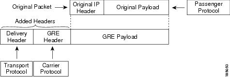
The figure shows the IP tunnel components for a GRE tunnel. The original passenger protocol packet becomes the GRE payload and the device adds a GRE header to the packet. The device then adds the transport protocol header to the packet and transmits it.
Licensing Requirements for IP Tunnels
Product |
License Requirement |
|---|---|
Cisco NX-OS |
IP tunnels require an Enterprise Services license. For a complete explanation of the Cisco NX-OS licensing scheme and how to obtain and apply licenses, see the Cisco NX-OS Licensing Guide. |
Prerequisites for IP Tunnels
IP tunnels have the following prerequisites:
Guidelines and Limitations for IP Tunnels
IP tunnels have the following configuration guidelines and limitations:
- Cisco NX-OS supports the GRE header defined in IETF RFC 2784. Cisco NX-OS does not support tunnel keys and other options from IETF RFC 1701.
- Cisco Nexus 3000 Series switch supports a maximum of eight tunnels.
-
Cisco Nexus 3000 Series switches do not support the following features: - Cisco NX-OS does not support the Web Cache Control Protocol (WCCP) on tunnel interfaces.
Default Settings for IP Tunneling
The following table lists the default settings for IP tunnel parameters.
| Parameters |
Default |
|---|---|
| Tunnel feature |
Disabled |
Configuring IP Tunnels
Enabling Tunneling
You must enable the tunneling feature before you can configure any IP tunnels.
This example shows how to enable the tunnel feature:
switch# configure terminal
switch(config)# feature tunnel
switch(config)# exit
switch(config)# copy running-config startup-config
Creating a Tunnel Interface
You can create a tunnel interface and then configure this logical interface for your IP tunnel.
Both the tunnel source and the tunnel destination must exist within the same virtual routing and forwarding ( VRF) instance.
Ensure that you have enabled the tunneling feature.
This example shows how to create a tunnel interface:
switch# configure terminal
switch(config)# interface tunnel 1
switch(config)# tunnel source ethernet 1/2
switch(config)# tunnel destination 192.0.2.1
switch(config)# copy running-config startup-config
Creating a GRE Tunnel
You can set a tunnel interface to GRE tunnel mode.
Ensure that you have enabled the tunneling feature.
This example shows how to create the tunnel interface to GRE and set the GRE tunnel keepalives:
switch# configure terminal
switch(config)# interface tunnel 1
switch(config)# tunnel mode gre ip
switch(config)# copy running-config startup-config
Assigning VRF Membership to a Tunnel Interface
You can add a tunnel interface to a VRF.
Ensure that you have enabled the tunneling feature.
Assign the IP address for a tunnel interface after you have configured the interface for a VRF.
This example shows how to add a tunnel interface to the VRF:
switch# configure terminal
switch(config)# interface tunnel 0
switch(config-if)# vrf member RemoteOfficeVRF
switch(config-if)# ip address 209.0.2.1/16
switch(config-if)# copy running-config startup-config
Verifying the IP Tunnel Configuration
To verify IP tunnel configuration information, perform one of the following tasks:
| Command | Purpose |
|---|---|
show interface tunnel number |
Displays the configuration for the tunnel interface (MTU, protocol, transport, and VRF). Displays input and output packets, bytes, and packet rates. |
show interface tunnel number brief |
Displays the operational status, IP address, encapsulation type, and MTU of the tunnel interface. |
show interface tunnel number description |
Displays the configured description of the tunnel interface. |
show interface tunnel number status |
Displays the operational status of the tunnel interface. |
show interface tunnel number status err-disabled |
Displays the error disabled status of the tunnel interface. |
Configuration Examples for IP Tunneling
This example shows a simple GRE tunnel. Ethernet 1/2 is the tunnel source for router A and the tunnel destination for router B. Ethernet interface 1/3 is the tunnel source for router B and the tunnel destination for router A.
router A:
feature tunnel
interface tunnel 0
  ip address 209.165.20.2/8
  tunnel source ethernet 1/2
  tunnel destination 192.0.2.2
  tunnel mode gre ip
interface ethernet1/2
  ip address 192.0.2.55/8

router B:
feature tunnel
interface tunnel 0
  ip address 209.165.20.1/8
  tunnel source ethernet 1/3
  tunnel destination 192.0.2.55
  tunnel mode gre ip
interface ethernet 1/3
ip address 192.0.2.2/8
Related Documents for IP Tunnels
| Related Topics | Document Title |
|---|---|
IP Tunnel commands |
Cisco Nexus 3000 Series Interfaces Command Reference |
Standards for IP Tunnels
No new or modified standards are supported by this feature, and support for existing standards has not been modified by this feature.
Feature History for Configuring IP Tunnels
Feature Name |
Release |
Feature Information |
|---|---|---|
5.0(3)U4(1) |
 Feedback