Cisco Nexus 1000V Layer 2 Switching Configuration Guide, Release 4.2(1)SV2(2.1)
Bias-Free Language
The documentation set for this product strives to use bias-free language. For the purposes of this documentation set, bias-free is defined as language that does not imply discrimination based on age, disability, gender, racial identity, ethnic identity, sexual orientation, socioeconomic status, and intersectionality. Exceptions may be present in the documentation due to language that is hardcoded in the user interfaces of the product software, language used based on RFP documentation, or language that is used by a referenced third-party product. Learn more about how Cisco is using Inclusive Language.
- Updated:
- June 24, 2013
Chapter: Overview
Overview
This chapter contains the following sections:
- Information about Layer 2 Switching
- Layer 2 Ethernet Switching
- MAC Address Tables
- VLANs
- Private VLANs
- IGMP Snooping
Information about Layer 2 Switching
VEM Port Model
The Cisco Nexus 1000V differentiates the following Virtual Ethernet Module (VEM) ports:
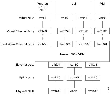
VEM Virtual Ports
The virtual side of the VEM maps together the following layers of ports:
Virtual NICs
There are three types of virtual NICs (vNICs). The vNIC is part of the Virtual Machine (VM), and represents the physical port of the host that is plugged into the switch. The internal NIC is used by the hypervisor for management,VMotion, NFS, iSCSI, and other network access. This interface would carry the IP address of the hypervisor itself, and is also bound to a virtual Ethernet port. The vswif (not shown) appears only in COS-based systems, and is used as the VMware management port. Each of these types maps to a Virtual Ethernet port within the Cisco Nexus 1000V.
Virtual Ethernet Ports
A virtual Ethernet port (vEth) represents a port on the Cisco Nexus 1000V Distributed Virtual Switch. The Cisco Nexus 1000V has a flat space of vEth ports, 1...n. These vEth ports are what the virtual cable plugs into and are moved to the host that the VM is running on. Virtual Ethernet ports are assigned to port groups.
Local Virtual Ethernet Ports
Each host has a number of local vEth (lvEth) ports. These ports are dynamically selected for vEth ports needed on the host. Local vEths do not move, and are addressable by the convention, module/port number.
VEM Physical Ports
The physical side of the VEM includes the following from top to bottom:
VMware NIC
Each physical NIC in VMware is represented by an interface called a VMNIC. The VMNIC number is allocated during VMware installation, or when a new physical NIC is installed, and remains the same for the life of the host.
Uplink Ports
Each uplink port on the host represents a physical interface. It acts a lot like an lvEth port, but since physical ports do not move between hosts, the mapping is 1:1 between an uplink port and a VMNIC.
Ethernet Ports
Each physical port that is added to the Cisco Nexus 1000V appears as a physical Ethernet port, just as it would on a hardware-based switch.
 Note | The uplink ports are handled entirely by VMware, and are used to associate port configuration with VMNICs. There is no fixed relationship between the uplink number and VMNIC number. These numbers can be different on different hosts and can change throughout the life of the host. On the VSM, the ethernet interface number, for example, ethernet 2/4, is derived from the VMNIC number, not the uplink number. |
VSM Port Model
The following figure shows the VSM view of the network.
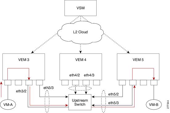
The Virtual Supervisor Module (VSM) has the following ports or interfaces:
Virtual Ethernet Interfaces
Virtual Ethernet interfaces (vEths) can be associated with any of the following:
Physical Ethernet Interfaces
Physical Ethernet interfaces (Eths) correspond to the physical NICs on the ESX host.
Port Channel Interfaces
The physical NICs of an ESX host can be bundled into a logical interface called a port channel interface.
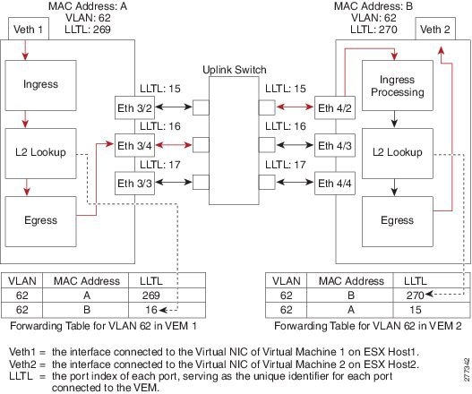
Switching Traffic Between VEMs
Each VEM that is attached to the VSM forwards traffic to and from the ESX server as an independent and intelligent line card. Each VLAN uses its forwarding table to learn and store MAC addresses for ports that are connected to the VEM.
Layer 2 Ethernet Switching
The congestion related to high bandwidth and large numbers of users can be solved by assigning each device (for example, a server) to its own 10-, 100-, 1000-Mbps, or 10-Gigabit collision domain. Because each LAN port connects to a separate Ethernet collision domain, servers in a switched environment realize full bandwidth access.
Full duplex allows two stations to transmit and receive at the same time. 10/100-Mbps Ethernet usually operates in half-duplex mode, so that stations can either receive or transmit but not both. When packets can flow in both directions simultaneously, the effective Ethernet bandwidth doubles. 1/10-Gigabit Ethernet operates in full-duplex mode only.
Each LAN port can connect to a single workstation or server or to another device through which workstations or servers connect to the network.
To reduce signal degradation, each LAN port is considered to be an individual segment. When stations connected to different LAN ports need to communicate, frames are forwarded from one LAN port to the other at wire speed to ensure full bandwidth for each session.
MAC Address Tables
To switch frames between LAN ports efficiently, a MAC address table is maintained. The MAC address of the sending network is associated with the LAN port on which it was received.
VLANs
A VLAN is a switched network that is logically segmented by function, project team, or application, without regard to the physical locations of the users. VLANs have the same attributes of physical LANs, but you can group end stations even if they are not physically located on the same LAN segment.
Any switchport can belong to a VLAN, and unicast, broadcast, and multicast packets are forwarded and flooded only to end stations in that VLAN. Each VLAN is considered a logical network, and packets destined for stations that do not belong to the VLAN must be forwarded through a bridge or a router.
All ports, including the management port, are assigned to the default VLAN (VLAN1) when the device first comes up.
Up to 4094 VLANs are supported in accordance with the IEEE 802.1Q standard.
These VLANs are organized into several ranges for different uses. Some of these VLANs are reserved for internal use by the device and are not available for configuration.
Note | Inter-Switch Link (ISL) trunking is not supported on the Cisco Nexus 1000V. |
Private VLANs
Private VLANs (PVLANs) are used to segregate Layer 2 ISP traffic and convey it to a single router interface. PVLANs achieve device isolation by applying Layer 2 forwarding constraints that allow end devices to share the same IP subnet while being Layer 2 isolated. The use of larger subnets reduces address management overhead.
IGMP Snooping
The Internet Group Management Protocol (IGMP) snooping software examines Layer 2 IP multicast traffic within a VLAN to discover the ports where interested receivers reside. Using the port information, IGMP snooping can reduce bandwidth consumption in a multi-access LAN environment to avoid flooding the entire VLAN. The IGMP snooping feature tracks which ports are attached to multicast-capable routers to help the routers forward IGMP membership reports. The IGMP snooping software responds to topology change notifications. By default, IGMP snooping is enabled on the device.
 Feedback