Cisco Nexus 1010 Software Configuration Guide, Release 4.2(1) SP1(2)
Bias-Free Language
The documentation set for this product strives to use bias-free language. For the purposes of this documentation set, bias-free is defined as language that does not imply discrimination based on age, disability, gender, racial identity, ethnic identity, sexual orientation, socioeconomic status, and intersectionality. Exceptions may be present in the documentation due to language that is hardcoded in the user interfaces of the product software, language used based on RFP documentation, or language that is used by a referenced third-party product. Learn more about how Cisco is using Inclusive Language.
- Updated:
- January 31, 2011
Chapter: Setting up the Management Software
Setting Up the Management Software
This chapter describes how to set up the system management software and includes the following sections:
•![]() Information About the Management Software
Information About the Management Software
•![]() Setting Up the Management Software
Setting Up the Management Software
•![]() Verifying the Setup Configuration
Verifying the Setup Configuration
•![]() Feature History for Management Software Setup
Feature History for Management Software Setup
Information About the Management Software
The system setup routine lets you configure the following information for your Cisco Nexus 1010:
Administrator Credentials
When you set up the system software, you are required to create an administrator password. Table 2-1 lists password strength guidelines:
HA Redundancy Role
The Cisco Nexus 1010 is provided in redundant pairs for high availability. When setting up the device, you configure a high availability role—primary or secondary. Table 2-2 describes these roles.

Note ![]() The HA standalone role is not supported for the Cisco Nexus 1010.
The HA standalone role is not supported for the Cisco Nexus 1010.
HA Redundancy States
Table 2-3 describes the HA redundancy states.
Domain ID
The primary and secondary Cisco Nexus 1010s use the domain ID to identify each other. The Cisco Nexus 1010s must be in the same switching domain, and share the same management IP address.
Uplinks
You can connect your system to the network using one of the following four supported uplink types.
•![]() One uplink
One uplink
•![]() Two uplinks with common management and control traffic
Two uplinks with common management and control traffic
•![]() Two uplinks with common control and data traffic
Two uplinks with common control and data traffic
•![]() Three uplinks
Three uplinks
Note ![]() Once you configure an uplink type, the only way to modify it is to reload the software.
Once you configure an uplink type, the only way to modify it is to reload the software.
Table 2-4 shows the four supported network uplink types and the ports that carry each type of VLAN traffic.
For more information about uplinks, see the "Uplinks" section.
VLANs
Control, and management VLANs are used by the Cisco Nexus 1010 for management and communication with its virtual service blades. These VLANs are added as a part of the initial setup of the management software. Control and packet VLANs are also added to each virtual service blade when it is created. The management VLAN is inherited from the Cisco Nexus 1010 by each virtual service blade.
If you modify a control, packet, or management VLAN on the Cisco Nexus 1010, the change is effective immediately. However, for service continuity, you must configure the same control and packet VLANs on the hosted VSMs. Otherwise the Cisco Nexus 1010 loses communication with its VSMs.
This section includes the following additional topics:
Management VLAN
The management VLAN is the VLAN that forwards traffic for the management port of the Cisco Nexus 1010. If your virtual service blade uses the management class of traffic, it inherits the management VLAN from the Cisco Nexus 1010.
The management VLAN is used by the outside world to reach the Cisco Nexus 1010 management 0 interface. The Cisco Nexus 1010 and its hosted Cisco Nexus 1000V VSMs share the same management VLAN. Unlike the control and packet VLANs which are set when a virtual service blade is created, the management VLAN is inherited from the Cisco Nexus 1010 by all virtual service blades it hosts.
Control VLAN
The control VLAN is a Layer 2 interface used for communication between the redundant Cisco Nexus 1010s. This interface handles low-level control packets such as heartbeats as well as any configuration data that needs to be exchanged between the Cisco Nexus 1010s.
Guidelines and Limitations
Follow these guidelines and limitations when setting up the Cisco Nexus 1010:
•![]() The domain ID must be unique within the VLAN.
The domain ID must be unique within the VLAN.
•![]() If other Cisco Nexus 1010s or Cisco Nexus 1000Vs are in the same VLAN, then the domain ID must also be unique across all of them.
If other Cisco Nexus 1010s or Cisco Nexus 1000Vs are in the same VLAN, then the domain ID must also be unique across all of them.
•![]() When setting up the software, you configure the uplink type for your system. Once you configure an uplink type, the only way to modify it is to reload the software.
When setting up the software, you configure the uplink type for your system. Once you configure an uplink type, the only way to modify it is to reload the software.
•![]() The HA standalone role is not supported for the Cisco Nexus 1010.
The HA standalone role is not supported for the Cisco Nexus 1010.
It is a recommended Cisco best practice to configure a primary Cisco Nexus 1010 with a secondary backup. Although you can configure a primary Cisco Nexus 1010 without a secondary backup, this configuration in a production environment is not recommended.
Setting Up the Management Software
Use the following procedures to setup the software for configuring and managing the Cisco Nexus 1010 system.
•![]() Setting up the Primary Cisco Nexus 1010
Setting up the Primary Cisco Nexus 1010
•![]() Setting up the Secondary Cisco Nexus 1010
Setting up the Secondary Cisco Nexus 1010
BEFORE YOU BEGIN
Before beginning the procedures in this section, you must know or do the following:
•![]() You have already installed the Cisco Nexus 1010 hardware and you are logged in to the Cisco Nexus 1010 CLI. Once you are logged in, the setup wizard starts.
You have already installed the Cisco Nexus 1010 hardware and you are logged in to the Cisco Nexus 1010 CLI. Once you are logged in, the setup wizard starts.
–![]() Login from a terminal server:
Login from a terminal server:
Example:
telnet 172.25.182.99 2005
Trying 172.25.182.99...
Connected to 172.25.182.99.
Escape character is '^]'
switch#
---- System Admin Account Setup ----
Enter the password for "admin":
Confirm the password for"admin":
–![]() Login from a serial over LAN connection through CIMC:
Login from a serial over LAN connection through CIMC:
Example:
ssh admin@172.25.182.230
admin@172.25.182.230's password:
switch# connect host
CISCO Serial Over LAN:
Close Network Connection to Exit
---- System Admin Account Setup ---- Enter the password for "admin":Confirm the password for"admin":
For detailed information about connecting to the Cisco Nexus 1010, see the Cisco Nexus 1010 Virtual Services Appliance Hardware Installation Guide.
•![]() You have the following information available for this Cisco Nexus 1010:
You have the following information available for this Cisco Nexus 1010:
–![]() Administrator password
Administrator password
–![]() HA role (primary or secondary)
HA role (primary or secondary)
If you do not specify an HA role, then the role is configured as primary.
Note ![]() The HA standalone role is not supported for the Cisco Nexus 1010.
The HA standalone role is not supported for the Cisco Nexus 1010.
–![]() Network uplink type
Network uplink type
–![]() Control VLAN ID
Control VLAN ID
–![]() Domain ID
Domain ID
–![]() Management VLAN ID
Management VLAN ID
–![]() Management 0 IP address
Management 0 IP address
This is the IP address of the management interface that appears as the mgmt0 port on the appliance.
–![]() Default gateway IP address
Default gateway IP address
–![]() SSH service key type and number of key bits
SSH service key type and number of key bits
Setting up the Primary Cisco Nexus 1010
You can use this procedure to set up the management software for either of the following:
•![]() The primary Cisco Nexus 1010 in a redundant HA pair
The primary Cisco Nexus 1010 in a redundant HA pair
•![]() A single Cisco Nexus 1010
A single Cisco Nexus 1010
It is a recommended Cisco best practice to configure a primary Cisco Nexus 1010 with a secondary backup. Although you can configure a primary Cisco Nexus 1010 without a secondary backup, this configuration in a production environment is not recommended.
DETAILED STEPS
Step 1 ![]() Use one of the following methods to log in to the Cisco Nexus 1010 CLI.
Use one of the following methods to log in to the Cisco Nexus 1010 CLI.
The setup wizard starts automatically.
•![]() Login from a terminal server:
Login from a terminal server:
Example:
telnet 172.25.182.99 2005
Trying 172.25.182.99...
Connected to 172.25.182.99.
Escape character is '^]'
switch#
---- System Admin Account Setup ---- Enter the password for "admin":Confirm the password for"admin":
•![]() Login from a serial over LAN connection through CIMC:
Login from a serial over LAN connection through CIMC:
Example:
ssh admin@172.25.182.230
admin@172.25.182.230's password:
switch# connect host
CISCO Serial Over LAN:
Close Network Connection to Exit
---- System Admin Account Setup ---- Enter the password for "admin":Confirm the password for"admin":
Step 2 ![]() When asked, enter and confirm the Administrator password.
When asked, enter and confirm the Administrator password.
Example:
---- System Admin Account Setup ----Confirm the password for
Enter the password for "admin": "admin":
Step 3 ![]() When asked, enter the HA role. If you do not specify a role, then primary is assigned.
When asked, enter the HA role. If you do not specify a role, then primary is assigned.
Example:
Enter HA role[primary/secondary]: primary
Note ![]() The HA standalone role is not supported for the Cisco Nexus 1010.
The HA standalone role is not supported for the Cisco Nexus 1010.
Step 4 ![]() When asked, enter the uplink type.
When asked, enter the uplink type.
Note ![]() Once you configure an uplink type, the only way to modify it is to reload the software.
Once you configure an uplink type, the only way to modify it is to reload the software.
Example:
Enter network-uplink type <1-4>:
1. Ports 1-2 carry all management, control and data vlans
2. Ports 1-2 management and control, ports 3-6 data
3. Ports 1-2 management, ports 3-6 control and data
4. Ports 1-2 management, ports 3-4 control, ports 5-6 data
1
Step 5 ![]() When asked, enter the VLAN ID for the control VLAN.
When asked, enter the VLAN ID for the control VLAN.
Example:
Enter control vlan <1-3967, 4048-4093>: 300
Step 6 ![]() When asked, enter the domain ID.
When asked, enter the domain ID.
Example:
Enter the domain id<1-4095>: 300
Step 7 ![]() When asked, enter the VLAN ID for the management VLAN.
When asked, enter the VLAN ID for the management VLAN.
The new configuration is saved into nonvolatile storage, after which the running and the startup copies of the configuration are identical.
Example:
Enter management vlan <1-3967, 4048-4093>: 233
Saving boot configuration. Please wait...
[########################################] 100%
---- Basic System Configuration Dialog ----
This setup utility will guide you through the basic configuration of the system. Setup
configures only enough connectivity for management of the system.
Press Enter at anytime to skip a dialog. Use ctrl-c at anytime to skip the remaining
dialogs.
Step 8 ![]() When asked if you want to enter the basic configuration dialog, respond yes.
When asked if you want to enter the basic configuration dialog, respond yes.
Example:
Would you like to enter the basic configuration dialog (yes/no): yes
---- Basic System Configuration Dialog ----
This setup utility will guide you through the basic configuration of
the system. Setup configures only enough connectivity for management
of the system.
*Note: setup is mainly used for configuring the system initially,
when no configuration is present. So setup always assumes system
defaults and not the current system configuration values.
Press Enter at anytime to skip a dialog. Use ctrl-c at anytime
to skip the remaining dialogs.
Step 9 ![]() When asked to create another Login account, answer no.
When asked to create another Login account, answer no.
Example:
Create another login account (yes/no) [n]: no
Step 10 ![]() When asked to configure a read-only SNMP community string, answer no.
When asked to configure a read-only SNMP community string, answer no.
Example:
Configure read-only SNMP community string (yes/no) [n]: no
Step 11 ![]() When asked to configure a read-write SNMP community string, answer no.
When asked to configure a read-write SNMP community string, answer no.
Example:
Configure read-write SNMP community string (yes/no) [n]:
Step 12 ![]() Enter a name for the appliance.
Enter a name for the appliance.
Example:
Enter the VSA name [Nexus1010]:
Step 13 ![]() When asked to configure out-of-band management, answer yes and then enter the management 0 IPv4 address.
When asked to configure out-of-band management, answer yes and then enter the management 0 IPv4 address.
This is the IP address of the management interface that appears as the mgmt0 port on the appliance.
Example:
Continue with Out-of-band (mgmt0) management configuration? [yes/no] [y]: yes
Mgmt0 IPv4 address: 10.78.109.67
Step 14 ![]() When asked to configure the default gateway, answer yes.
When asked to configure the default gateway, answer yes.
Example:
Configure the default-gateway: (yes/no) [y]: yes
IPv4 address of the default gateway : 10.78.109.65
Step 15 ![]() When asked to configure advanced IP options, answer no.
When asked to configure advanced IP options, answer no.
Example:
Configure Advanced IP options (yes/no)? [n]: no
Step 16 ![]() When asked to enable the Telnet service, answer yes.
When asked to enable the Telnet service, answer yes.
Example:
Enable the telnet service? (yes/no) [y]: yes
Step 17 ![]() When asked to enable the SSH service, answer yes and then enter the key type and number of key bits.
When asked to enable the SSH service, answer yes and then enter the key type and number of key bits.
Example:
Enable the ssh service? (yes/no) [y]: yes
Type of ssh key you would like to generate (dsa/rsa) : rsa
Number of  key bits <768-2048> : 1024
Step 18 ![]() When asked to configure the NTP server, answer no.
When asked to configure the NTP server, answer no.
The configuration is summarized.
Example:
Configure NTP server? (yes/no) [n]: no
The following configuration will be applied:
Switchname n1010
interface Mgmt0
ip address 172.28.15.152 255.255.255.0
no shutdown
telnet server enable
ssh key rsa 1024 force
ssh server enable
svs-domain
control vlan 260
domain id 152
Step 19 ![]() Do one of the following:
Do one of the following:
•![]() If you do not want to edit the configuration answer no and continue with the next step.
If you do not want to edit the configuration answer no and continue with the next step.
•![]() If you want to edit the configuration, answer yes and return to Step 9 to revisit each command.
If you want to edit the configuration, answer yes and return to Step 9 to revisit each command.
Example:
Would you like to edit the configuration? (yes/no) [n]:no
Step 20 ![]() When asked to use and save this configuration, answer yes.
When asked to use and save this configuration, answer yes.

Example:
Use this configuration and save it? (yes/no) [y]: yes
[########################################] 100%
The new configuration is saved into nonvolatile storage, after which the running and the startup copies of the configuration are identical.
Note ![]() You can use the setup routine to update the configuration done in Step 9 through Step 20 at any time by entering the setup command in EXEC mode. Once setup begins, press Enter to skip a command. Use ctrl-c to skip the remaining commands.
You can use the setup routine to update the configuration done in Step 9 through Step 20 at any time by entering the setup command in EXEC mode. Once setup begins, press Enter to skip a command. Use ctrl-c to skip the remaining commands.
Step 21 ![]() You have completed this procedure. Continue with the "Verifying the Setup Configuration" procedure.
You have completed this procedure. Continue with the "Verifying the Setup Configuration" procedure.
Setting up the Secondary Cisco Nexus 1010
You can use this procedure to set up the management software for the secondary Cisco Nexus 1010 in a redundant pair.
DETAILED STEPS
Step 1 ![]() When asked, enter and confirm the Administrator password.
When asked, enter and confirm the Administrator password.
Example:
---- System Admin Account Setup ----Confirm the password for
Enter the password for "admin": "admin":
Step 2 ![]() When asked, enter the HA role.
When asked, enter the HA role.
Example:
Enter HA role[primary/secondary]: secondary
Step 3 ![]() When asked, enter the uplink type.
When asked, enter the uplink type.
Note ![]() Once you configure an uplink type, the only way to modify it is to reload the software.
Once you configure an uplink type, the only way to modify it is to reload the software.
Example:
Enter network-uplink type <1-4>:
1. Ports 1-2 carry all management, control and data vlans
2. Ports 1-2 management and control, ports 3-6 data
3. Ports 1-2 management, ports 3-6 control and data
4. Ports 1-2 management, ports 3-4 control, ports 5-6 data
1
Step 4 ![]() When asked, enter the VLAN ID for the control VLAN.
When asked, enter the VLAN ID for the control VLAN.
Example:
Enter control vlan <1-3967, 4048-4093>: 300
Step 5 ![]() When asked, enter the domain ID.
When asked, enter the domain ID.
Example:
Enter the domain id<1-4095>: 300
Step 6 ![]() When asked, enter the VLAN ID for the management VLAN.
When asked, enter the VLAN ID for the management VLAN.
The following things occur on the switch:
•![]() The new configuration is saved into nonvolatile storage, after which the running and the startup copies of the configuration are identical.
The new configuration is saved into nonvolatile storage, after which the running and the startup copies of the configuration are identical.
•![]() The system reboots to configure the network uplinks.
The system reboots to configure the network uplinks.
•![]() The system restarts and synchronizes its configuration with the primary Cisco Nexus 1000V.
The system restarts and synchronizes its configuration with the primary Cisco Nexus 1000V.
Example:
Enter management vlan <1-3967, 4048-4093>: 233
Saving boot configuration. Please wait...
[########################################] 100%
System is going to reboot to configure network uplinks
HA mode set to secondary. Rebooting now...
Step 7 ![]() You have completed this procedure. Continue with the "Verifying the Setup Configuration" procedure.
You have completed this procedure. Continue with the "Verifying the Setup Configuration" procedure.
Replacing a Cisco Nexus 1010
You can replace one Cisco Nexus 1010 in a redundant pair using the process described in Figure 2-1 on the next page.
BEFORE YOU BEGIN
Before setting up the software for a replacement Cisco Nexus 1010, you must know or do the following:
•![]() The HA role of the functioning Cisco Nexus 1010 determines the role assigned to the replacement Cisco Nexus 1010.
The HA role of the functioning Cisco Nexus 1010 determines the role assigned to the replacement Cisco Nexus 1010.
–![]() If the functioning Cisco Nexus 1010 is in the primary HA role, the software for the replacement Cisco Nexus 1010 must be set up in the secondary HA role.
If the functioning Cisco Nexus 1010 is in the primary HA role, the software for the replacement Cisco Nexus 1010 must be set up in the secondary HA role.
–![]() If the functioning Cisco Nexus 1010 is in the secondary HA role, the software for the replacement Cisco Nexus 1010 must be set up in the primary HA role.
If the functioning Cisco Nexus 1010 is in the secondary HA role, the software for the replacement Cisco Nexus 1010 must be set up in the primary HA role.
•![]() When setting up the software for the replacement Cisco Nexus 1010, you must use the same IDs used on the functioning Cisco Nexus 1010 for the following:
When setting up the software for the replacement Cisco Nexus 1010, you must use the same IDs used on the functioning Cisco Nexus 1010 for the following:
–![]() Domain
Domain
–![]() Control VLAN
Control VLAN
–![]() Management VLAN
Management VLAN
•![]() The software versions running on the functioning Cisco Nexus 1010 and the replacement Cisco Nexus 1010 must match. The replacement Cisco Nexus 1010 ships with the latest software version installed.
The software versions running on the functioning Cisco Nexus 1010 and the replacement Cisco Nexus 1010 must match. The replacement Cisco Nexus 1010 ships with the latest software version installed.
–![]() If you want to downgrade the software version on the replacement Cisco Nexus 1010, use the reinstall procedure in the Cisco Nexus 1010 Software Installation and Upgrade Guide, Release 4.2(1)SP1(2).
If you want to downgrade the software version on the replacement Cisco Nexus 1010, use the reinstall procedure in the Cisco Nexus 1010 Software Installation and Upgrade Guide, Release 4.2(1)SP1(2).
–![]() If you want to upgrade the software on one of the Cisco Nexus 1010s, use the upgrade procedure in the Cisco Nexus 1010 Software Installation and Upgrade Guide, Release 4.2(1)SP1(2).
If you want to upgrade the software on one of the Cisco Nexus 1010s, use the upgrade procedure in the Cisco Nexus 1010 Software Installation and Upgrade Guide, Release 4.2(1)SP1(2).
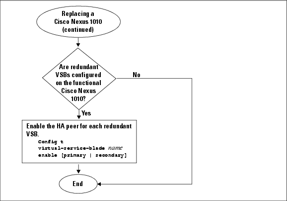
•![]() After you set up the software for the replacement Cisco Nexus 1010, you must manually enable the HA peer for each redundant virtual service blade (VSB).
After you set up the software for the replacement Cisco Nexus 1010, you must manually enable the HA peer for each redundant virtual service blade (VSB).
–![]() If the functioning Cisco Nexus 1010 is in the primary HA role, enable the secondary HA peer for each redundant VSB.
If the functioning Cisco Nexus 1010 is in the primary HA role, enable the secondary HA peer for each redundant VSB.
Config t
virtual-service-blade name
enable secondary
–![]() If the functioning Cisco Nexus 1010 is in the secondary HA role, enable the primary HA peer for each redundant VSB.
If the functioning Cisco Nexus 1010 is in the secondary HA role, enable the primary HA peer for each redundant VSB.
Config t
virtual-service-blade name
enable primary
Figure 2-1 Flow Chart: Replacing a Cisco Nexus 1010
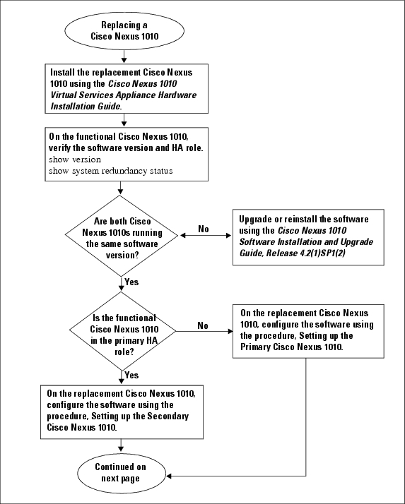
Figure 2-2 Flow Chart: Replacing a Cisco Nexus 1010 (continued)
Verifying the Setup Configuration
To verify the Cisco Nexus 1010 setup configuration, use the following commands:
|
|
|
|---|---|
show running-configuration |
Displays the Cisco Nexus 1010 running configuration. See Example 2-1. |
show system redundancy status |
Displays the redundancy state (active or standby) and the redundancy role (primary or secondary) for the Cisco Nexus 1010s. See Example 2-2. |
show svs domain |
Displays the following domain information for the Cisco Nexus 1010: • • • See Example 2-3. |
Example 2-1 Setup Configuration
This example shows how to display and verify the Cisco Nexus 1010 setup configuration:
Nexus1010# show running-config
version 4.2(1)SV1(4)
username adminbackup password 5 $1$Oip/C5Ci$oOdx7oJSlBCFpNRmQK4na. role network-operato
r
username admin password 5 $1$ZMouammW$56jYJfpQuDJjDen5MABcW/ role network-admin
telnet server enable
ip domain-lookup
ip host Nexus1010 172.23.231.113
kernel core target 0.0.0.0
kernel core limit 1
system default switchport
snmp-server user admin network-admin auth md5 0xb64ad6879970f0e57600c443287a79f0 priv 0x
b64ad6879970f0e57600c443287a79f0 localizedkey
snmp-server enable traps license
vrf context management
ip route 0.0.0.0/0 172.23.231.1
switchname Nexus1010
vlan 1,231,233,280,300
vdc Nexus1010 id 1
limit-resource vlan minimum 16 maximum 513
limit-resource monitor-session minimum 0 maximum 64
limit-resource vrf minimum 16 maximum 8192
limit-resource port-channel minimum 0 maximum 256
limit-resource u4route-mem minimum 32 maximum 80
limit-resource u6route-mem minimum 16 maximum 48
network-uplink type 1
interface mgmt0
ip address 172.23.231.113/24
interface control0
boot kickstart bootflash:/nexus-1010-kickstart-mzg.4.2.1.SP1.2.bin
boot system bootflash:/nexus-1010-mzg.4.2.1.SP1.2.bin
boot kickstart bootflash:/nexus-1010-kickstart-mzg.4.2.1.SP1.2.bin
boot system bootflash:/nexus-1010-mzg.4.2.1.SP1.2.bin
svs-domain
domain id 2801
control vlan 300
management vlan 233
svs mode L2
Example 2-2 Redundancy Status
switch# show system redundancy status
Redundancy role
---------------
administrative: primary
operational: primary
Redundancy mode
---------------
administrative: HA
operational: None
This supervisor (sup-1)
-----------------------
Redundancy state: Active
Supervisor state: Active
Internal state: Active with no standby
Other supervisor (sup-2)
------------------------
Redundancy state: Not present
switch#
---- ----
Example 2-3 Domain
switch# show svs domain
SVS domain config:
Domain id: 3555
Control vlan: 305
Management vlan: 233
L2/L3 Control mode: L2
L3 control interface: NA
Status: Config not pushed to VC.
switch#
Example Configurations
The following is an example of a complete setup configuration for a primary in a pair of redundant pair or a single Cisco Nexus 1000V.
---- System Admin Account Setup ----Confirm the password for
Enter the password for "admin": "admin":
Enter HA role[primary/secondary]: primary
Enter network-uplink type <1-4>:
1. Ports 1-2 carry all management, control and data vlans
2. Ports 1-2 management and control, ports 3-6 data
3. Ports 1-2 management, ports 3-6 control and data
4. Ports 1-2 management, ports 3-4 control, ports 5-6 data
1
Enter control vlan <1-3967, 4048-4093>: 300
Enter the domain id<1-4095>: 300
Enter management vlan <1-3967, 4048-4093>: 233
Saving boot configuration. Please wait...
[########################################] 100%
---- Basic System Configuration Dialog ----
This setup utility will guide you through the basic configuration of
the system. Setup configures only enough connectivity for management
of the system.
Press Enter at anytime to skip a dialog. Use ctrl-c at anytime
to skip the remaining dialogs.
Would you like to enter the basic configuration dialog (yes/no): yes
Create another login account (yes/no) [n]:
Configure read-only SNMP community string (yes/no) [n]:
Configure read-write SNMP community string (yes/no) [n]:
Enter the VSA name : CPPAPrimary
Continue with Out-of-band (mgmt0) management configuration? (yes/no) [y]:
Mgmt0 IPv4 address : 10.78.110.111
Mgmt0 IPv4 netmask : 255.255.255.128
Configure the default gateway? (yes/no) [y]:
IPv4 address of the default gateway : 10.78.110.17
Configure advanced IP options? (yes/no) [n]:
Enable the telnet service? (yes/no) [y]:
Enable the ssh service? (yes/no) [n]: yes
Type of ssh key you would like to generate (dsa/rsa) : rsa
Number of key bits <768-2048> : 1024
Configure the ntp server? (yes/no) [n]:
The following configuration will be applied:
switchname CPPAPrimary
interface mgmt0
ip address 10.78.110.111 255.255.255.128
no shutdown
vrf context management
ip route 0.0.0.0/0 10.78.110.17
telnet server enable
ssh key rsa 1024 force
ssh server enable
Would you like to edit the configuration? (yes/no) [n]:
Use this configuration and save it? (yes/no) [y]:
[########################################] 100%
System is going to reboot to configure network uplinks
The following is an example of a complete setup configuration for the secondary in a pair of redundant of Cisco Nexus 1000Vs.
---- System Admin Account Setup ----Confirm the password for
Enter the password for "admin": "admin":
Enter HA role[primary/secondary]: primary
Enter HA role[primary/secondary]: primary
Enter network-uplink type <1-4>:
1. Ports 1-2 carry all management, control and data vlans
2. Ports 1-2 management and control, ports 3-6 data
3. Ports 1-2 management, ports 3-6 control and data
4. Ports 1-2 management, ports 3-4 control, ports 5-6 data
1
Enter control vlan <1-3967, 4048-4093>: 459
Enter the domain id<1-4095>: 459
Enter management vlan <1-3967, 4048-4093>: 460
Saving boot configuration. Please wait...
[########################################] 100%
System is going to reboot to configure network uplinks
HA mode set to secondary. Rebooting now...
Additional References
For additional information related to implementing system-level HA features, see the following sections:
•![]() RFCs
RFCs
Related Documents
Standards
|
|
|
|---|---|
No new or modified standards are supported by this feature, and support for existing standards has not been modified by this feature. |
— |
RFCs
|
|
|
|---|---|
No RFCs are supported by this feature |
— |
Feature History for Management Software Setup
This section provides the management software setup release history.
|
|
|
|
|---|---|---|
software setup |
4.0(4)SP1(1) |
This feature was introduced. |
 Feedback