- Preface
- Troubleshooting Overview
- Troubleshooting Tools
- Troubleshooting the Installation
- Troubleshooting the Licensing
- Troubleshooting Modules
- Troubleshooting Ports and Port Profiles
- Troubleshooting Port Channels and Trunking
- Troubleshooting Layer 2 Switching
- Troubleshooting ACLs
- Troubleshooting QoS
- Troubleshooting Netflow
- Troubleshooting VLANs
- Troubleshooting PVLANs
- Troubleshooting Multicast IGMP Issues
- Troubleshooting SPAN
- Troubleshooting High Availability
- Troubleshooting System Issues
- Before Contacting Technical Support
- Index
Cisco Nexus 1000V Troubleshooting Guide, Release 4.0(4)SV(1)
Bias-Free Language
The documentation set for this product strives to use bias-free language. For the purposes of this documentation set, bias-free is defined as language that does not imply discrimination based on age, disability, gender, racial identity, ethnic identity, sexual orientation, socioeconomic status, and intersectionality. Exceptions may be present in the documentation due to language that is hardcoded in the user interfaces of the product software, language used based on RFP documentation, or language that is used by a referenced third-party product. Learn more about how Cisco is using Inclusive Language.
- Updated:
- May 20, 2009
Chapter: Troubleshooting Modules
Modules
This chapter describes how to identify and resolve problems that relate to modules.
This chapter includes the following sections:
•![]() Troubleshooting a Module Not Coming Up on the VSM
Troubleshooting a Module Not Coming Up on the VSM
Information About Modules
Cisco Nexus 1000V manages a data center defined by a VirtualCenter. Each server in the data center is represented as a module in the Cisco Nexus 1000V and can be managed as if it were a module in a physical Cisco switch.
The Cisco Nexus 1000V implementation consists of two parts:
•![]() Virtual supervisor module (VSM) - This is the control software of the Cisco Nexus 1000V distributed virtual switch. It runs on a virtual machine (VM) and is based on NX-OS software.
Virtual supervisor module (VSM) - This is the control software of the Cisco Nexus 1000V distributed virtual switch. It runs on a virtual machine (VM) and is based on NX-OS software.
•![]() Virtual Ethernet module (VEM) - This is the part of Cisco Nexus 1000V that actually switches data traffic. It runs on a VMware ESX 4.0 host. Several VEMs are controlled by one VSM. All the VEMs that form a switch domain should be in the same virtual Data Center as defined by VMware VirtualCenter.
Virtual Ethernet module (VEM) - This is the part of Cisco Nexus 1000V that actually switches data traffic. It runs on a VMware ESX 4.0 host. Several VEMs are controlled by one VSM. All the VEMs that form a switch domain should be in the same virtual Data Center as defined by VMware VirtualCenter.
Table 5-1 lists the terminology used in the Cisco Nexus 1000V implementation.
Troubleshooting a Module Not Coming Up on the VSM
Troubleshooting a module that does not come up on the VSM is a multi-step process. Before you start this process, ensure that you follow the guidelines described in the following section.
Guidelines
Follow these guidelines when troubleshooting a module for the VSM.
•![]() You must have a VSM VM and a VEM up and running. Make sure you are running the correct versions of vCenter Server and VSM.
You must have a VSM VM and a VEM up and running. Make sure you are running the correct versions of vCenter Server and VSM.
•![]() To verify the network connectivity between the VSM and vCenter Server, ping the IP address of the vCenter Server. If you are using a domain name service (DNS) name, use the DNS name in the ping. If a ping to the vCenter Server fails, check to see if you can ping the gateway. Otherwise, check the mgmt0 interface configuration settings.
To verify the network connectivity between the VSM and vCenter Server, ping the IP address of the vCenter Server. If you are using a domain name service (DNS) name, use the DNS name in the ping. If a ping to the vCenter Server fails, check to see if you can ping the gateway. Otherwise, check the mgmt0 interface configuration settings.
•![]() Make sure the firewall settings are OFF on the vCenter Server. If you want the firewall settings, then check to see if these ports are open.
Make sure the firewall settings are OFF on the vCenter Server. If you want the firewall settings, then check to see if these ports are open.
–![]() Port 80
Port 80
–![]() Port 443
Port 443
•![]() If you see the error "ERROR: [VMware vCenter Server 4.0.0 build-150489] Extension key was not registered before its use." To check if the VSM extension was created from vCenter Server, point your web browser to: https://your-virtual-center/mob/. Click:
If you see the error "ERROR: [VMware vCenter Server 4.0.0 build-150489] Extension key was not registered before its use." To check if the VSM extension was created from vCenter Server, point your web browser to: https://your-virtual-center/mob/. Click:
–![]() Content
Content
–![]() ExtensionManager
ExtensionManager
•![]() You should see an entry for Cisco_Nexus_1000v_nnnnnn. For more information, see the Cisco Nexus 1000V Software Installation Guide, Release 4.0(4)SV1(1).
You should see an entry for Cisco_Nexus_1000v_nnnnnn. For more information, see the Cisco Nexus 1000V Software Installation Guide, Release 4.0(4)SV1(1).
•![]() If the error is ERROR: Datacenter not found, check to see if the datacenter exists in the vCenter Server.
If the error is ERROR: Datacenter not found, check to see if the datacenter exists in the vCenter Server.
Troubleshooting Procedure
Use the following flowchart to isolate problems with a module not coming up on the VSM.
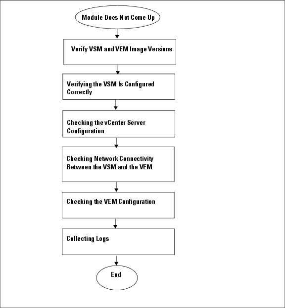
The following sections provide steps to follow, if the output of the show module command does not display the module.
Verifying the VSM Is Connected to the vCenter Server
To check if the VSM is connected to the vCenter Server follow this step:
Step 1 ![]() Enter the show svs connections command to confirm that the VSM is connected to the vCenter Server.
Enter the show svs connections command to confirm that the VSM is connected to the vCenter Server.
n1000v# show svs connections
connection vc:
ip address: 172.23.231.223
protocol: vmware-vim https
certificate: user-installed
datacenter name: sean-dc
DVS uuid: 92 7a 14 50 05 11 15 9c-1a b0 f2 d4 8a d7 6e 6c
config status: Disabled
operational status: Disconnected
Step 2 ![]() If operation status is Disconnected rather than Connected, then connect to the vCenter Server using the following commands:
If operation status is Disconnected rather than Connected, then connect to the vCenter Server using the following commands:
n1000v# conf t
n1000v(config)# svs connection HamiltonDC
n1000v(config-svs-conn)# connect
If the connect operation fails with the error Extension key was not registered, then it is possible the SSL certificates do not match.
n1000v(config-svs-conn)# connect
ERROR: [VMWARE-VIM] Extension key was not registered before its use.
The Cisco Nexus 1000V VSM uses an SSL certificate when communicating with the VMware vCenter Server. The certificate is part of the extension that is registered on the vCenter Server. If the certificate in the extension that was registered does not match the certificate that the VSM is using, then any attempt to connect to the vCenter Server will fail.
This situation can arise when the extension is registered on the vCenter Server and the user changes the certificate being used by the VSM using the install certificate command. Additionally, if the user issues the vmware vc extension-key extension-key command, the default certificate that the VSM uses will be regenerated. Therefore, if the VSM is using the default certificate, then the SSL certificate on the VSM will not match the certificate registered on the vCenter Server.
The solution is to remove the existing extension from the vCenter Server, download the extension file from the VSM (for example, from http://vsm-ip/cisco_nexus_1000v_extension.xml), and register the new extension on the vCenter Server.
Verifying the VSM Is Configured Correctly
To check if the VSM is configured correctly, follow these steps:
Step 1 ![]() Confirm that you have configured the domain ID, the control VLAN, and packet VLAN as specified in the svs-domain configuration. Enter the show svs domain command to display the status. It should be Config push to vCenter Server successful.
Confirm that you have configured the domain ID, the control VLAN, and packet VLAN as specified in the svs-domain configuration. Enter the show svs domain command to display the status. It should be Config push to vCenter Server successful.
n1000v# show svs domain
SVS domain config:
Domain id: 682
Control vlan: 3002
Packet vlan: 3003
L2/L3 Control VLAN mode: L2
L2/L3 Control VLAN interface: mgmt0
Status: Config push to VC successful
Step 2 ![]() Confirm that you have configured the system profile correctly, as shown in the following example:
Confirm that you have configured the system profile correctly, as shown in the following example:
port-profile system-uplink
switchport mode trunk
system vlan 3002-3003
switchport trunk allowed vlan 3002-3003
vmware port-group uplinkportprofile1
no shutdown
capability uplink
state enabled
The system VLAN should include the control and packet VLANs. Capability should be uplink, and state should be enabled.
Step 3 ![]() Check if VLANs 3002 and 3003 are created on the VSM. Enter the show running-config command to see if the following line is available:
Check if VLANs 3002 and 3003 are created on the VSM. Enter the show running-config command to see if the following line is available:
n1000v# show running-config
vlan 3002-3003
Checking the vCenter Server Configuration
To check the configuration on the vCenter Server, follow these steps:
Step 1 ![]() Confirm that the host is added to the HamiltonDC and the n1000V DVS in that data center.
Confirm that the host is added to the HamiltonDC and the n1000V DVS in that data center.
Step 2 ![]() Confirm that at least one pnic of the host is added to the DVS, and that pnic is assigned to the system-uplink profile.
Confirm that at least one pnic of the host is added to the DVS, and that pnic is assigned to the system-uplink profile.
Step 3 ![]() Confirm that the three VSM vnics are assigned to the port groups containing the control VLAN, packet VLAN, and management network.
Confirm that the three VSM vnics are assigned to the port groups containing the control VLAN, packet VLAN, and management network.
Checking Network Connectivity Between the VSM and the VEM
To ensure that there is L2 network connectivity between the VSM and the VEM, follow these steps:
Step 1 ![]() On the VSM, enter the show svs neighbors command and make sure that the user VEM Agent MAC address of the host appears in the output. (The vemcmd show card info command displays the user VEM Agent MAC address of the host.)
On the VSM, enter the show svs neighbors command and make sure that the user VEM Agent MAC address of the host appears in the output. (The vemcmd show card info command displays the user VEM Agent MAC address of the host.)
n1000v# show svs neighbors
Active Domain ID: 11
Src MAC Type Domain-id Node-id Last learnt (Sec. ago)
------------------------------------------------------------------------
0002-3d40-0b0c DP 152 0300 266233.26
Step 2 ![]() Enter the appropriate mac address-table commands on the upstream switches to verify the network configuration.
Enter the appropriate mac address-table commands on the upstream switches to verify the network configuration.
n1000v#show mac address-table interface Gi3/1 vlan 3002
Legend: * - primary entry
age - seconds since last seen
n/a - not available
vlan mac address type learn age ports
------+----------------+--------+-----+----------+--------------------------
Active Supervisor:
* 3002 0050.56be.7ca7 dynamic Yes 0 Gi3/1
n1000v#show mac address-table interface Gi3/2 vlan 3002
Legend: * - primary entry
age - seconds since last seen
n/a - not available
vlan mac address type learn age ports
------+----------------+--------+-----+----------+--------------------------
Active Supervisor:
* 3002 00:02:3d:40:0b:0c dynamic Yes 0 Gi3/2
If the VSM's MAC address does not show on the upstream switch or the show svs neighbors command on the VSM does not show the MAC address of VEM, then connectivity between the server hosting the VSM and the upstream switch is the problem. Recheck the VSM configuration and vCenter Server configuration again.
Step 3 ![]() If the VSM's MAC address shows correctly in the preceding steps, enter the vemcmd show l2 control_vlan command and the vemcmd show l2 packet_vlan command on the host to confirm that the eth0 MAC address and eth1 MAC address of the VSM displays.
If the VSM's MAC address shows correctly in the preceding steps, enter the vemcmd show l2 control_vlan command and the vemcmd show l2 packet_vlan command on the host to confirm that the eth0 MAC address and eth1 MAC address of the VSM displays.
~ # vemcmd show l2 3002
Bridge domain 3002 brtmax 100, brtcnt 3, timeout 120
Dynamic MAC 00:50:56:be:7c:a7 LTL 16 pvlan 0 timeout 110
Dynamic MAC 00:02:3d:40:0b:0c LTL 10 pvlan 0 timeout 110
~ # vemcmd show l2 3003
Bridge domain 3002 brtmax 100, brtcnt 3, timeout 120
Dynamic MAC 00:50:56:be:7c:a7 LTL 16 pvlan 0 timeout 110
Dynamic MAC 00:02:3d:20:0b:0c LTL 10 pvlan 0 timeout 110
Step 4 ![]() If the VSM's MAC address does not show in the control VLAN and packet VLAN on the VEM, then check the VEM configuration as explained in "Checking the VEM Configuration" section
If the VSM's MAC address does not show in the control VLAN and packet VLAN on the VEM, then check the VEM configuration as explained in "Checking the VEM Configuration" section
Checking the VEM Configuration
To check if the ESX host received the configuration and setup for the VEM, follow these steps:
Step 1 ![]() On the ESX host, enter the vem status command and confirm that the output shows VEM Agent is running, and that all the uplinks of the host added to the DVS show up appropriately.
On the ESX host, enter the vem status command and confirm that the output shows VEM Agent is running, and that all the uplinks of the host added to the DVS show up appropriately.
~ # vem status
VEM modules are loaded
Switch Name Num Ports Used Ports Configured Ports MTU Uplinks
vSwitch0 64 3 64 1500 vmnic0
DVS Name Num Ports Used Ports Configured Ports Uplinks
n1000v 256 9 256 vmnic1 VEM Agent is running
Step 2 ![]() Enter the vemcmd show card info command on the host and verify that the domain ID, the control VLANs, and the packet VLANs show up correctly.
Enter the vemcmd show card info command on the host and verify that the domain ID, the control VLANs, and the packet VLANs show up correctly.
~ # vemcmd show card
Card UUID type 2: 58f8afd7-e1e3-3c51-85e2-6e6f2819a7b8
Card name: sfish-srvr-1
Switch name: n1000v
Switch alias: DvsPortset-0
Switch uuid: 56 e0 36 50 91 1c 32 7a-e9 9f 31 59 88 0c 7f 76
Card domain: 1024
Card slot: 4
VEM Control (Control VLAN) MAC: 00:02:3d:14:00:03
VEM Packet (Inband) MAC: 00:02:3d:24:00:03
VEM Control Agent (DPA) MAC: 00:02:3d:44:00:03
VEM SPAN MAC: 00:02:3d:34:00:03
Management IP address: 172.23.232.102
Max physical ports: 32
Max virtual ports: 216
Card control VLAN: 3002
Card packet VLAN: 3003
Processors: 4
Processor Cores: 4
Processor Sockets: 2
Physical Memory: 4290351104
Step 3 ![]() Enter the vemcmd show port command to verify that the ports of the host added to the DVS are listed, and that the ports are correctly configured as access or trunk.
Enter the vemcmd show port command to verify that the ports of the host added to the DVS are listed, and that the ports are correctly configured as access or trunk.
~ # vemcmd show port
LTL IfIndex Vlan Bndl SG_ID Pinned_SGID Type Admin State CBL Mode Name
8 0 3969 0 2 2 VIRT UP UP 4 Access l20
9 0 3969 0 2 2 VIRT UP UP 4 Access l21
10 0 3002 0 2 2 VIRT UP UP 4 Access l22
11 0 3968 0 2 2 VIRT UP UP 4 Access l23
12 0 3003 0 2 2 VIRT UP UP 4 Access l24
13 0 1 0 2 2 VIRT UP UP 0 Access l25
14 0 3967 0 2 2 VIRT UP UP 4 Access l26
16 1a030100 1 T 0 2 2 PHYS UP UP 4 Trunk vmnic1
As the last line of output shows, vmnic1 should be in Trunk mode, with the CBL value of 4. The CBL value of the native VLAN does not have to be 4. It will be 0 if it is not allowed, or 1 if it is VLAN 1 and not allowed. This is not an issue unless the native VLAN is the Control VLAN VLAN.The Admin state and Port state should be UP.
Step 4 ![]() Enter the vemcmd show bd control_vlan command and the vemcmd show bd packet_vlan command on the host to verify that the vmnic port that is supposed to carry the control VLAN and packet VLAN is present.
Enter the vemcmd show bd control_vlan command and the vemcmd show bd packet_vlan command on the host to verify that the vmnic port that is supposed to carry the control VLAN and packet VLAN is present.
~ # vemcmd show bd 3002
BD 3002, vdc 1, vlan 3002, 2 ports
Portlist:
10 l22
16 vmnic1
~ # vemcmd show bd 3003
BD 3003, vdc 1, vlan 3003, 2 ports
Portlist:
12 l24
16 vmnic1
Step 5 ![]() Enter the vemcmd show trunk command on the host to verify the physical trunk port vmnic.
Enter the vemcmd show trunk command on the host to verify the physical trunk port vmnic.
Step 6 ![]() Verify that the DV port groups are successfully pushed from the vCenter Server to the host. If so, the control and packet VLANs are listed in the following command output:
Verify that the DV port groups are successfully pushed from the vCenter Server to the host. If so, the control and packet VLANs are listed in the following command output:
vemcmd show trunk
Example:
~ # vemcmd show trunk
Trunk port 16 native_vlan 1 CBL 4vlan(1) cbl 4, vlan(3002) cbl 4, vlan(3003) cbl 4,
At least one physical uplink must be carrying the control and packet VLANs. If more than one uplink is carrying, they must be in a port channel profile. The port channel itself would not be visible at this stage because the VEM is not yet added to the VSM.
Collecting Logs
Once you have confirmed that there is no network connectivity problem between the VEM and the VSM, use the log files to help identify the problem.
To collect the required logs, follow these steps:
Step 1 ![]() Enter the vemcmd show card info command on the VEM to verify the card's UUID, and enter the show server_info command on the VSM. Note the module number to which the corresponding UUID entry is mapped.
Enter the vemcmd show card info command on the VEM to verify the card's UUID, and enter the show server_info command on the VSM. Note the module number to which the corresponding UUID entry is mapped.
~ # module vem 3 vemcmd show card info
Card UUID type 0: 4908a717-7d86-d28b-7d69-001a64635d18
Card name: sfish-srvr-7
Switch name: N1000v
Switch uuid: 50 84 06 50 81 36 4c 22-9b 4e c5 3e 1f 67 e5 ff
Card domain: 11
Card slot: 12
Control VLAN MAC: 00:02:3d:10:0b:0c
Inband MAC: 00:02:3d:20:0b:0c
SPAN MAC: 00:02:3d:30:0b:0c
USER DPA MAC: 00:02:3d:40:0b:0c
Management IP address: 172.28.30.56
Max physical ports: 16
Max virtual ports: 32
Card control VLAN: 3002
Card packet VLAN: 3003
n1000v# show server_info
Mod Status UUID
--- ----------- ----
13 absent 4908a717-7d86-d28b-7d69-001a64635d18
Step 2 ![]() Using the module number for the given UUID, collect the output of the following commands:
Using the module number for the given UUID, collect the output of the following commands:
•![]() show platform internal event-history module 13
show platform internal event-history module 13
•![]() show module internal event-history module 13
show module internal event-history module 13
•![]() show system internal im event-history module 13
show system internal im event-history module 13
•![]() show system internal vmm event-history module 13
show system internal vmm event-history module 13
•![]() show system internal ethpm event-history module 13
show system internal ethpm event-history module 13

Note ![]() Should you need to contact Cisco TAC for assistance in resolving an issue, you will need the output of the commands listed in Step 2.
Should you need to contact Cisco TAC for assistance in resolving an issue, you will need the output of the commands listed in Step 2.
Troubleshooting VSM Modules
Use the following commands to troubleshoot bringing the VSM module into service:
•![]() show svs neighbors - to show all svs neighbors
show svs neighbors - to show all svs neighbors
•![]() show platform internal event-history module - to display platform manager module state machines
show platform internal event-history module - to display platform manager module state machines
Troubleshooting Commands for the VSM
Use the following commands to troubleshoot issues on the VSM:
•![]() show platform internal event-history module module-number
show platform internal event-history module module-number
•![]() show module internal event-history module module-number
show module internal event-history module module-number
•![]() show system internal im event-history module module-number
show system internal im event-history module module-number
•![]() show system internal vmm event-history module module-number
show system internal vmm event-history module module-number
•![]() show system internal ethpm event-history module module-number
show system internal ethpm event-history module module-number
•![]() show system internal ethpm event-history int type slot
show system internal ethpm event-history int type slot
 Feedback