Cisco Nexus 1000V for Microsoft Hyper-V Network Segmentation Manager Configuration Guide, Release 5.x
Bias-Free Language
The documentation set for this product strives to use bias-free language. For the purposes of this documentation set, bias-free is defined as language that does not imply discrimination based on age, disability, gender, racial identity, ethnic identity, sexual orientation, socioeconomic status, and intersectionality. Exceptions may be present in the documentation due to language that is hardcoded in the user interfaces of the product software, language used based on RFP documentation, or language that is used by a referenced third-party product. Learn more about how Cisco is using Inclusive Language.
- Updated:
- December 19, 2014
Chapter: Overview
- Information About Microsoft System Center Virtual Machine Manager 2012 SP1
- Microsoft Hyper-V Extensible Switch
- Logical Switch
- Creating a Switch Extension
- Cisco Nexus 1000Vfor Microsoft SCVMM
- Logical Networks and Network Segment Pools
- VM Networks
- Network Segments
- IP Pool Templates
- Port Profiles
- Policy and Network Separation
- Dynamic Port Profiles
- Uplink Port Profile
- Configuring PVLANs
Overview
This chapter contains the following sections:
- Information About Microsoft System Center Virtual Machine Manager 2012 SP1
- Microsoft Hyper-V Extensible Switch
- Logical Switch
- Creating a Switch Extension
- Cisco Nexus 1000V for Microsoft SCVMM
- Logical Networks and Network Segment Pools
- VM Networks
- Network Segments
- IP Pool Templates
- Port Profiles
- Policy and Network Separation
- Dynamic Port Profiles
- Uplink Port Profile
- Configuring PVLANs
Information About Microsoft System Center Virtual Machine Manager 2012 SP1
Microsoft System Center Virtual Machine Manager 2012 SP1 is a comprehensive IT infrastructure, virtualization, and cloud management platform. With this platform, you can manage your applications and services across multiple hyper visors and across public, hosted, and private cloud infrastructures to deliver flexible and cost-effective IT services. Microsoft SCVMM allows the administrators to configure and manage the servers, the network, and the storage resources.
Microsoft SCVMM 2012 SP1 introduces the following constructs to model and configure the networks on the Hyper-V servers:
Microsoft Hyper-V Extensible Switch
Microsoft Hyper-V supports an extensible switch architecture. The third party networking vendors can provide Monitoring, Filtering, and Forwarding extensions to the Microsoft Extensible Switch (native virtual switch). Cisco Nexus 1000V is a Forwarding extension to the Microsoft Extensible Switch. Because the Forwarding extensions can also be used to perform the filtering and capturing functionality, an Hyper-V Extensible Switch running the Cisco Nexus 1000V can perform the forwarding, filtering, and monitoring functions.
Logical Switch
A Logical Switch, created on Microsoft SCVMM 2012 SP1, is a switch template. It contains a set of parameters (for example, switch extensions, uplink port profiles, and port classifications that are introduced later in this document) that you can use to create Hyper-V Virtual Switches on Windows Server 2012 host computers. A Logical Switch helps to configure a consistent network policy across many Hyper-V hosts.
Creating a Switch Extension
 Note | Changing the administrator password requires a corresponding change in the Run As Account that the VSEM uses to connect to the Cisco Nexus 1000V VSM. |
Cisco Nexus 1000V for Microsoft SCVMM
Microsoft SCVMM SP1 models the physical networks as a fabric. As part of this approach, a number of new abstractions have been introduced. To aid the network administrator managing the virtual access layer, Cisco Nexus 1000V has introduced a capability to configure and edit the following new objects based on Microsoft SCVMM SP1 network object model:
Logical Networks
Network Segment Pools (results in the creation of Network Sites on VMM)
Network Segments (results in the creation of VM Network and VM Subnet)
IP Pools
Logical Networks and Network Segment Pools
A logical network models distinct networks managed by an enterprise. The logical network abstraction hides the VLANs and IP Subnets that make the network from all the users (the VM network administrators, the tenant administrators, and the server administrators) other than the fabric administrator managing the physical fabric. In other words, a logical network is composed of one or more network segment pools and each network segment pool is a group of VLANS, IP subnets, or VLAN/IP subnet pairs.
Consider an hypothetical enterprise that operates two data centers, one in San Francisco and one in New York. The enterprise has two subnets at each site:
The San Francisco site uses subnet 10.0.0.0/8 to provide an Intranet network. The subnet 20.0.0.0/8 is used to create a DMZ network.
The New York site uses subnet 30.0.0.0/8 to provide an Intranet network. The subnet 40.0.0.0/8 is used to create a DMZ network.
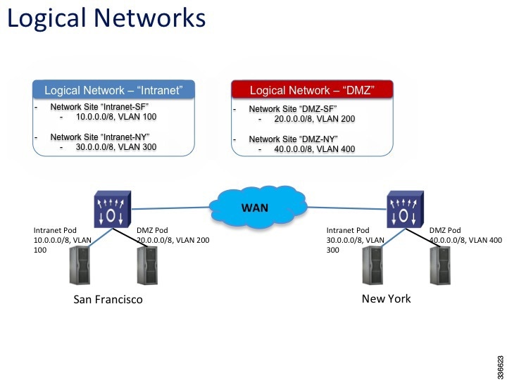
To model the network fabric, the SCVMM administrator creates two logical networks: Intranet and DMZ. The Intranet logical network has two network sites, 10.0.0.0/8 and 30.0.0.0/8 and two VLANs . The DMZ logical network has two network sites, 20.0.0.0/8 and 40.0.0.0/8 and two VLANs. The server administrator deploys the host to the Intranet logical network.
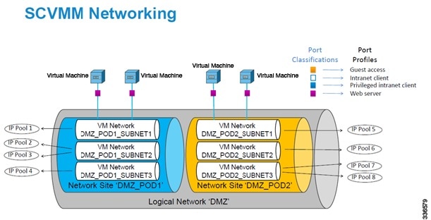
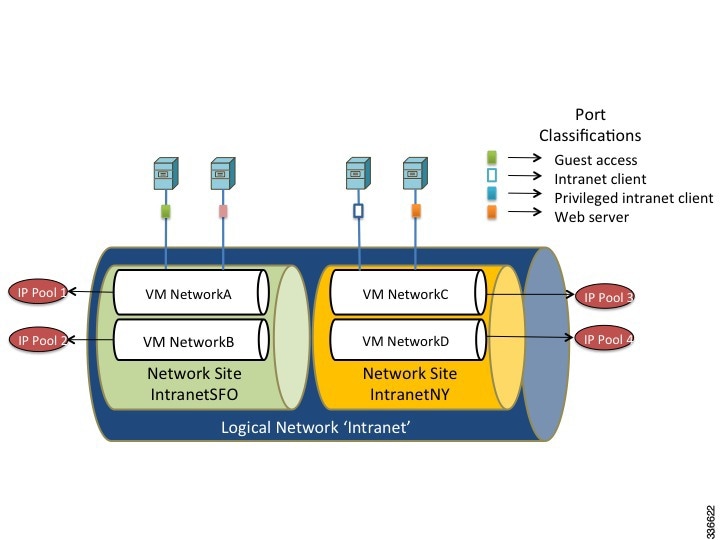
VM Networks
VM networks allow the Microsoft SCVMM administrator to create an isolated virtual Layer 3 network. Each VM network can have one or more VM subnets (virtual Layer 2 domain). The Microsoft SCVMM SP1 supports VLAN-backed and Network Virtualization (NVGRE)-backed VM networks. The Cisco Nexus 1000V allows the network administrators to create the VLAN-backed VM networks only.
Note | The Microsoft SCVMM SP1 allows creating multiple VM subnets under a VM network only when NVGRE is used. A VLAN-backed VM network always contains only one VM subnet. |
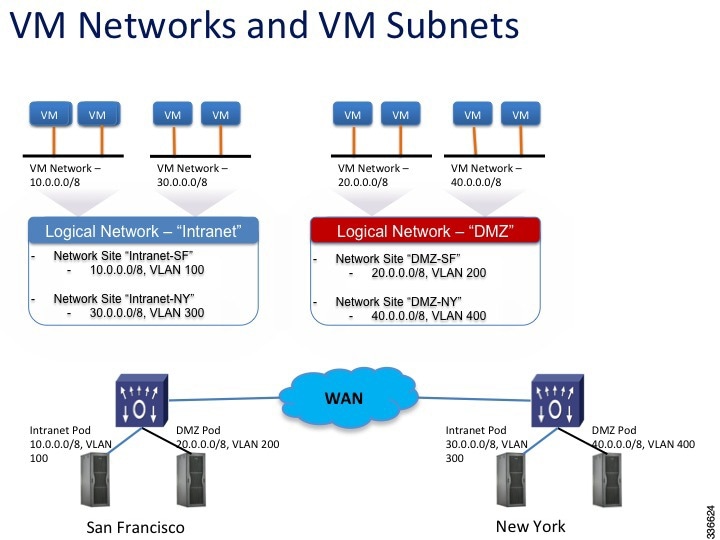
In the example, the San Francisco datacenter has two IP subnets each of which is associated with a VLAN. In San Francisco datacenter, the subnet 10.0.0.0/8 is associated with VLAN 100. The subnet 20.0.0.0/8 is associated with VLAN 200. To deploy the VMs to VLAN 100 and VLAN 200, the network administrator creates two network segments, for example, VMNetworkA and VMNetworkB. After the network administrator creates a network segment VMNetworkA, the Microsoft SCVMM administrator has to create a VM network that uses the network segment, VMNetworkA. This is a prerequisite for the VMs to be deployed to the VLAN/network segment. To deploy the VMs to VLAN 300 and VLAN 400, the network administrator creates two network segments, for example, VMNetworkC and VMNetworkD as illustrated in the following example.
Network Segments
A network segment is associated with a unique broadcast domain. A network segment facilitates the availability of the network resources to a virtual machine. OpenStack controller uses the VM networks and the VM subnets to provide the isolated virtual machine networks. When Cisco Nexus 1000V is used to manage the virtual network, the OpenStack controller creates the VM networks that use an external isolation. An external isolation is provided by creating the network segments on the Cisco Nexus 1000V by the network administrator. The network administrator provides the isolated networks using the VLANs and the private VLANs.
Note | In OpenStack controller, a VLAN is not created to define a bridge domain. Instead, a network segment is created on the VSM. Creating a network segment triggers an auto-creation of VLANs. |
IP Pool Templates
The server administrators can manage the IP addresses for the virtual environment using an IP pool template. You can assign a range of IP addresses to the hosts and to the virtual machines that are running inside the OpenStack environment using the IP pool templates. When you create an IP pool template for a VM network, you can define a range of IP addresses that are used by the VMs that are managed by OpenStack controller.
Note | In an IP pool template, the maximum number of reserved IP addresses is 128. |
The IP pool templates are the address templates that are applied to the network segments.
Port Profiles
A port profile is a collection of the interface-level configuration attributes. The network administrator creates a consistent network policy across the similar VM interfaces by defining the Virtual Ethernet port profiles. The network administrator can also create a port profile for the VM hosts adapters. The profile defines the policy to be applied on the physical Ethernet adapters on the servers.
Policy and Network Separation
In the Cisco Nexus 1000V for OpenStack environment, features and network segments are independently associated with the interfaces. The independent association allows you to assign the same set of features on the interfaces that are spread across multiple dynamically-allocated network segments. With this capability, a network administrator can define the policy profiles and export policy profiles to the OpenStack environment. The OpenStack cloud administrator can allocate the network segments from the network pools dynamically, and associate the virtual machine (VM) interfaces to the policy profile and the allocated network segment. This decoupling provides the flexibility to allocate network segments dynamically while grouping the network features to be applied on the interfaces.
Dynamic Port Profiles
A virtual machine (VM) is deployed to the virtual access layer by choosing the Port Classification, the VM Network, and the VM subnet. When a VM is deployed, a port profile is dynamically created on the Cisco Nexus 1000V for each unique combination of the network segment and policy port profile. All other VMs deployed with the same policy to this network reuse this dynamic port profile. This dynamic port profile is a combination of network isolation and network policy.
Note | The auto-generated profile should neither be modified nor inherited in any other port profiles. |
The port-attach notification carries a port UUID. The VSM looks up the port UUID and retrieves the associated combination of policy port profile and network segment. This combination is represented by a dynamic port profile that is inherited on the interface. If more than one port uses the same combination of policy port profile and the network segment, the dynamic port profile is shared. Dynamic port profiles are auto-created in the VSM as a result of configuration steps executed using SCVMM.
Uplink Port Profile
An uplink port profile is essentially a template in which you define the list of network segment pools that should be associated with any (physical) network adaptors that it is applied to. It also allows you to specify the protocols and the port policy for the uplink adapter using an Ethernet port profile.
Configuring PVLANs
Each network segment is associated with one broadcast domain. In case of PVLAN, each secondary VLAN is considered as one broadcast domain and a network segment is created to represent that. All secondary VLAN network segments for a particular primary VLAN are bundled into one network segment pool and the network segment pool defines which primary VLAN it represents.
For every primary VLAN, a network segment pool is created. The primary VLAN is also represented as a network segment. All secondary network segments and the corresponding primary network segments are bundled into one network segment pool. There can be only one primary VLAN network segment in a given network segment pool. This bundle can also have the normal VLAN network segments.
A network segment identifies whether it represents a community, isolated, or promiscuous port. The secondary VLAN network segments can either be in a community, isolated, or promiscuous mode. When the mode is promiscuous, it can specify which secondary VLANs are allowed. A port attaching to the secondary VLAN network segment becomes a part of a community, or stand isolated, or be in a promiscuous mode and is able to listen on the specified secondary VLANs. A VM port also can be a promiscuous port.
 Feedback