Cisco MDS 9000 Series IP Services Configuration Guide 7.x
Bias-Free Language
The documentation set for this product strives to use bias-free language. For the purposes of this documentation set, bias-free is defined as language that does not imply discrimination based on age, disability, gender, racial identity, ethnic identity, sexual orientation, socioeconomic status, and intersectionality. Exceptions may be present in the documentation due to language that is hardcoded in the user interfaces of the product software, language used based on RFP documentation, or language that is used by a referenced third-party product. Learn more about how Cisco is using Inclusive Language.
- Updated:
- February 14, 2016
Chapter: Configuring IP Storage Services
- Feature Information
- IP Storage Modules
- Supported Hardware
- Configuring Gigabit Ethernet Interfaces for IPv4
- IPS Module Core Dumps
- About VLANs for Gigabit Ethernet
- Interface Subnet Requirements
- Verifying Gigabit Ethernet Connectivity
- Gigabit Ethernet IPv4-ACL Guidelines
- Configuring Gigabit Ethernet High Availability
- Configuring CDP
- Changing Link Speed on IP Storage Interfaces
- Displaying Statistics
- Default Settings for IP Storage Services Parameters
Configuring IP Storage Services
Cisco MDS 9000 Family IP storage (IPS) services extend the reach of Fibre Channel SANs by using open-standard, IP-based technology. The switch connects separated SAN islands using Fibre Channel over IP (FCIP), and it allows IP hosts to access Fibre Channel storage using the iSCSI protocol.

Note![]() FCIP and iSCSI features are specific to the IPS module and are available in Cisco MDS 9200 Switches, Cisco MDS 9500 Directors, and Cisco MDS 9700 Directors.
FCIP and iSCSI features are specific to the IPS module and are available in Cisco MDS 9200 Switches, Cisco MDS 9500 Directors, and Cisco MDS 9700 Directors.
The Cisco MDS 24/10 port SAN Extension Module for MDS 9700, and the 18/4 Multiprotocol Services (MSM-18/4) module also allow you to use Fibre Channel, FCIP, and iSCSI features. The MSM-18/4 module is available for use in any switch in the Cisco MDS 9200 Series or Cisco MDS 9500 Series, and the Cisco MDS 24/10 port SAN Extension Module can be used in any of the Cisco MDS 9700 series switches.
This chapter includes the following sections:
- Feature Information
- IP Storage Modules
- Supported Hardware
- Configuring Gigabit Ethernet Interfaces for IPv4
- IPS Module Core Dumps
- Configuring Gigabit Ethernet High Availability
- Configuring CDP
- Changing Link Speed on IP Storage Interfaces
- Default Settings for IP Storage Services Parameters
Feature Information
This section briefly describes the new and updated features for releases, starting from Cisco MDS NX-OS Release 6.2(13).
|
|
|
|
|---|---|---|
Changing Link Speed on Cisco MDS 24/10 port SAN Extension Module |
This feature enables users to change the link speed on IP Storage interfaces between 1 Gbps and 10 Gbps on the Cisco MDS 24/10 port SAN Extension Module. |
|
Changing Link Speed on Cisco MDS 9250i Multiservice Fabric Switch |
This feature enables users to change the link speed on IP Storage interfaces between 1 Gbps and 10 Gbps on the Cisco MDS 9250i Multiservice Fabric Switch. |
IP Storage Modules
The IP Storage services module (IPS module) and the MSM-18/4 module allow you to use FCIP and iSCSI features. Both modules integrate seamlessly into the Cisco MDS 9000 Family, and support the full range of features available on other switching modules, including VSANs, security, and traffic management.
Gigabit Ethernet ports in these modules can be configured to support the FCIP protocol, the iSCSI protocol, or both protocols simultaneously:
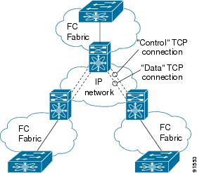
- FCIP—FCIP transports Fibre Channel frames transparently over an IP network between two Cisco MDS 9000 Family switches or other FCIP standards-compliant devices. Figure 6-1 shows how the IPS module is used in different FCIP scenarios.
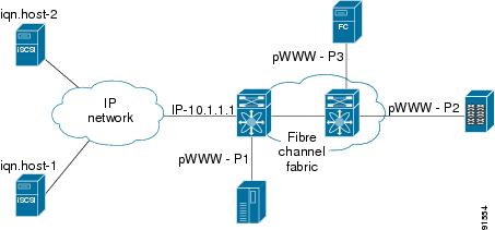
- iSCSI—The IPS module provides IP hosts access to Fibre Channel storage devices. The IP host sends SCSI commands encapsulated in iSCSI protocol data units (PDUs) to a Cisco MDS 9000 Family switch IPS port over a TCP/IP connection. At this point, the commands are routed from an IP network into a Fibre Channel network and forwarded to the intended target. Figure 6-2 depicts the iSCSI scenarios in which the IPS module is used.
Module Status Verification
To verify the status of the module using Fabric Manager, follow these steps:
Step 1![]() Select a switch in the Fabric pane.
Select a switch in the Fabric pane.
Step 2![]() Open the Switches folder and select Hardware in the Physical Attributes pane.
Open the Switches folder and select Hardware in the Physical Attributes pane.
You see the status for all modules in the switch in the Information pane.
After inserting the module, verify the status of the module using the show module command:
IPS Module Upgrade
IPS modules use a rolling upgrade install mechanism where each module in a given switch can only be upgraded in sequence. To guarantee a stable state, each IPS module in a switch requires a 5-minute delay before the next IPS module is upgraded.

Cisco MDS 9250i Switch
The Cisco MDS 9250i switches have 40 Fibre Channel ports (nondisruptive upgrade) and two IP Storage ports (disruptive upgrade). Cisco MDS 9250i switches use a rolling upgrade install mechanism for the two IP Storage ports where each module in a given switch can only be upgraded in sequence.
24/10 port SAN Extension Module
The 24/10 port SAN Extension Modules have 24 Fibre Channel ports (nondisruptive upgrade) and ten IP Storage ports (disruptive upgrade). 24/10 port SAN Extension Modules use a rolling upgrade install mechanism for the ten IP Storage ports where each module in a given switch can only be upgraded in sequence. To guarantee a stable state, each 24/10 port SAN Extension Module in a switch requires a 5-minute delay before the next module is upgraded.
MSM-18/4 Module Upgrade
The MSM-18/4 modules have 18 Fibre Channel ports (nondisruptive upgrade) and four Gigabit Ethernet ports (disruptive upgrade). MSM-18/4 modules use a rolling upgrade install mechanism for the four Gigabit Ethernet ports where each module in a given switch can only be upgraded in sequence. To guarantee a stable state, each MSM-18/4 module in a switch requires a 5-minute delay before the next module is upgraded.
Supported Hardware
You can configure the FCIP and iSCSI features using one or more of the following hardware:
Configuring Gigabit Ethernet Interfaces for IPv4
Both FCIP and iSCSI rely on TCP/IP for network connectivity. On each IPS module, connectivity is provided in the form of Gigabit Ethernet interfaces on Cisco MDS 9500 series switches, and in the form of IP storage ports on Cisco MDS 9250i switches and Cisco MDS 9700 series switches with 24/10 port SAN Extension modules that are appropriately configured. This section covers the steps required to configure IP for subsequent use by FCIP and iSCSI.
A new port mode, called IPS, is defined for Gigabit Ethernet ports on each IPS module. IP storage ports are implicitly set to IPS mode, so it can only be used to perform iSCSI and FCIP storage functions. IP storage ports do not bridge Ethernet frames or route other IP packets.
Each IPS port represents a single virtual Fibre Channel host in the Fibre Channel SAN. All the iSCSI hosts connected to this IPS port are merged and multiplexed through the single Fibre Channel host.
In large scale iSCSI deployments where the Fibre Channel storage subsystems require explicit LUN access control for every host device, use of proxy-initiator mode simplifies the configuration.
Note![]() To configure IPv6 on a Gigabit Ethernet interface, see the Cisco Fabric Manager Security Configuration Guide. For information about configuring FCIP, see Chapter2, “Configuring Fibre Channel over IP” For information about configuring iSCSI, see Chapter4, “Configuring Internet Small Computer Systems Interface”
To configure IPv6 on a Gigabit Ethernet interface, see the Cisco Fabric Manager Security Configuration Guide. For information about configuring FCIP, see Chapter2, “Configuring Fibre Channel over IP” For information about configuring iSCSI, see Chapter4, “Configuring Internet Small Computer Systems Interface”

Tip![]() Gigabit Ethernet ports on any IPS module should not be configured in the same Ethernet broadcast domain as the management Ethernet port—they should be configured in a different broadcast domain, either by using separate standalone hubs or switches or by using separate VLANs.
Gigabit Ethernet ports on any IPS module should not be configured in the same Ethernet broadcast domain as the management Ethernet port—they should be configured in a different broadcast domain, either by using separate standalone hubs or switches or by using separate VLANs.
Basic Gigabit Ethernet Configuration
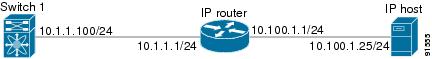
Figure 6-3 shows an example of a basic Gigabit Ethernet IP version 4 (IPv4) configuration.
Figure 6-3 Gigabit Ethernet IPv4 Configuration Example
Note![]() The port on the Ethernet switch to which the Gigabit Ethernet interface is connected should be configured as a host port (also known as access port) instead of a switch port. Spanning tree configuration for that port (on the ethernet switch) should disabled. This helps avoid the delay in the management port coming up due to delay from Ethernet spanning tree processing that the Ethernet switch would run if enabled. For Cisco Ethernet switches, use either the switchport host command in Cisco IOS or the set port host command in Catalyst OS.
The port on the Ethernet switch to which the Gigabit Ethernet interface is connected should be configured as a host port (also known as access port) instead of a switch port. Spanning tree configuration for that port (on the ethernet switch) should disabled. This helps avoid the delay in the management port coming up due to delay from Ethernet spanning tree processing that the Ethernet switch would run if enabled. For Cisco Ethernet switches, use either the switchport host command in Cisco IOS or the set port host command in Catalyst OS.
IPS Module Core Dumps
IPS core dumps are different from the system’s kernel core dumps for other modules. When the IPS module’s operating system (OS) unexpectedly resets, it is useful to obtain a copy of the memory image (called a IPS core dump) to identify the cause of the reset. Under that condition, the IPS module sends the core dump to the supervisor module for storage. Cisco MDS switches have two levels of IPS core dumps:
- Partial core dumps (default)—Each partial core dump consists of four parts (four files). All four files are saved in the active supervisor module.
In Cisco MDS 9700 Series Switches with 24/10 port SAN Extension Modules, each partial core dump consists of five parts (five files). All five files are saved in the active supervisor module.
Use the show cores command to list these files.
- Full core dumps—Each full core dump of Cisco MDS 9250i Switches and SSN-16 modules consists of 64 parts (64 files), and each full core dump of Cisco MDS 9700 Series Switches with 24/10 port SAN Extension Modules consists of 67 parts (67 files). The IPS core dump for MSM-18/4 modules consists of 32 parts. This dump cannot be saved on the supervisor module because of its large space requirement. They are copied directly to an external TFTP server.
Use the system cores tftp: command to configure an external TFTP server to copy the IPS core dump (and other core dumps).
To configure IPS core dumps on the IPS module, follow these steps:
|
|
|
|
|---|---|---|
Configures a dump of the full core generation for all IPS modules in the switch. |
||
Configures a dump of the partial core (default) generation for the IPS module in slot 9. |
To configure the Gigabit Ethernet interface for the scenario in Figure 6-3, follow these steps:
Step 1![]() From Fabric Manager, choose Switches > Interfaces > Gigabit Ethernet in the Physical Attributes pane. You see the Gigabit Ethernet configuration in the Information pane.
From Fabric Manager, choose Switches > Interfaces > Gigabit Ethernet in the Physical Attributes pane. You see the Gigabit Ethernet configuration in the Information pane.
From Device Manager, right-click the Gigabit Ethernet port that you want to configure and choose Configure.... You see the Gigabit Ethernet configuration dialog box.
Step 2![]() Click the General tab in Fabric Manager, or click the GigE tab in Device Manager to display the general configuration options for the interface.
Click the General tab in Fabric Manager, or click the GigE tab in Device Manager to display the general configuration options for the interface.
Step 3![]() Set the description and MTU value for the interface. The valid value for the MTU field can be a number in the range from 576 to 9000.
Set the description and MTU value for the interface. The valid value for the MTU field can be a number in the range from 576 to 9000.
Step 4![]() Set Admin up or down and check the CDP check box if you want this interface to participate in CDP.
Set Admin up or down and check the CDP check box if you want this interface to participate in CDP.
Step 5![]() Set IpAddress/Mask with the IP address and subnet mask for this interface.
Set IpAddress/Mask with the IP address and subnet mask for this interface.
Step 6![]() From Fabric Manager, click the Apply Changes icon to save these changes, or click the Undo Changes icon to discard changes.
From Fabric Manager, click the Apply Changes icon to save these changes, or click the Undo Changes icon to discard changes.
From Device Manager, click Apply to save these changes, or click Close to discard changes and close the Gigabit Ethernet configuration dialog box.
Configuring Interface Descriptions
See the Cisco Fabric Manager Interfaces Configuration Guide for details on configuring the switch port description for any interface.
Configuring Beacon Mode
See the Cisco Fabric Manager Interfaces Configuration Guide for details on configuring the beacon mode for any interface.
Configuring Autonegotiation
By default, autonegotiation is enabled all Gigabit Ethernet interface. You can enable or disable autonegotiation for a specified Gigabit Ethernet interface. When autonegotiation is enabled, the port automatically detects the speed or pause method, and duplex of incoming signals based on the link partner. You can also detect link up conditions using the autonegotiation feature.
Configuring the MTU Frame Size
You can configure the interfaces on a switch to transfer large (or jumbo) frames on a port. The default IP maximum transmission unit (MTU) frame size is 1500 bytes for all Ethernet ports. By configuring jumbo frames on a port, the MTU size can be increased up to 9000 bytes.
Note![]() The minimum MTU size is 576 bytes.
The minimum MTU size is 576 bytes.
Tip![]() MTU changes are disruptive, all FCIP links and iSCSI sessions flap when the software detects a change in the MTU size.
MTU changes are disruptive, all FCIP links and iSCSI sessions flap when the software detects a change in the MTU size.
Configuring Promiscuous Mode
You can enable or disable promiscuous mode on a specific Gigabit Ethernet interface. By enabling the promiscuous mode, the Gigabit Ethernet interface receives all the packets and the software then filters and discards the packets that are not destined for that Gigabit Ethernet interface.
About VLANs for Gigabit Ethernet
Virtual LANs (VLANs) create multiple virtual Layer 2 networks over a physical LAN network. VLANs provide traffic isolation, security, and broadcast control.
Gigabit Ethernet ports automatically recognize Ethernet frames with IEEE 802.1Q VLAN encapsulation. If you need to have traffic from multiple VLANs terminated on one Gigabit Ethernet port, configure subinterfaces—one for each VLAN.
If the IPS module or MPS-14/2 module is connected to a Cisco Ethernet switch, and you need to have traffic from multiple VLANs coming to one IPS port, verify the following requirements on the Ethernet switch:
Use the VLAN ID as a subscription to the Gigabit Ethernet interface name to create the subinterface name: slot-number / port-numberVLAN-ID.
Interface Subnet Requirements
Gigabit Ethernet interfaces (major), subinterfaces (VLAN ID), and management interfaces (mgmt 0) can be configured in the same or different subnet depending on the configuration (see Table 6-2 ).
Note![]() The configuration requirements in Table 6-2 also apply to Ethernet PortChannels.
The configuration requirements in Table 6-2 also apply to Ethernet PortChannels.
Verifying Gigabit Ethernet Connectivity
Once the Gigabit Ethernet interfaces are connected with valid IP addresses, verify the interface connectivity on each switch. Ping the IP host using the IP address of the host to verify that the static IP route is configured correctly.
Note![]() If the connection fails, verify the following, and ping the IP host again:
If the connection fails, verify the following, and ping the IP host again:
- The IP address for the destination (IP host) is correctly configured.
- The host is active (powered on).
- The IP route is configured correctly.
- The IP host has a route to get to the Gigabit Ethernet interface subnet.
- The Gigabit Ethernet interface is in the up state.
Gigabit Ethernet IPv4-ACL Guidelines
Tip![]() If IPv4-ACLs are already configured in a Gigabit Ethernet interface, you cannot add this interface to an Ethernet PortChannel group.
If IPv4-ACLs are already configured in a Gigabit Ethernet interface, you cannot add this interface to an Ethernet PortChannel group.
Follow these guidelines when configuring IPv4-ACLs for Gigabit Ethernet interfaces:
Note![]() Other protocols such as User Datagram Protocol (UDP) and HTTP are not supported in Gigabit Ethernet interfaces. Applying an ACL that contains rules for these protocols to a Gigabit Ethernet interface is allowed but those rules have no effect.
Other protocols such as User Datagram Protocol (UDP) and HTTP are not supported in Gigabit Ethernet interfaces. Applying an ACL that contains rules for these protocols to a Gigabit Ethernet interface is allowed but those rules have no effect.
- Apply IPv4-ACLs to the interface before you enable an interface. This ensures that the filters are in place before traffic starts flowing.
- Be aware of the following conditions:
–![]() If you use the log-deny option, a maximum of 50 messages are logged per second.
If you use the log-deny option, a maximum of 50 messages are logged per second.
–![]() The established, precedence, and fragments options are ignored when you apply IPv4-ACLs (containing these options) to Gigabit Ethernet interfaces.
The established, precedence, and fragments options are ignored when you apply IPv4-ACLs (containing these options) to Gigabit Ethernet interfaces.
–![]() If an IPv4-ACL rule applies to a preexisting TCP connection, that rule is ignored. For example if there is an existing TCP connection between A and B, and an IPv4-ACL specifies dropping all packets whose source is A and destination is B is subsequently applied, it will have no effect.
If an IPv4-ACL rule applies to a preexisting TCP connection, that rule is ignored. For example if there is an existing TCP connection between A and B, and an IPv4-ACL specifies dropping all packets whose source is A and destination is B is subsequently applied, it will have no effect.
Configuring Gigabit Ethernet High Availability
Virtual Router Redundancy Protocol (VRRP) and Ethernet PortChannels are two Gigabit Ethernet features that provide high availability for iSCSI and FCIP services.
VRRP for iSCSI and FCIP Services
VRRP provides a redundant alternate path to the Gigabit Ethernet port for iSCSI and FCIP services. VRRP provides IP address failover protection to an alternate Gigabit Ethernet interface so the IP address is always available (see Figure 6-4).
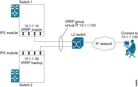
In Figure 6-4, all members of the VRRP group must be IP storage Gigabit Ethernet ports. VRRP group members can be one or more of the following interfaces:
- One or more interfaces in the same IPS module or MSM-18/4 module
- Interfaces across IPS modules or MSM-18/4 modules in one switch
- Interfaces across IPS modules or MSM-18/4 modules in different switches
- Gigabit Ethernet subinterfaces
- Ethernet PortChannels and PortChannel subinterfaces
Note![]() You can configure no more than seven VRRP groups, both IPv4 and IPv6, on a Gigabit Ethernet interface, including the main interface and all subinterfaces.
You can configure no more than seven VRRP groups, both IPv4 and IPv6, on a Gigabit Ethernet interface, including the main interface and all subinterfaces.
Configuring VRRP for Gigabit Ethernet Interfaces
To configure VRRP for Gigabit Ethernet interfaces using IPv4, follow these steps:
To configure VRRP for Gigabit Ethernet interfaces using IPv6, follow these steps:
Note![]() If you configure secondary VRRP IPv6 addresses on an IPFC VSAN interface, before a downgrading to a release prior to Cisco Release 3.0(1), you must remove the secondary VRRP IPv6 addresses. This is required only when you configure IPv6 addresses.
If you configure secondary VRRP IPv6 addresses on an IPFC VSAN interface, before a downgrading to a release prior to Cisco Release 3.0(1), you must remove the secondary VRRP IPv6 addresses. This is required only when you configure IPv6 addresses.
Note![]() The VRRP preempt option is not supported on IPS Gigabit Ethernet interfaces. However, if the virtual IPv4 IP address is also the IPv4 IP address for the interface, then preemption is implicitly applied.
The VRRP preempt option is not supported on IPS Gigabit Ethernet interfaces. However, if the virtual IPv4 IP address is also the IPv4 IP address for the interface, then preemption is implicitly applied.
Note![]() If you configure secondary VRRP IPv6 addresses on an IPFC VSAN interface, before a downgrading to a release prior to Cisco Release 3.0(1), you must remove the secondary VRRP IPv6 addresses. This is required only when you configure IPv6 addresses.
If you configure secondary VRRP IPv6 addresses on an IPFC VSAN interface, before a downgrading to a release prior to Cisco Release 3.0(1), you must remove the secondary VRRP IPv6 addresses. This is required only when you configure IPv6 addresses.
Configuring CDP
The Cisco Discovery Protocol (CDP) is supported on the management Ethernet interface on the supervisor module and the Gigabit Ethernet interfaces on the IPS module or MSM-18/4 module.
See the Cisco MDS 9000 Family NX-OS Fundamentals Configuration Guide.
Changing Link Speed on IP Storage Interfaces
Changing Link Speed on Cisco MDS 9250i Multiservice Fabric Switch
The Cisco MDS 9250i Multiservice Fabric Switch has two IP storage interfaces that support 1 Gbps and 10 Gbps link speeds. By default, IP storage interfaces are configured at 10 Gbps link speed.
Note![]() Switching between different link speeds is supported on Cisco 10 Gbps IP storage platforms starting from Cisco MDS NX-OS Release 6.2(13). An ISSD to a release earlier than Cisco MDS NX-OS Release 6.2(13) when any of the IP storage ports are configured at 1 Gbps, is disallowed. Reconfigure such ports back to the default link speed of 10 Gbps before attempting such a downgrade.
Switching between different link speeds is supported on Cisco 10 Gbps IP storage platforms starting from Cisco MDS NX-OS Release 6.2(13). An ISSD to a release earlier than Cisco MDS NX-OS Release 6.2(13) when any of the IP storage ports are configured at 1 Gbps, is disallowed. Reconfigure such ports back to the default link speed of 10 Gbps before attempting such a downgrade.
To configure 1 Gbps link speed on an IP storage interface, follow these steps:
|
|
|
|
|---|---|---|
|
|
||
Administratively disables the interface and stops traffic through the interface. |
||
switch(config-if)# switchport speed 10001 |
Sets the link speed of the interface and all subinterfaces to 1000 Mbps (1 Gbps). This command causes all IP storage ports on the selected FCIP engine to be reset. This may cause traffic disruption for up to 5 minutes. By default, n is selected. Press Enter to abort the command. Enter y and press Enter to continue. |
|
Exits IPStorage interface configuration mode and returns to privileged EXEC mode. |
||
To configure 10 Gbps link speed on an IP storage interface, follow these steps:
|
|
|
|
|---|---|---|
|
|
||
Administratively disables the interface and stops traffic through the interface. |
||
switch(config-if)# switchport speed 100003 |
Sets the link speed of the interface and all subinterfaces to 10000 Mbps (10 Gbps). This command causes all IP storage ports on the selected FCIP engine to be reset. This may cause traffic disruption for up to 5 minutes. By default, n is selected. Press Enter to abort the command. Enter y and press Enter to continue. |
|
Exits IPStorage interface configuration mode and returns to privileged EXEC mode. |
||
If there is a mismatch between the configured link speed and the small form-factor pluggable (SFP) speed capabilities, the port goes into an Error Disabled state and a corresponding syslog message is logged. In such a scenario, either the configured link speed or the SFP should be changed. If the link speed is changed, even if the port is already enabled, the shutdown and no shutdown commands must be explicitly issued for the change to be applied.
For more information about supported 1 Gbps SFPs for a Cisco MDS 9250i Multiservice Fabric Switch, see the Cisco MDS 9000 Family Pluggable Transceivers Data Sheet.
For information about configuring FCIP tunnels with IP storage interfaces at 1 Gbps speed, see the Configuring FCIP chapter.
Changing Link Speed on Cisco MDS 24/10 port SAN Extension Module
To configure 1 Gbps link speed on an IP storage interface, follow these steps:
To configure 10 Gbps link speed on an IP storage interface, follow these steps:
Displaying Statistics
This section provides examples to verify Gigabit Ethernet and TCP/IP statistics on the IP storage ports.
Displaying Gigabit Ethernet Interface Statistics
Use the show interface gigabitethernet command on each switch to verify that the interfaces are up and functioning as desired. See Example 6-1 and Example 6-2.
Example 6-1 Displaying the Gigabit Ethernet Interface
Example 6-2 Displaying the Gigabit Ethernet Subinterface
Example 6-3 Displaying the IP Storage Interface
Note![]() In Cisco MDS NX-OS Release 7.3(0)DY(1), 40GE IP Storage interfaces are not supported.
In Cisco MDS NX-OS Release 7.3(0)DY(1), 40GE IP Storage interfaces are not supported.
Displaying Ethernet MAC Statistics
The show ips stats mac interface gigabitethernet command takes the main Gigabit Ethernet interface as a parameter and returns Ethernet statistics for that interface. See Example 6-4.
Note![]() Use the physical interface, not the subinterface, to display Ethernet MAC statistics.
Use the physical interface, not the subinterface, to display Ethernet MAC statistics.
Example 6-4 Displaying Ethernet MAC Statistics
Displaying TCP Statistics
Use the show ips stats tcp interface gigabitethernet to display and verify TCP statistics. This command takes the main Ethernet interface as a parameter, and shows TCP stats along with the connection list and TCP state. The detail option shows all information maintained by the interface. See Example 6-5 and Example 6-6.
Example 6-5 Displaying TCP Statistics
Example 6-6 Displaying Detailed TCP Statistics
Use the show ips stats icmp interface gigabitethernet to display and verify IP statistics. This command takes the main Ethernet interface as a parameter and returns the ICMP statistics for that interface. See Example 6-7.
Example 6-7 Displaying ICMP Statistics
Displaying IP Storage Ports Speed
Use the show ips status command to verify the programmed speed of an IP storage port.
Example 6-8 Displays IP Storage Port Speed
Default Settings for IP Storage Services Parameters
Table 6-3 lists the default settings for IP storage services parameters.
|
|
|
|---|---|
 Feedback