- New and Changed Information
- Preface
- Overview
- Using the CFS Infrastructure
- Configuring System Message Logging
- Configuring Callhome
- Scheduling Maintenance Jobs
- Monitoring System Processes and Log
- Configuring Embeddded Event Manager
- Configuring RMON
- Configuring Generic Online Diagnostics
- Configuring SNMP
- Configuring Domain Parameters
- Monitoring Network Traffic Using SPAN
- Configuring Fabric Configuration Servers
- Configuring Port Pacer
Cisco MDS 9000 Family NX-OS System Management Configuration Guide
Bias-Free Language
The documentation set for this product strives to use bias-free language. For the purposes of this documentation set, bias-free is defined as language that does not imply discrimination based on age, disability, gender, racial identity, ethnic identity, sexual orientation, socioeconomic status, and intersectionality. Exceptions may be present in the documentation due to language that is hardcoded in the user interfaces of the product software, language used based on RFP documentation, or language that is used by a referenced third-party product. Learn more about how Cisco is using Inclusive Language.
- Updated:
- July 15, 2014
Chapter: Configuring Domain Parameters
- Information About Fibre Channel Domains
Configuring Domain Parameters
The Fibre Channel domain (fcdomain) feature performs principal switch selection, domain ID distribution, FC ID allocation, and fabric reconfiguration functions as described in the FC-SW-2 standards.
Information About Fibre Channel Domains
The Fibre Channel domain (fcdomain) feature performs principal switch selection, domain ID distribution, FC ID allocation, and fabric reconfiguration functions as described in the FC-SW-2 standards. The domains are configured on a per VSAN basis. If you do not configure a domain ID, the local switch uses a random ID.
This section describes each fcdomain phase:
- Principal switch selection—This phase guarantees the selection of a unique principal switch across the fabric.
- Domain ID distribution—This phase guarantees each switch in the fabric obtains a unique domain ID.
- FC ID allocation—This phase guarantees a unique FC ID assignment to each device attached to the corresponding switch in the fabric.
- Fabric reconfiguration—This phase guarantees a resynchronization of all switches in the fabric to ensure they simultaneously restart a new principal switch selection phase.

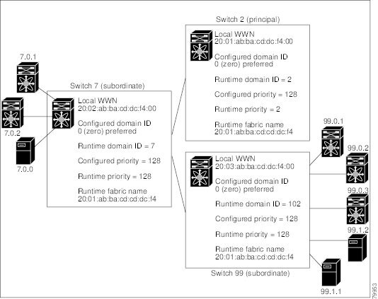
Figure 11-1 shows a sample fcdomain configuration.
Figure 11-1 Sample fcdomain Configuration
This section includes the following topics:
- Domain Restart
- Domain Manager All Optimization
- Domain Manager Fast Restart
- Domain Manager Scale Restart
- Domain Manager Selective Restart
- Switch Priority
- fcdomain Initiation
- Incoming RCFs
- Autoreconfiguring Merged Fabrics
- Domain IDs
- Locking the Fabric
- Committing Changes
- Clearing a Fabric Lock
- FC IDs
Domain Restart
Fibre Channel domains can be started disruptively or nondisruptively. If you perform a disruptive restart, reconfigure fabric (RCF) frames are sent to other switches in the fabric and data traffic is disrupted on all the switches in the VSAN (including remotely segmented ISLs). If you perform a nondisruptive restart, build fabric (BF) frames are sent to other switches in the fabric and data traffic is disrupted only on the switch.
If you are attempting to resolve a domain ID conflict, you must manually assign domain IDs. A disruptive restart is required to apply most configuration changes, including manually assigned domain IDs. Nondisruptive domain restarts are acceptable only when changing a preferred domain ID into a static one (and the actual domain ID remains the same).

Note![]() It is not recommended to use disruptive restart followed by VSAN suspend / no-suspend, since it is used only for recovery purpose when normal restart does not solve the problem.
It is not recommended to use disruptive restart followed by VSAN suspend / no-suspend, since it is used only for recovery purpose when normal restart does not solve the problem.
Note![]() A static domain is specifically configured by the user and may be different from the runtime domain. If the domain IDs are different, the runtime domain ID changes to take on the static domain ID after the next restart, either disruptive or nondisruptive.
A static domain is specifically configured by the user and may be different from the runtime domain. If the domain IDs are different, the runtime domain ID changes to take on the static domain ID after the next restart, either disruptive or nondisruptive.

Tip![]() If a VSAN is in interop mode, you cannot restart the fcdomain for that VSAN disruptively.
If a VSAN is in interop mode, you cannot restart the fcdomain for that VSAN disruptively.
You can apply most of the configurations to their corresponding runtime values. Each of the following sections provide further details on how the fcdomain parameters are applied to the runtime values.
The fcdomain restart command applies your changes to the runtime settings. Use the disruptive option to apply most of the configurations to their corresponding runtime values, including preferred domain IDs (see the “Domain IDs” section).
Domain Manager All Optimization
Domain Manager All Optimization feature can be used to enable or disable all of the optimization modes.
Note![]() You cannot enable all the optimizations such as Selective Restart, Fast Restart, and Scale Restart in VSANs where Interop mode is enabled (non-native modes). Also you cannot move a VSAN where the optimizations are enabled into Interop mode 1 to 4.
You cannot enable all the optimizations such as Selective Restart, Fast Restart, and Scale Restart in VSANs where Interop mode is enabled (non-native modes). Also you cannot move a VSAN where the optimizations are enabled into Interop mode 1 to 4.
Domain Manager Fast Restart
As of Cisco MDS SAN-OS Release 3.0(2), when a principal link fails, the domain manager must select a new principal link. By default, the domain manager starts a build fabric phase, followed by a principal switch selection phase. Both of these phases involve all the switches in the VSAN and together take at least 15 seconds to complete. To reduce the time required for the domain manager to select a new principal link, you can enable the domain manager fast restart feature.
When fast restart is enabled and a backup link is available, the domain manager needs only a few milliseconds to select a new principal link to replace the one that failed. Also, the reconfiguration required to select the new principal link only affects the two switches that are directly attached to the failed link, not the entire VSAN. When a backup link is not available, the domain manager reverts to the default behavior and starts a build fabric phase, followed by a principal switch selection phase. We recommend using fast restart on most fabrics, especially those with a large number of logical ports (3200 or more), where a logical port is an instance of a physical port in a VSAN.
Domain Manager Scale Restart
During fabric reconfiguration, as and when principal switch assigns a domain ID to a switch (including itself), it transmits an Exchange Fabric Parameter (EFP) request. This request basically carries domain list information of the fabric. So whenever domain list grows there will be a Exchange Fabric Parameter flooded to the fabric. With this feature optimization enabled, a single consolidated Exchange Fabric Parameter request will be flooded by the principal switch once the domain identifier allocation phase is completed. This feature optimization cannot be supported in interop mode.
Scale Restart will be enabled by default in all native VSANs. It will not be enabled in interop VSANs.
Domain Manager Selective Restart
In the Fibre Channel protocol, fabric reconfiguration starts with build fabric frame flooding, which indicates to all the switches in the fabric that the fabric is changing. This process is followed by principal switch selection and domain ID allocation phases. During the build fabric flooding phase, build fabric frames are flooded on all the links. A switch may have more than one link to a peer switch. In such cases, the build fabric frame can be sent to only one of the links to the peer switch. This situation reduces the number of build fabric frames that are to be exchanged during the build fabric phase of fabric reconfiguration. Enabling this feature optimization, sends the build frame to only one of the peer switch links which benefits scaling.
Switch Priority
Any new switch can become the principal switch when it joins a stable fabric. During the principal switch selection phase, the switch with the highest priority becomes the principal switch. If two switches have the same configured priority, the switch with the lower WWN becomes the principal switch.
The priority configuration is applied to runtime when the fcdomain is restarted (see the “Domain Restart” section). This configuration is applicable to both disruptive and nondisruptive restarts.
fcdomain Initiation
By default, the fcdomain feature is enabled on each switch. If you disable the fcdomain feature in a switch, that switch can no longer participate with other switches in the fabric. The fcdomain configuration is applied to runtime through a disruptive restart.
Incoming RCFs
You can configure the rcf-reject option on a per-interface, per-VSAN basis. By default, the rcf-reject option is disabled (that is, RCF request frames are not automatically rejected).
The rcf-reject option takes effect immediately. No fcdomain restart is required.
Autoreconfiguring Merged Fabrics
By default, the autoreconfigure option is disabled. When you join two switches belonging to two different stable fabrics that have overlapping domains, the following cases apply:
- If the autoreconfigure option is enabled on both switches, a disruptive reconfiguration phase is started.
- If the autoreconfigure option is disabled on either or both switches, the links between the two switches become isolated.
- RCF is expected only when auto-reconfigure is enabled in entire fabric.
The autoreconfigure option takes immediate effect at runtime. You do not need to restart the fcdomain. If a domain is currently isolated due to domain overlap, and you later enable the autoreconfigure option on both switches, the fabric continues to be isolated. If you enabled the autoreconfigure option on both switches before connecting the fabric, a disruptive reconfiguration (RCF) will occur. A disruptive reconfiguration may affect data traffic. You can nondisruptively reconfigure the fcdomain by changing the configured domains on the overlapping links and eliminating the domain overlap.
Domain IDs
Domain IDs uniquely identify a switch in a VSAN. A switch may have different domain IDs in different VSANs. The domain ID is part of the overall FC ID.
The configured domain ID can be preferred or static. By default, the configured domain ID is 0 (zero) and the configured type is preferred.
Note![]() The 0 (zero) value can be configured only if you use the preferred option.
The 0 (zero) value can be configured only if you use the preferred option.
If you do not configure a domain ID, the local switch sends a random ID in its request. We recommend that you use static domain IDs.
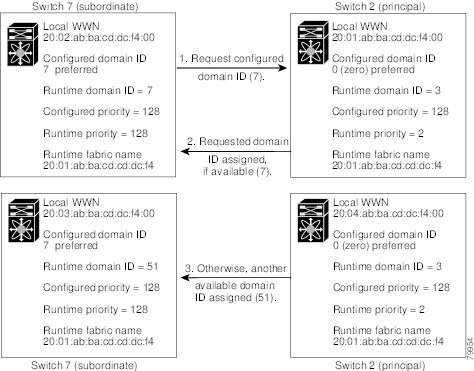
When a subordinate switch requests a domain, the following process takes place (see Figure 11-2):
1.![]() The local switch sends a configured domain ID request to the principal switch.
The local switch sends a configured domain ID request to the principal switch.
2.![]() The principal switch assigns the requested domain ID if available. Otherwise, it assigns another available domain ID.
The principal switch assigns the requested domain ID if available. Otherwise, it assigns another available domain ID.
Figure 11-2 Configuration Process Using the preferred Option
The behavior for a subordinate switch changes based on three factors:
- The allowed domain ID lists.
- The configured domain ID.
- The domain ID that the principal switch has assigned to the requesting switch.
In specific situations, the changes are as follows:
- When the received domain ID is not within the allowed list, the requested domain ID becomes the runtime domain ID and all interfaces on that VSAN are isolated.
- When the assigned and requested domain IDs are the same, the preferred and static options are not relevant, and the assigned domain ID becomes the runtime domain ID.
- When the assigned and requested domain IDs are different, the following cases apply:
–![]() If the configured type is static, the assigned domain ID is discarded, all local interfaces are isolated, and the local switch assigns itself the configured domain ID, which becomes the runtime domain ID.
If the configured type is static, the assigned domain ID is discarded, all local interfaces are isolated, and the local switch assigns itself the configured domain ID, which becomes the runtime domain ID.
–![]() If the configured type is preferred, the local switch accepts the domain ID assigned by the principal switch and the assigned domain ID becomes the runtime domain ID.
If the configured type is preferred, the local switch accepts the domain ID assigned by the principal switch and the assigned domain ID becomes the runtime domain ID.
If you change the configured domain ID, the change is only accepted if the new domain ID is included in all the allowed domain ID lists currently configured in the VSAN. Alternatively, you can also configure zero-preferred domain ID.
Tip![]() When the FICON feature is enabled in a given VSAN, the domain ID for that VSAN remains in the static state. You can change the static ID value but you cannot change it to the preferred option.
When the FICON feature is enabled in a given VSAN, the domain ID for that VSAN remains in the static state. You can change the static ID value but you cannot change it to the preferred option.
Note![]() In an IVR without NAT configuration, if one VSAN in the IVR topology is configured with static domain IDs, then the other VSANs (edge or transit) in the topology should also be configured with static domain IDs.
In an IVR without NAT configuration, if one VSAN in the IVR topology is configured with static domain IDs, then the other VSANs (edge or transit) in the topology should also be configured with static domain IDs.
In an IVR NAT configuration, if one VSAN in the IVR topology is configured with static domain IDs, then the IVR domains that can be exported to that VSAN must also be assigned static domains.
Note![]() If you have configured an allowed domain ID list, the domain IDs that you add must be in that range for the VSAN. See the “Configuring Allowed Domain ID Lists” section.
If you have configured an allowed domain ID list, the domain IDs that you add must be in that range for the VSAN. See the “Configuring Allowed Domain ID Lists” section.
Specifying Static or Preferred Domain IDs
When you assign a static domain ID type, you are requesting a particular domain ID. If the switch does not get the requested address, it will isolate itself from the fabric. When you specify a preferred domain ID, you are also requesting a particular domain ID; however, if the requested domain ID is unavailable, then the switch will accept another domain ID.
While the static option can be applied at runtime after a disruptive or nondisruptive restart, the preferred option is applied at runtime only after a disruptive restart (see the “Domain Restart” section).
Allowed Domain ID Lists
By default, the valid range for an assigned domain ID list is from 1 to 239. You can specify a list of ranges to be in the allowed domain ID list and separate each range with a comma. The principal switch assigns domain IDs that are available in the locally configured allowed domain list.
Use allowed domain ID lists to design your VSANs with non-overlapping domain IDs. This helps you in the future if you need to implement IVR without the NAT feature.
CFS Distribution of Allowed Domain ID Lists
You can enable the distribution of the allowed domain ID lists configuration information to all Cisco MDS switches in the fabric using the Cisco Fabric Services (CFS) infrastructure. This feature allows you to synchronize the configuration across the fabric from the console of a single MDS switch. Since the same configuration is distributed to the entire VSAN, you avoid possible misconfiguration and the likelihood that two switches in the same VSAN have configured incompatible allowed domains.
Use CFS to distribute the allowed domain ID list to ensure consistency in the allowed domain ID lists on all switches in the VSAN.
Note![]() We recommend configuring the allow domain ID list and committing it on the principle switch.
We recommend configuring the allow domain ID list and committing it on the principle switch.
For more information about CFS, see Chapter 2, “Using the CFS Infrastructure”.
Contiguous Domain ID Assignments
By default, the contiguous domain assignment is disabled. When a subordinate switch requests the principal switch for two or more domains and the domains are not contiguous, the following cases apply:
- If the contiguous domain assignment is enabled in the principal switch, the principal switch locates contiguous domains and assigns them to the subordinate switches. If contiguous domains are not available, the NX-OS software rejects this request.
- If the contiguous domain assignment is disabled in the principal switch, the principal switch assigns the available domains to the subordinate switch.
Locking the Fabric
The first action that modifies the existing configuration creates the pending configuration and locks the feature in the fabric. Once you lock the fabric, the following conditions apply:
- No other user can make any configuration changes to this feature.
- A pending configuration is created by copying the active configuration. Modifications from this point on are made to the pending configuration and remain there until you commit the changes to the active configuration (and other switches in the fabric) or discard them.
Committing Changes
To apply the pending domain configuration changes to other MDS switches in the VSAN, you must commit the changes. The pending configuration changes are distributed and, on a successful commit, the configuration changes are applied to the active configuration in the MDS switches throughout the VSAN and the fabric lock is released.
Clearing a Fabric Lock
If you have performed a domain configuration task and have not released the lock by either committing or discarding the changes, an administrator can release the lock from any switch in the fabric. If the administrator performs this task, your pending changes are discarded and the fabric lock is released.
The pending changes are only available in the volatile directory and are discarded if the switch is restarted.
FC IDs
When an N or NL port logs into a Cisco MDS 9000 Family switch, it is assigned an FC ID. By default, the persistent FC ID feature is enabled. If this feature is disabled, the following consequences apply:
- An N or NL port logs into a Cisco MDS 9000 Family switch. The WWN of the requesting N or NL port and the assigned FC ID are retained and stored in a volatile cache. The contents of this volatile cache are not saved across reboots.
- The switch is designed to preserve the binding FC ID to the WWN on a best-effort basis. For example, if one N port disconnects from the switch and its FC ID is requested by another device, this request is granted and the WWN with the initial FC ID association is released.
- The volatile cache stores up to 4000 entries of WWN to FC ID binding. If this cache is full, a new (more recent) entry overwrites the oldest entry in the cache. In this case, the corresponding WWN to FC ID association for the oldest entry is lost.
- The switch connection behavior differs between N ports and NL ports:
–![]() N ports receive the same FC IDs if disconnected and reconnected to any port within the same switch (as long as it belongs to the same VSAN).
N ports receive the same FC IDs if disconnected and reconnected to any port within the same switch (as long as it belongs to the same VSAN).
–![]() NL ports receive the same FC IDs only if connected back to the same port on the switch to which they were originally connected.
NL ports receive the same FC IDs only if connected back to the same port on the switch to which they were originally connected.
Persistent FC IDs
When persistent FC IDs are enabled, the following consequences apply:
Persistent FC ID Configuration
When the persistent FC ID feature is enabled, you can enter the persistent FC ID submode and add static or dynamic entries in the FC ID database. By default, all added entries are static. Persistent FC IDs are configured on a per-VSAN basis. Follow these requirements to manually configure a persistent FC ID:
- Ensure that the persistent FC ID feature is enabled in the required VSAN.
- Ensure that the required VSAN is an active VSAN—persistent FC IDs can only be configured on active VSANs.
- Verify that the domain part of the FC ID is the same as the runtime domain ID in the required VSAN. If the software detects a domain mismatch, the command is rejected.
- Verify that the port field of the FC ID is 0 (zero) when configuring an area.
Note![]() FICON uses a different scheme for allocating FC IDs based in the front panel port number. This scheme takes precedence over FC ID persistence in FICON VSANs.
FICON uses a different scheme for allocating FC IDs based in the front panel port number. This scheme takes precedence over FC ID persistence in FICON VSANs.
About Unique Area FC IDs for HBAs
Note![]() Read this section only if the HBA port and the storage port are connected to the same switch.
Read this section only if the HBA port and the storage port are connected to the same switch.
Some HBA ports require a different area ID than storage ports when they are both connected to the same switch. For example, if the storage port FC ID is 0x6f7704, the area for this port is 77. In this case, the HBA port’s area can be anything other than 77. The HBA port’s FC ID must be manually configured to be different from the storage port’s FC ID.
Switches in the Cisco MDS 9000 Family facilitate this requirement with the FC ID persistence feature. You can use this feature to preassign an FC ID with a different area to either the storage port or the HBA port.
Persistent FC ID Selective Purging
Persistent FC IDs can be purged selectively. Static entries and FC IDs currently in use cannot be deleted. Table 11-1 identifies the FC ID entries that are deleted or retained when persistent FC IDs are purged.
|
|
|
|
|---|---|---|
Guidelines and Limitations
- When you change the configuration, be sure to save the running configuration. The next time you reboot the switch, the saved configuration is used. If you do not save the configuration, the previously saved startup configuration is used.
- Domain IDs and VSAN values used in all procedures are only provided as examples. Be sure to use IDs and values that apply to your configuration.
Default Settings
Table 11-2 lists the default settings for all fcdomain parameters.
|
|
|
|---|---|
Configuring Fibre Channel Domains
This section describes the fcdomain feature and includes the following topics:
- Restarting a Domain
- Enabling Domain Manager All Optimization
- Domain Manager Fast Restart
- Domain Manager Scale Restart
- Enabling Domain Manager Selective Restart
- Configuring Switch Priority
- Configuring Fabric Names
- Rejecting Incoming RCFs
- Enabling Autoreconfiguration
- Configuring Domain IDs
- Configuring FC IDs
Restarting a Domain
Domain Configuration Scenarios:
Irrespective of how the switches in VSAN 6 are configured, fcdomain restart disruptive vsan 6 causes all devices of all switches in VSAN 6 to log out, causing data traffic disruption.
Configured domain and the runtime domain are the same
Assuming that the configured domain and the runtime domain are the same on all switches, fcdomain restart vsan 6 does not cause any devices in VSAN 6 to log out.
Configured domain and runtime domain are not the same
Assuming that on some switches in VSAN 6 the configured domain and the runtime domain are not the same, fcdomain restart vsan 6 causes the devices in VSAN 6 attached to the switches whose statically configured and runtime domain differ to log out, causing data traffic disruption.
Detailed Steps
To restart the fabric disruptively or nondisruptively, follow these steps:
Enabling Domain Manager All Optimization
To enable the Domain Manager All Optimization feature, follow these steps:
Enabling Domain Manager Fast Restart
Detailed Steps
To enable the domain manager fast restart feature in Cisco SAN-OS Release 3.0(2) or later, or MDS NX-OS Release 4.1(1a) or later, follow these steps:
|
|
|
|
|---|---|---|
Enables domain manager fast restart on the range of VSANs from VSAN 7 to VSAN 10. |
||
Enabling Domain Manager Scale Restart
To enable the domain manager scale restart feature, follow these steps:
|
|
|
|
|---|---|---|
Enables (default) domain manager scale restart on the range of VSANs from VSAN 7 to VSAN 10. |
||
Enabling Domain Manager Selective Restart
To enable the domain manager selective restart feature in Cisco SAN-OS Release 3.0(2) or later, or MDS NX-OS Release 4.1(1a) or later, follow these steps:
Configuring Switch Priority
Restrictions
Detailed Steps
To configure the priority for the principal switch, follow these steps:
|
|
|
|
|---|---|---|
Configures a priority of 25 for the local switch in VSAN 99. |
||
Reverts the priority to the factory default (128) in VSAN 99. |
Configuring Fabric Names
Detailed Steps
To set the fabric name value for a disabled fcdomain, follow these steps:
Rejecting Incoming RCFs
Detailed Steps
To reject incoming RCF request frames, follow these steps:
|
|
|
|
|---|---|---|
Enables the RCF filter on the specified interface in VSAN 1. |
||
Disables (default) the RCF filter on the specified interface in VSAN 1. |
Enabling Autoreconfiguration
Detailed Steps
To enable automatic reconfiguration in a specific VSAN (or range of VSANs), follow these steps:
|
|
|
|
|---|---|---|
Disables the automatic reconfiguration option and reverts it to the factory default in VSAN 69. |
Configuring Domain IDs
Domain IDs uniquely identify a switch in a VSAN. A switch may have different domain IDs in different VSANs. The domain ID is part of the overall FC ID.
The configured domain ID can be preferred or static. By default, the configured domain ID is 0 (zero) and the configured type is preferred.
This section includes the following topics:
- Specifying Static or Preferred Domain IDs
- Configuring Allowed Domain ID Lists
- Enabling Allowed Domain ID Distribution
- Enabling Contiguous Domain ID Assignments
Specifying Static or Preferred Domain IDs
Restrictions
- Within a VSAN all switches should have the same domain ID type (either static or preferred). If a configuration is mixed (some switches with static domain types and others with preferred), then you may experience link isolation.
Note![]() When a new domain ID is configured, the new configuration has to be applied by manually restarting the domain using the fcdomain restart command; if a discrepancy is detected between the configured domain ID and the runtime domain ID during the subsequent fabric merge, the link will be isolated.
When a new domain ID is configured, the new configuration has to be applied by manually restarting the domain using the fcdomain restart command; if a discrepancy is detected between the configured domain ID and the runtime domain ID during the subsequent fabric merge, the link will be isolated.
Detailed Steps
To specify a static or preferred domain ID, follow these steps:
Configuring Allowed Domain ID Lists
Prerequisites
An allowed domain ID list must satisfy the following conditions:
- If this switch is a principal switch, all the currently assigned domain IDs must be in the allowed list.
- If this switch is a subordinate switch, the local runtime domain ID must be in the allowed list.
- The locally configured domain ID of the switch must be in the allowed list.
- The intersection of the assigned domain IDs with other already configured domain ID lists must not be empty.
If you configure an allowed list on one switch in the fabric, we recommend that you configure the same list in all other switches in the fabric to ensure consistency or use CFS to distribute the configuration.
Detailed Steps
To configure the allowed domain ID list, follow these steps:
|
|
|
|
|---|---|---|
Configures the list to allow switches with the domain ID 50 through 110 in VSAN 4. |
||
Reverts to the factory default of allowing domain IDs from 1 through 239 in VSAN 5. |
Enabling Allowed Domain ID Distribution
CFS distribution of allowed domain ID lists is disabled by default. You must enable distribution on all switches to which you want to distribute the allowed domain ID lists.
Prerequisites
Detailed Steps
To enable (or disable) allowed domain ID list configuration distribution, follow these steps:
|
|
|
|
|---|---|---|
Committing Changes
Detailed Steps
To commit pending domain configuration changes and release the lock, follow these steps:
|
|
|
|
|---|---|---|
Discarding Changes
At any time, you can discard the pending changes to the domain configuration and release the fabric lock. If you discard (abort) the pending changes, the configuration remains unaffected and the lock is released.
Detailed Steps
To discard pending domain configuration changes and release the lock, follow these steps:
|
|
|
|
|---|---|---|
Enabling Contiguous Domain ID Assignments
Detailed Steps
To enable contiguous domains in a specific VSAN (or a range of VSANs), follow these steps:
Configuring FC IDs
When an N or NL port logs into a Cisco MDS 9000 Family switch, it is assigned an FC ID.
This section includes the following topics:
- Enabling the Persistent FC ID Feature
- Configuring Persistent FC IDs
- Configuring Unique Area FC IDs for an HBA
- Purging Persistent FC IDs
Enabling the Persistent FC ID Feature
If you connect to the switch from an AIX or HP-UX host, be sure to enable the persistent FC ID feature in the VSAN that connects these hosts.
A persistent FC ID assigned to an F port can be moved across interfaces and can continue to maintain the same persistent FC ID.
Restrictions
- FC IDs are enabled by default. This change of default behavior from releases prior to Cisco MDS SAN-OS Release 2.0(1b) prevents FC IDs from being changed after a reboot. You can disable this option for each VSAN.
- Persistent FC IDs with loop-attached devices (FL ports) need to remain connected to the same port in which they were configured.
- Due to differences in Arbitrated Loop Physical Address (ALPA) support on devices, FC ID persistency for loop-attached devices is not guaranteed.
Note For Cisco MDS 9124, 9134, 9148, 9148S, and 9250i switches, ensure that you allocate a complete FCID area per interface and that the last byte to the right of the FCID (port_id) is always zero for these platforms (except for an MDS 9148 running in the NPIV mode connected to an NPV switch). Hence, you cannot configure static FCIDs with non-zero port_ids. For example, the following will not work on MDS 9124, 9134, 9148, 9148S, and 9250i:
vsan 1000 wwn 33:e8:00:05:30:00:16:df fcid 0x070128
It should be changed to vsan 1000 wwn 33:e8:00:05:30:00:16:df fcid 0x070100.
Detailed Steps
To enable the persistent FC ID feature, follow these steps:
|
|
|
|
|---|---|---|
Configuring Persistent FC IDs
Detailed Steps
To configure persistent FC IDs, follow these steps:
Configuring Unique Area FC IDs for an HBA
Detailed Steps
To configure a different area ID for the HBA port, follow these steps:
Note![]() The procedure in this example uses a switch domain of 111(6f hex). The HBA port connects to interface fc1/9 and the storage port connects to interface fc 1/10 in the same switch.
The procedure in this example uses a switch domain of 111(6f hex). The HBA port connects to interface fc1/9 and the storage port connects to interface fc 1/10 in the same switch.
Step 1![]() Obtain the port WWN (Port Name field) ID of the HBA using the show flogi database command.
Obtain the port WWN (Port Name field) ID of the HBA using the show flogi database command.
Note![]() Both FC IDs in this setup have the same area 77 assignment.
Both FC IDs in this setup have the same area 77 assignment.
Step 2![]() Shut down the HBA interface in the MDS switch.
Shut down the HBA interface in the MDS switch.
Step 3![]() Verify that the FC ID feature is enabled using the show fcdomain vsan command.
Verify that the FC ID feature is enabled using the show fcdomain vsan command.
If this feature is disabled, continue with this procedure to enable the persistent FC ID.
If this feature is already enabled, skip to Step 7.
Step 4![]() Enable the persistent FC ID feature in the Cisco MDS switch.
Enable the persistent FC ID feature in the Cisco MDS switch.
Step 5![]() Assign a new FC ID with a different area allocation. In this example, we replace 77 with ee.
Assign a new FC ID with a different area allocation. In this example, we replace 77 with ee.
Step 6![]() Enable the HBA interface in the Cisco MDS switch.
Enable the HBA interface in the Cisco MDS switch.
Step 7![]() Verify the pWWN ID of the HBA using the show flogi database command.
Verify the pWWN ID of the HBA using the show flogi database command.
Note![]() Both FC IDs now have different area assignments.
Both FC IDs now have different area assignments.
Purging Persistent FC IDs
Detailed Steps
To purge persistent FC IDs, follow this step:
|
|
|
|
|---|---|---|
Clearing a Fabric Lock
To release a fabric lock, issue the clear fcdomain session vsan command in EXEC mode using a login ID that has administrative privileges.
Verifying FC Domain Configuration
To display the domain ID configuration information, perform the following tasks:
For detailed information about the fields in the output from these commands, refer to the Cisco MDS 9000 Family Command Reference.
This section includes the following topics:
- Displaying CFS Distribution Status
- Displaying Pending Changes
- Displaying Session Status
- Displaying fcdomain Information
Displaying CFS Distribution Status
You can display the status of CFS distribution for allowed domain ID lists using the show fcdomain status command.
Displaying Pending Changes
You can display the pending configuration changes using the show fcdomain pending command:
You can display the differences between the pending configuration and the current configuration using the show fcdomain pending-diff command.
Displaying Session Status
You can display the status of the distribution session using the show fcdomain session-status vsan command.
Displaying fcdomain Information
Use the show fcdomain command to display global information about fcdomain configurations. See Example 11-1.
Note![]() In Example 11-1, the fcdomain feature is disabled. Consequently, the runtime fabric name is the same as the configured fabric name.
In Example 11-1, the fcdomain feature is disabled. Consequently, the runtime fabric name is the same as the configured fabric name.
Example 11-1 Displays the Global fcdomain Information
Note![]() If a scale-restart feature was enabled and the other optimization modes were disabled when downgrading from Cisco MDS 6.2(9) release or later to 6.2(7) or older releases, the optimize mode will be a blank instead of disabled.
If a scale-restart feature was enabled and the other optimization modes were disabled when downgrading from Cisco MDS 6.2(9) release or later to 6.2(7) or older releases, the optimize mode will be a blank instead of disabled.
Use the show fcdomain domain-list command to display the list of domain IDs of all switches belonging to a specified VSAN. This list provides the WWN of the switches owning each domain ID. Example 11-2 shows the following:
- A switch with WWN of 20:01:00:05:30:00:47:df is the principal switch and has domain 200.
- A switch with WWN of 20:01:00:0d:ec:08:60:c1 is the local switch (the one where you typed the CLI command to show the domain-list) and has domain 99.
- The IVR manager obtained virtual domain 97 using 20:01:00:05:30:00:47:df as the WWN for a virtual switch.
Example 11-2 Displays the fcdomain Lists
Use the show fcdomain allowed vsan command to display the list of allowed domain IDs configured on this switch. See Example 11-3.
Example 11-3 Displays the Allowed Domain ID Lists
Tip![]() Ensure that the requested domain ID passes the Cisco NX-OS software checks, if interop 1 mode is required in this switch.
Ensure that the requested domain ID passes the Cisco NX-OS software checks, if interop 1 mode is required in this switch.
Use the show fcdomain fcid persistent command to display all existing, persistent FC IDs for a specified VSAN. You can also specify the unused option to view only persistent FC IDs that are still not in use. See Examples 11-4 and 11-5 .
Example 11-4 Displays Persistent FC IDs in a Specifi ed VSAN
Persistent FCIDs table contents:
Example 11-5 Displays All Persistent FC IDs in the fcdomain
Use the show fcdomain statistics command to display frame and other fcdomain statistics for a specified VSAN or PortChannel. See Example 11-6 and Example 11-7.
Example 11-6 Displays fcdomain Statistics for a Specified VSAN
Example 11-7 Displays fcdomain Statistics for a Specified PortChannel
Use the show fcdomain address-allocation command to display FC ID allocation statistics including a list of assigned and free FC IDs. See Example 11-8.
Example 11-8 Displays FC ID Information
Use the show fcdomain address-allocation cache command to display the valid address allocation cache. The cache is used by the principal switch to reassign the FC IDs for a device (disk or host) that exited and reentered the fabric. In the cache content, VSAN refers to the VSAN that contains the device, WWN refers to the device that owned the FC IDs, and mask refers to a single or entire area of FC IDs. See Example 11-9.
Example 11-9 Displays Address Allocation Information
Feature History for Domain Parameters
Table 11-3 lists the release history for this feature. Only features that were introduced or modified in Release 3.x or a later release appear in the table.
 Feedback