Cisco MDS 9000 Family I/O Accelerator Configuration Guide
Bias-Free Language
The documentation set for this product strives to use bias-free language. For the purposes of this documentation set, bias-free is defined as language that does not imply discrimination based on age, disability, gender, racial identity, ethnic identity, sexual orientation, socioeconomic status, and intersectionality. Exceptions may be present in the documentation due to language that is hardcoded in the user interfaces of the product software, language used based on RFP documentation, or language that is used by a referenced third-party product. Learn more about how Cisco is using Inclusive Language.
- Updated:
- October 13, 2014
Chapter: Configuring IOA Using Cisco DCNM-SAN
Configuring IOA Using Cisco DCNM-SAN
This chapter describes how to configure I/O Accelerator (IOA) using Cisco DCNM-SAN.
IOA Manager
The IOA Manager is a graphical user interface (GUI) for configuring and managing IOA. The IOA Manager user interface consists of a navigation pane on the left that displays a hierarchy and an information pane on the right that displays the contents of the item that you click in the navigation pane. The hierarchy is a tree structure that contains elements that you can configure with IOA Manager. It also consists of a toolbar for quick access to the most commonly used options and a Fabric drop-down list box. The Fabric drop-down list box allows you to directly access the fabrics managed by Cisco DCNM-SAN. The Fabric drop-down list box will be available only if more than one fabric is open.

Note![]() Cisco DCNM-SAN Client standalone supports IOA Manager from Release 5.0(1a).
Cisco DCNM-SAN Client standalone supports IOA Manager from Release 5.0(1a).
Note![]() When you perform some of the time-consuming configuration activities using IOA Manager, the progress bar indicates that the configuration actions are in progress. You need to wait until the action is complete. You can click Stop to cancel the action. However, stopping the action may not roll back the transactions that were executed.
When you perform some of the time-consuming configuration activities using IOA Manager, the progress bar indicates that the configuration actions are in progress. You need to wait until the action is complete. You can click Stop to cancel the action. However, stopping the action may not roll back the transactions that were executed.
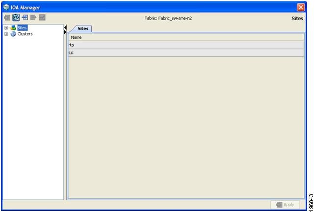
Figure 4-1 shows the IOA Manager interface.
Figure 4-1 IOA Manager Main Window
Toolbar
The IOA Manager main toolbar provides icons for accessing the most commonly used operations as shown in Table 4-1 .
|
|
|
|---|---|


Launching IOA Manager
To launch IOA Manager, follow these steps:
Step 1![]() Choose Tools > I/O Acceleration.
Choose Tools > I/O Acceleration.
You see the Cisco DCNM-SAN main window as shown in Figure 4-2.
Figure 4-2 Cisco DCNM-SAN Window
Note![]() When you select IOA Manager, it opens the tree for the fabric that is selected. If there is no active fabric, IOA Manager launches with the first fabric in the tree.
When you select IOA Manager, it opens the tree for the fabric that is selected. If there is no active fabric, IOA Manager launches with the first fabric in the tree.
Configuring Sites
A site is described as a named set of switches. You can click the sites node to view the list of defined sites. There are two tables in the information pane: one for the assigned switches on the top and the another one for unassigned switches below the assigned switches table. You can click the name of the site to display the details in the information pane. Only active sites can be used for creating a clusters.
Adding a New Site
To create a new site using IOA Manager, follow these steps:
Step 1![]() Select Sites in the navigation pane.
Select Sites in the navigation pane.
You see the IOA Manager window as shown in Figure 4-3.
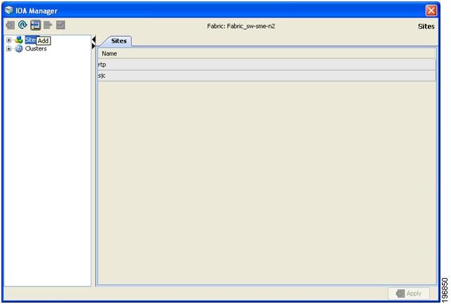
Step 2![]() Click the Add icon on the toolbar.
Click the Add icon on the toolbar.
You see the site name dialog box as shown in Figure 4-4.
Figure 4-4 Site Name Dialog Box
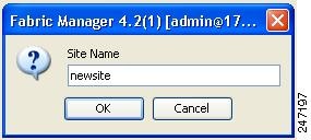
Step 3![]() Enter the site name and then click OK.
Enter the site name and then click OK.
You see the select switch dialog box as shown in Figure 4-5.
Figure 4-5 Select Switch Dialog Box
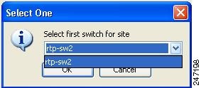
Step 4![]() Select a switch from the drop-down list box and then click OK.
Select a switch from the drop-down list box and then click OK.
Step 5![]() Click OK in the dialog box to confirm that you have successfuly created the site.
Click OK in the dialog box to confirm that you have successfuly created the site.
Removing a Site
To remove a site using IOA Manager, follow these steps:
Step 1![]() In the navigation pane, click the name of the site you want to delete.
In the navigation pane, click the name of the site you want to delete.
You see the IOA Manager window as shown in Figure 4-6.
Step 2![]() Click the Remove icon on the toolbar.
Click the Remove icon on the toolbar.
You see the confirmation dialog box in as shown in Figure 4-7.
Figure 4-7 Delete Confirmation Dialog Box
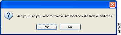
Step 3![]() Click Yes to confirm that you want to remove the site.
Click Yes to confirm that you want to remove the site.
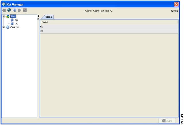
Viewing a Site
To view a site using IOA Manager, follow these steps:
Step 1![]() In the navigation pane, click Sites.
In the navigation pane, click Sites.
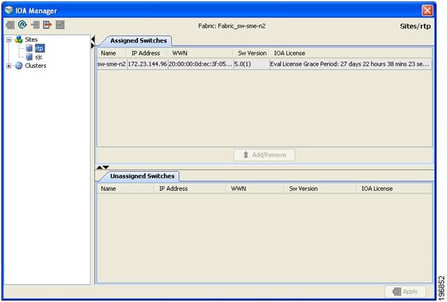
You see the IOA Manager window as shown in Figure 4-8.
Figure 4-8 Viewing Sites Using IOA Manager
Step 2![]() Expand the sites in the hierarchy.
Expand the sites in the hierarchy.
Step 3![]() Click the name of the site to view the details in the information pane.
Click the name of the site to view the details in the information pane.
You see the site details as shown in Figure 4-9.
Figure 4-9 Viewing Site Details Using IOA Manager
Adding Switches to a Site
To add a switch to a site, follow these steps:
Step 1![]() In the navigation pane, click Sites.
In the navigation pane, click Sites.
Step 2![]() Select the switches that you want to add from the Unassigned Switches table.
Select the switches that you want to add from the Unassigned Switches table.
Step 3![]() Click Add, and then click Apply.
Click Add, and then click Apply.
Removing Switches from a Site
To remove a switch from a site, follow these steps:
Step 1![]() In the navigation pane, click Sites.
In the navigation pane, click Sites.
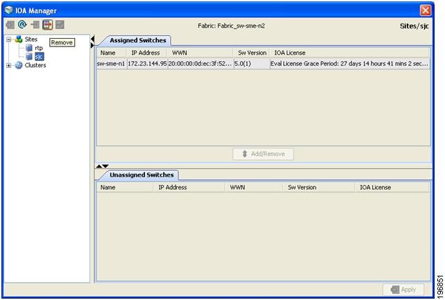
You see the IOA Manager window as shown in Figure 4-10.
Figure 4-10 Removing Switches from a Site Using IOA Manager
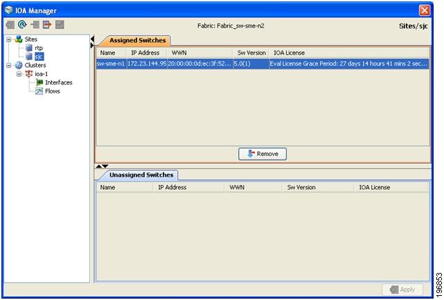
Step 2![]() Click to select the switches you want to remove from Assigned Switches table.
Click to select the switches you want to remove from Assigned Switches table.
Step 3![]() Click Remove, and then click Apply.
Click Remove, and then click Apply.
Configuring Clusters
You can select a cluster to see the details in the information pane. The upper table in the information pane displays the members of a named cluster, and the table below displays the statistical information about the cluster’s active IOA interfaces.
Adding a New Cluster
To create a new cluster using IOA Manager, follow these steps:
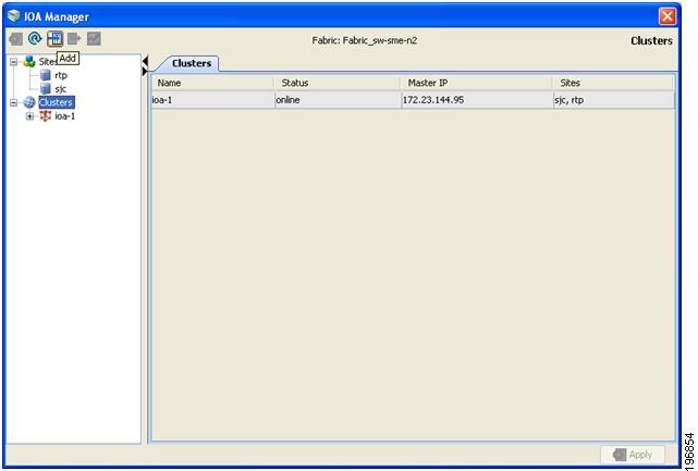
Step 1![]() Select Cluster in the navigation pane and then click the Add icon on the toolbar.
Select Cluster in the navigation pane and then click the Add icon on the toolbar.
You see the IOA Manager window as shown in Figure 4-11.
Figure 4-11 IOA Manager - Add Clusters
Step 2![]() Enter the Cluster name, and then click OK.
Enter the Cluster name, and then click OK.
You see the add Cluster name dialog box as shown in Figure 4-12.
Figure 4-12 Add Cluster Name Dialog box
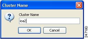
Step 3![]() Enter the Cluster name and then click OK.
Enter the Cluster name and then click OK.
You see the select switch dialog box as shown in Figure 4-13.
Figure 4-13 Select Switch Dialog Box
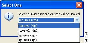
Step 4![]() Select a switch from the drop-down list, and then click OK.
Select a switch from the drop-down list, and then click OK.
Note![]() You need to select a switch that you would like it to be the master switch as the seed switch when you create the IOA cluster. If you have multiple switches in a site, you may add all the switches in a site that you would like to manage from to the cluster before adding the switches from the remote site.
You need to select a switch that you would like it to be the master switch as the seed switch when you create the IOA cluster. If you have multiple switches in a site, you may add all the switches in a site that you would like to manage from to the cluster before adding the switches from the remote site.
You see a message box upon successfully creating a cluster as shown in Figure 4-14.
Note![]() If the master switch that you selected is not a member of the site, you may either need to add the switch to an existing site or to create a new site.
If the master switch that you selected is not a member of the site, you may either need to add the switch to an existing site or to create a new site.
Removing a Cluster
To remove a site using IOA Manager, follow these steps:
Step 1![]() In the navigation pane, click the name of the cluster that you want to delete.
In the navigation pane, click the name of the cluster that you want to delete.
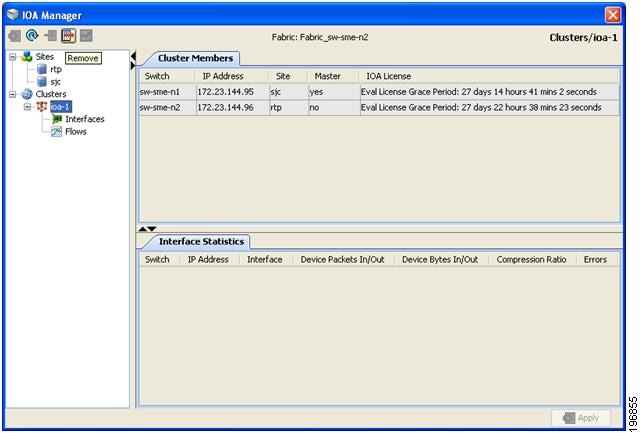
You see the IOA Manager window as shown in Figure 4-15.
Figure 4-15 Removing a Cluster Using IOA Manager
Step 2![]() Click the Remove icon on the toolbar.
Click the Remove icon on the toolbar.
You see the Delete confirmation dialog box as shown in Figure 4-16.
Figure 4-16 Remove Confirmation Dialog Box
Step 3![]() Click Yes to remove the cluster.
Click Yes to remove the cluster.
Viewing Clusters
To view a cluster using IOA Manager, follow these steps:
Step 1![]() Click clusters in the navigation pane.
Click clusters in the navigation pane.
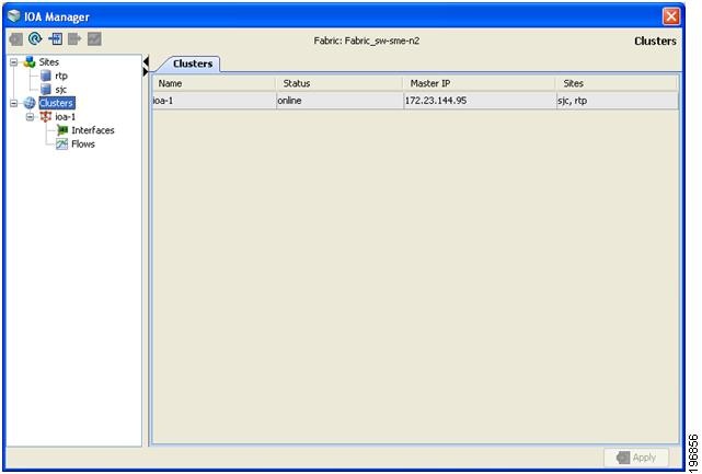
You see the IOA Manager window with clusters selected as shown in Figure 4-17.
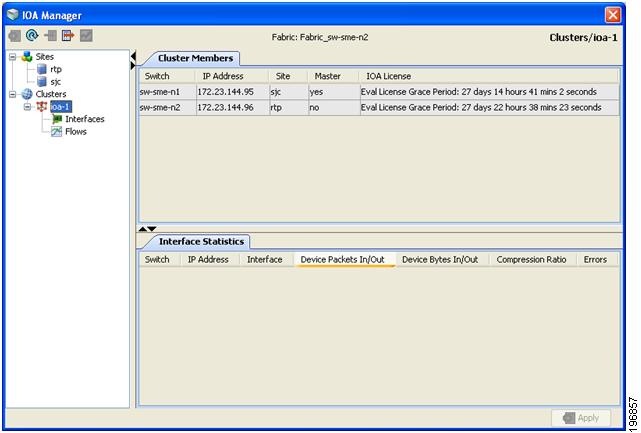
Figure 4-17 Viewing Clusters Using IOA Manager
Step 2![]() Expand the cluster in the hierarchy.
Expand the cluster in the hierarchy.
Step 3![]() Click the name of the cluster to view the details in the information pane.
Click the name of the cluster to view the details in the information pane.
You see the IOA Manager window with the cluster details as shown in Figure 4-18.
Figure 4-18 Viewing Cluster Details
Note![]() DCNM does not support configuration of multiple clusters with the same name in a fabric. This action is supported through CLI only.
DCNM does not support configuration of multiple clusters with the same name in a fabric. This action is supported through CLI only.
Configuring Interfaces
You can select the interfaces in a named cluster to see the details in the information pane. The upper table in the information pane displays information about active and configured IOA interface pairs associated with the cluster. The lower table in the information pane displays information about IOA interface candidates that are ready for use in the cluster.
Assigning Interfaces to a Cluster
To add a new interface to a cluster using IOA Manager, follow these steps:
Step 1![]() Expand the cluster node in the navigation pane and click Interfaces.
Expand the cluster node in the navigation pane and click Interfaces.
You see the IOA Manager window as shown in Figure 4-19.
Figure 4-19 Adding Interfaces Using IOA Manager
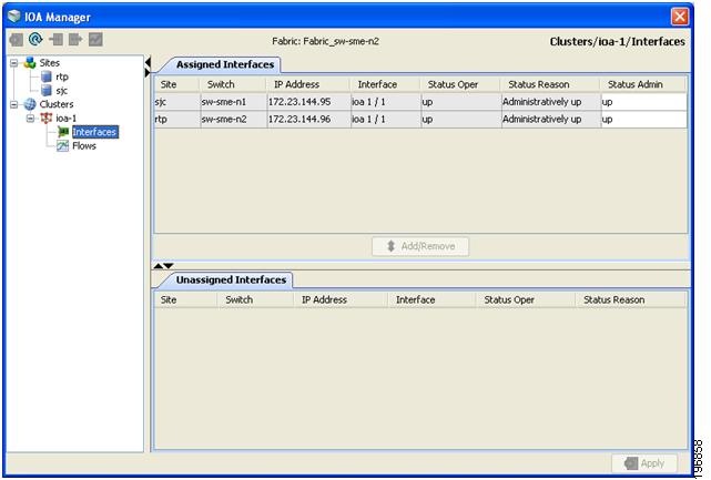
The information pane displays the Assigned Interfaces and Unassigned Interfaces tabs.
Step 2![]() Select one or more interfaces from the Unassigned Interfaces table in the information pane and then click Add.
Select one or more interfaces from the Unassigned Interfaces table in the information pane and then click Add.
Step 3![]() Click Apply to apply changes.
Click Apply to apply changes.
Note![]() You can change the administrative status of an assigned interface by selecting up or down from the admin status drop-down list box and then click Apply.
You can change the administrative status of an assigned interface by selecting up or down from the admin status drop-down list box and then click Apply.
Note![]() Cisco DCNM-SAN denotes all the candidate service engines that are not currently provisioned for any service as unconfigured in the unassigned interfaces table. When you select these interfaces, it will automatically provision these service engines for IOA, and configure them as a part of this IOA cluster.
Cisco DCNM-SAN denotes all the candidate service engines that are not currently provisioned for any service as unconfigured in the unassigned interfaces table. When you select these interfaces, it will automatically provision these service engines for IOA, and configure them as a part of this IOA cluster.
Removing Interfaces from a Cluster
To remove an interface from a cluster, follow these steps:
Step 1![]() Expand the cluster node in the navigation pane and click Interfaces.
Expand the cluster node in the navigation pane and click Interfaces.
You see the IOA Manager window as shown in Figure 4-20.
Figure 4-20 Removing Interfaces Using IOA Manager
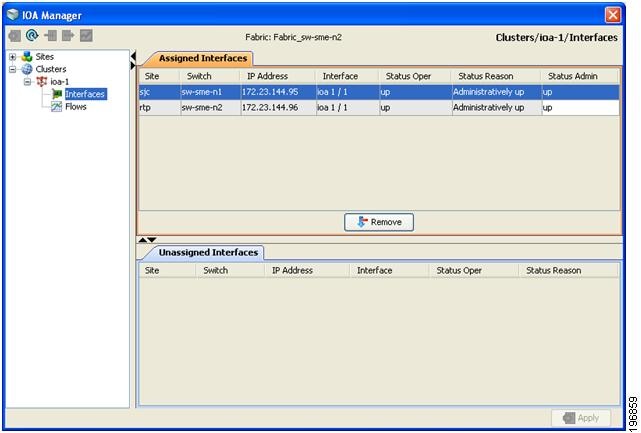
Step 2![]() Select the switches from the Assigned Interfaces table that you want to remove.
Select the switches from the Assigned Interfaces table that you want to remove.
Step 3![]() Click Remove to move the switches to Unassigned Interfaces table.
Click Remove to move the switches to Unassigned Interfaces table.
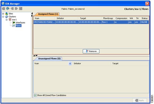
Configuring Flows
You can select the flows in a named cluster to see the details in the information pane. The upper table in the information pane displays information on active IOA flows. The lower table in the information pane displays information on candidate IOA flows.
Adding a Flow
To add a flow in the cluster using IOA Manager, follow these steps:
Step 1![]() Expand the Cluster node in the navigation pane and then click Flows.
Expand the Cluster node in the navigation pane and then click Flows.
You see the IOA Manager window displaying the Assigned Flows and Unassigned Flows as shown in Figure 4-21.
Note![]() If IVR zoneset is activated, Cisco DCNM-SAN will automatically consider the IVR zoneset and list the candidate IVR flows in the Unassigned flows section.
If IVR zoneset is activated, Cisco DCNM-SAN will automatically consider the IVR zoneset and list the candidate IVR flows in the Unassigned flows section.
Figure 4-21 Adding Flows Using IOA Manager
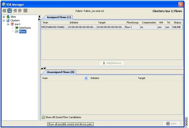
Step 2![]() Check the Click Show All Zoned Flow Candidates check box to display all the zoned members.
Check the Click Show All Zoned Flow Candidates check box to display all the zoned members.
Step 3![]() Select one or more switches from the Unassigned Flows in the information pane and then click Add.
Select one or more switches from the Unassigned Flows in the information pane and then click Add.
You see the Add Flows dialog box as shown in Figure 4-22.
Figure 4-22 Flow Configuration Dialog Box
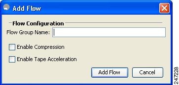
Step 4![]() Enter a flow group name.
Enter a flow group name.
Step 5![]() Check the Enable Compression check box to enable compression.
Check the Enable Compression check box to enable compression.
Step 6![]() Check the Enable Tape Acceleration check box to enable tape acceleration.
Check the Enable Tape Acceleration check box to enable tape acceleration.
Note![]() Write accleration is enabled by default.
Write accleration is enabled by default.
Figure 4-23 Configure Flow Dialog Box
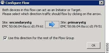
Step 7![]() Click the arrow icon to configure the flow in this direction.
Click the arrow icon to configure the flow in this direction.
Step 8![]() (Optional) Check the Use this directon for the rest of the Flow group check box to apply the same direction to rest of the flow group.
(Optional) Check the Use this directon for the rest of the Flow group check box to apply the same direction to rest of the flow group.
Note![]() You may use this step only if some of the N ports are registered as both initiators and targets, especially in cases of remote replication flow.
You may use this step only if some of the N ports are registered as both initiators and targets, especially in cases of remote replication flow.
Step 9![]() Click Add and then click Apply.
Click Add and then click Apply.
Removing a Flow
To add a flow in the cluster using IOA Manager, follow these steps:
Step 1![]() Expand the Cluster node in the navigation pane and then click Flows.
Expand the Cluster node in the navigation pane and then click Flows.
You see the IOA Manager window displaying the Assigned Flows and Unassigned Flows as shown in Figure 4-24.
Figure 4-24 Removing Flows Using IOA Manager
Step 2![]() Select one or more switches from the Assigned Flows in the information pane and then click Remove.
Select one or more switches from the Assigned Flows in the information pane and then click Remove.
Viewing Interface Statistics
To view real-time charts using IOA Manager, follow these steps:
Step 1![]() Expand the Cluster node in the navigation pane and click the name of the cluster.
Expand the Cluster node in the navigation pane and click the name of the cluster.
Step 2![]() Select a switch from the Interfaces Statistics table in the information pane.
Select a switch from the Interfaces Statistics table in the information pane.
You will see the IOA Manager window as shown in Figure 4-25.
Figure 4-25 Select IOA Manager Real-time Chart
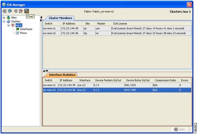
Step 3![]() Click the chart icon on the toolbar to monitor real-time charts.
Click the chart icon on the toolbar to monitor real-time charts.
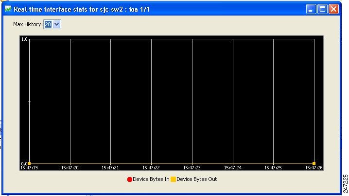
You see the chart as shown in Figure 4-26.
Figure 4-26 IOA Manager Real-time Chart
 Feedback