Setting Up Your CSP and Configuring Services
Summary Steps
Setting up your Cisco Cloud Services Platform (Cisco CSP) and creating services consists of the following high-level steps:
Procedure
| Step 1 |
Upgrade the Cisco CSP software or perform the initial setup. |
| Step 2 |
Log in to the Cisco CSP 2100. |
| Step 3 |
Generate and install an SSL certificate. |
| Step 4 |
Access Cisco CSP through the web interface. |
| Step 5 |
Upload the service image to the Cisco CSP. |
| Step 6 |
Create a service. |
| Step 7 |
Verify the service instance. |
Upgrading the Cisco CSP Software
You can upgrade the Cisco CSP software by installing an ISO image through any of the following methods:
-
Using the Cisco Integrated Management Controller (CIMC) KVM console: Map the ISO image to the Virtual CD/DVD by using the CIMC console and then install the image. The ISO image installation through CIMC console is useful for clean installations because the CIMC KVM or a direct console connected to the Cisco CSP system is required to perform the tasks described in Performing the Initial Setup.
-
Using the Cisco CSP 2100 CLI or REST APIs: Copy the update ISO image to the repository, specify the installation mode, and then install the image. The ISO image installation through CLI or REST APIs is more useful for software updates because the CIMC KVM or direct console support is not required to configure the system. After the installation is complete and the system reboots, the Cisco CSP 2100 system can be accessed through Secure Shell (SSH).
 Note |
Ensure that network connectivity is not lost while installation is in progress. Network issues might result in installation getting stuck in one of the various stages. In such a scenario, reinstall the ISO image, which means re-attach the ISO image to the KVM console and reboot Cisco CSP. |
Performing the Initial Setup
Before you begin
-
Make sure that the Cisco CSP is set up correctly and is cabled for network access. For information about setting up the Cisco CSP, see the Cisco Cloud Services Platform Hardware Installation Guide.
-
Choose a hostname for your Cisco CSP.
-
Obtain the following information about the Cisco CSP from your network administrator:
-
Port channel or physical network interface card (pNIC) to be used as the management interface
-
VLAN values for the management port channel, the management interface, and the dedicated service management interface (optional)
-
Two pNIC members for the port channel to be used as the management interface (optional)
-
Password for the admin user
-
Management IP address
-
Netmask for the management interface
-
Default gateway IP address
-
Domain name server (DNS) (optional)
-
Domain name
-
Port channel or pNIC to be used as the dedicated service management interface (optional)
-
Two pNIC members for the port channel to be used as the dedicated service management interface (optional)
-
Procedure
| Step 1 |
Turn on the Cisco CSP. |
||
| Step 2 |
Enter admin as the username and admin as the password. |
||
| Step 3 |
Enter yes or no depending upon whether you want to use a port channel for the management interface. Configuring a port channel as the management interface ensures that you always have connectivity with the Cisco CSP. You can connect to Cisco CSP even when one of the pNICs is down. Do one of the following:
|
||
| Step 4 |
Do the following to use a port channel as the management interface: |
||
| Step 5 |
Enter the pNIC interface number that you want to use as the management interface. The Linux
naming convention designates the four 1-GB Ethernet ports as enp4s0f0,
enp4s0f1, enp4s0f2, and enp4s0f3 and the two 10-GB Ethernet ports as enp7s0f0
and enp7s0f1. In addition, there are two 1-GB onboard Ethernet interfaces named
enp1s0f0 and enp1s0f1.
|
||
| Step 6 |
Enter yes or no to specify the shared or dedicated mode for the management interface. Do one of the following:
|
||
| Step 7 |
Enter yes or no depending upon whether you want to specify a VLAN for the management interface. Do one of the following:
|
||
| Step 8 |
Enter yes to save the settings. |
||
| Step 9 |
Enter a new password for the admin user and then enter the password again for verification. |
||
| Step 10 |
Enter the hostname. |
||
| Step 11 |
Enter the IP address of the management interface. |
||
| Step 12 |
Enter the netmask of the management interface. |
||
| Step 13 |
Enter the IP address of the default gateway. |
||
| Step 14 |
Enter yes or no depending upon whether you want to specify the DNS. Do one of the following:
|
||
| Step 15 |
Enter the domain name; for example, cisco.com. |
||
| Step 16 |
Enter yes to save the settings. |
||
| Step 17 |
Enter yes or no to configure the dedicated service management interface. Do one of the following:
|
||
| Step 18 |
Do the following to configure a port channel as the dedicated service management interface: |
||
| Step 19 |
Enter the pNIC interface number that you want to use as the dedicated service management interface. |
||
| Step 20 |
Enter yes to save the settings. Your specified settings are saved and you are connected to the Cisco CSP console.
|
The following example shows the prompts described in this procedure.
localhost login: admin
Password:


                **********************************************
                **********************************************
                **********************************************
                ****                                      ****
                ****  Cisco Cloud Services Platform       ****
                ****         Version 2.3.1          ****
                ****         Built on 2018-10-10          ****
                ****  Cisco Systems Inc, copyright 2018   ****
                ****                                      ****
                **********************************************
                **********************************************
                **********************************************


Verifying server information ...

        System Information
        Manufacturer: Cisco Systems Inc
        Product Name: CSP
        Version: 2.3.1

PNIC Remote Connectivity Information from LLDP
==================================================
PNIC enp1s0f0   : system = No lldp detectd      intf = No lldp detected         state = down

PNIC enp1s0f1   : system = sw-lab-n5k-3         intf = Ethernet100/1/46         state = up

PNIC enp7s0f0   : system = sw-lab-n5k-3         intf = Ethernet100/1/48         state = up

PNIC enp7s0f1   : system = No lldp detectd      intf = No lldp detected         state = down

PNIC enp4s0f0   : system = sw-lab-n5k-3         intf = Ethernet100/1/45         state = up

PNIC enp4s0f1   : system = sw-lab-n5k-3         intf = Ethernet100/1/47         state = up

PNIC enp4s0f2   : system = No lldp detectd      intf = No lldp detected         state = down

PNIC enp4s0f3   : system = No lldp detectd      intf = No lldp detected         state = down

Enable port channel for mgmt pnic (yes or no): no

Choose a PNIC for the management interface: enp1s0f0, enp1s0f1, enp7s0f0, enp7s0f1, enp4s0f0, enp4s0f1, enp4s0f2, enp4s0f3:
enp4s0f0
Allow management interface to be shared with service VMs (yes or no)?: yes

        Shared Management Interface Physical NIC        : enp4s0f0

Define a vlan for the mgmt interface(yes or no)?: yes
Choose a vlan for the management interface, valid values are between 1 and 4094: 180

       Management vlan set to        : 180

Do you want to save these settings (yes or no)?: yes

Please enter a password for the CSP admin user
The password must:
have at least 8 characters and at most 64 characters
have at least 1 digits
have at least 1 special character[allowed _-~#@=+^]
have at least 1 upper case character
have at least 1 lower case character
not have two or more same characters consecutively
not be an exact dictionary word match
Password:
Enter it again for verification:
Password:

Enter your hostname: csp1
Enter your management IP address: 1.2.3.4
Enter your netmask: 255.255.255.0
Enter your default gateway: 1.2.3.1
Do you want to configure a Domain Name Server (DNS) (yes or no)?: yes
Enter your Domain Name Server (DNS): 5.6.7.8
Enter your domain name: cisco.com

        System Hostname                 : csp1
        Management IP Address           : 1.2.3.4
        Management Netmask              : 255.255.255.0
        Management Gateway              : 1.2.3.1
        Domain Name Server (DNS)        : 5.6.7.8
        Domain Name                     : cisco.com

Do you want to save these settings (yes or no)?: yes

Saving configuration............

Do you wish to configure s Dedicated Service Management Port (yes or no)?: yes
Do you want to set the service mgmt port up as port channel (yes or no)?: yes
Port channel name: SRV-MGMT
Choose the first PNIC for the service mgmt port channel: enp1s0f0, enp1s0f1, enp7s0f0, enp7s0f1, enp4s0f0, enp4s0f1, enp4s0f2,
enp4s0f3: enp1s0f0

        Service Mgmt Pnic member 1 set to        : enp1s0f0

Choose the second PNIC for the service mgmt port channel: enp1s0f0, enp1s0f1, enp7s0f0, enp7s0f1, enp4s0f0, enp4s0f1, enp4s0f2,
enp4s0f3: enp1s0f1

        Service Mgmt Pnic member 2 set to        : enp1s0f1

Choose bond-mode for service mgmt port-channel(balance-slb or active-backup or balance-tcp)?: balance-slb
Choose lacp-type for service mgmt port-channel (active or passive or off)?: active
Choose vlan trunk for service mgmt port-channel: 72

        Service Mgmt Port Channel: SRV-MGMT
        Service Mgmt Member 1    : enp1s0f0
        Service Mgmt Member 2    : enp1s0f1
        Service Mgmt Bond Mode   : balance-slb
        Service Mgmt LACP type   : active
        Service Mgmt VLAN Trunk  : 72

Do you want to save these settings (yes or no)?: yes
CSP expects HyperThreading to be disabled in BIOS
No Cavium card in the system
No Cavium card in the system
Welcome to the Cisco Cloud Services Platform CLI

TAC support: http://www.cisco.com/tac
Copyright (c) 2015-2016, Cisco Systems, Inc. All rights reserved.
The copyrights to certain works contained in this software are
owned by other third parties and used and distributed under
license. Certain components of this software are licensed under
the GNU General Public License (GPL) version 2.0 or the GNU
Lesser General Public License (LGPL) Version 2.1. A copy of each
such license is available at
http://www.opensource.org/licenses/gpl-2.0.php and
http://www.opensource.org/licenses/lgpl-2.1.php

admin connected from 127.0.0.1 using console on csp1
csp1#
Logging In to the Cisco CSP
You can log in to the Cisco CSP by using one of the following modes: web interface (accessible through a web browser), CLI, or REST APIs (accessible through cURL tool or Windows PowerShell). However, before logging in to the web interface or using the REST APIs, you must install an SSL certificate using the CLI. For detailed information about the CLI and available commands, see the Cisco Cloud Services Platform Command Reference Guide.
Generating and Installing an SSL Certificate
Note |
For proof-of-concept (POC) or lab deployments, an SSL certificate is not required. You can skip this section and go to Accessing the Cisco CSP Web Interface. |
You must generate a Certificate Signing Request (CSR) to send to a Certification Authority (CA) to obtain an SSL certificate and use the CLI to install the SSL certificate on Cisco CSP. The default self-signed certificate installed on the Cisco CSP is only for temporary use.
Procedure
| Step 1 |
Log in to the Cisco CSP 2100 CLI in EXEC mode. |
||
| Step 2 |
On the command prompt, use the following command to create a CSR: After you enter the command, you are prompted for some information such as country name, state, city, email, common name, and so on. For detailed information about this command, see the Cisco Cloud Services Platform Command Reference Guide .
|
||
| Step 3 |
Provide the required information in the prompt. After you provide the required information, the following two files are generated in the /osp/certificates directory:
|
||
| Step 4 |
Send the myhost.csr file to a CA to obtain an SSL certificate. After you submit the CSR to a CA, the CA generates an SSL certificate and sends a certificate file to you. The CA may also send a certificate chain file. |
||
| Step 5 |
Copy the SSL certificate files that you received from the CA to the /osp/certificates directory using the scp command from an external server. |
||
| Step 6 |
On the Cisco CSP 2100 command prompt, enter the following command to install the certificate: After you enter the command, you are prompted for some information such as localhost (hostname including the domain name), key filename, certificate filename, and chain filename. For detailed information about this command, see the Cisco Cloud Services Platform Command Reference Guide. |
||
| Step 7 |
Provide the required information in the prompt. After you provide the required information, the SSL certificate is installed. To verify that the certificate is installed, follow the instructions in the next section to log in to the Cisco CSP web interface by using a web browser. After logging in, click the lock icon in the address bar to see information about the installed certificate. |
Accessing the Cisco CSP Web Interface
Procedure
| Step 1 |
Enter https:// hostname or https:// ip-address in a web browser.
|
||
| Step 2 |
Enter the username admin and the password. The Cisco CSP web interface is displayed. 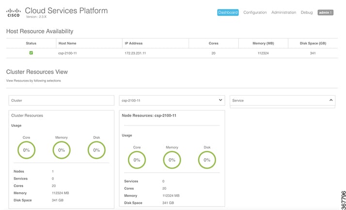 |
Overview of the Cisco CSP Web Interface
The Cisco CSP web interface consists of the following tabs and pages:
-
Dashboard: The Dashboard tab consists of the following pages:
-
Overview: Use the Overview page to view information about the host resources. You can filter resources by clusters, nodes, and services.
-
Services View: Use the Services View page to view information about the services traffic rate.
-
Network View: Use the Network View page to view information about statistics for a VNIC.
-
PNIC Statistic: Use the PNIC Statistic page to view information about statistics for a pNIC.
-
Resource Utilization Graph: Use the Resource Utilization Graph page to view statistical information about memory, disk, and CPU for a specific duration. You can choose a specific duration and get memory, disk, and CPU statistics for that time interval.
-
-
Configuration: The Configuration page consists of the following pages:
-
Repository: Use the Repository page to upload or remove an image and to view all available images.
-
Services: Use the Services page to create a new service or configure existing services, change the power mode of a service, and export a service. You can create a new service using a template or save a service as a template.
-
Service Template: Use the Services Templates page to view all available service templates and delete a service template.
-
pNICs: Use the pNICs page to view information about pNICs and port channels and to configure or unconfigure a pNIC as the management interface.
-
Port Channel: Use the Port Channel page to create a port channel, delete or edit a port channel, and to configure or unconfigure a port channel as the management interface.
-
SRIOV: Use the SRIOV page to enable, disable, configure, or unconfigure an SR-IOV interface.
-
System Settings: Use the System Settings page to enable or disable CPU pinning.
-
-
Administration: The Administration page consists of the following pages:
-
Password: Use the Password page to change the password for the admin user.
-
Host: Use the Host page to configure the host. You can configure the hostname, host domain name, DNS server, host IP, gateway IP, management MTU, management pNIC mode, and session idle timeout.
-
NTP Server: Use the NTP Server page to configure an NTP server.
-
VNF Group: Use the VNF Group page to configure a VNF group name of a service.
-
User: Use the User page to create, modify, or delete a local user.
-
Cluster: Use the Cluster page to create, configure, and delete clusters.
-
NFS: Use the NFS page to create and configure NFS storage.
-
SNMP: Use the SNMP page to create and configure SNMP agent, communities, users, groups, and traps.
-
AAA: Use the AAA page to specify the AAA authentication mode and to create, modify, or delete a TACACS+ or RADIUS server.
-
IP Receive ACL: Use the IP Receive ACL page to configure the Access Control List (ACL) access for the management interface. You can specify the source network IP address, service type, priority, and action for the packets received from the specified source network.
-
Syslog: Use the Syslog page to configure multiple syslog servers. You can send internal log messages to multiple remote syslog server on TCP and UDP ports, or only on UDP port.
-
Uploading Service Images Using the Cisco CSP Web Interface
Before you begin
Be sure to download the service image to your local machine or a location on your local network that is accessible to your Cisco CSP.
Procedure
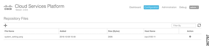
| Step 1 |
Click the Configuration tab and then choose Repository. |
||
| Step 2 |
On the Repository Files page, click the add button (+). |
||
| Step 3 |
Click Browse. |
||
| Step 4 |
Navigate to the service image, select a service image, and click Open. |
||
| Step 5 |
Click Upload. After the service image is uploaded, the image name and other relevant information are displayed in the Repository Files table.
 |
Creating a Service Instance
Procedure
| Step 1 |
Click the Configuration tab and then choose Services. |
||||
| Step 2 |
On the Service page, click the add (+) button. The Create Service page is displayed. |
||||
| Step 3 |
In the Name field, enter a name for the service. |
||||
| Step 4 |
From the Target Host Name drop-down list, choose the target host. |
||||
| Step 5 |
(Optional) In the VNF Management IP field, enter the VNF management IP address to be used in the service.
|
||||
| Step 6 |
From the Image Name drop-down list, choose an image file for the service. You can use an ISO or OVA, or a QCOW software image file to create the service.
Depending on the type of image selected, additional fields are displayed. If your service requires additional information, as is the case with Cisco VSM and Cisco VSG services, you must enter this information in the Additional Image Questionnaires section. For details about the additional information that your service requires, see the documentation for that service. |
||||
| Step 7 |
(Optional) Click Day Zero Config and in the Day Zero Config dialog box, do the following:
|
||||
| Step 8 |
(Optional) In the Number of Cores field, specify the number of cores. Make sure that the new value does not exceed the available resources. |
||||
| Step 9 |
(Optional) If you want to resize the disk, check the Do you want to resize disk? check box. This option is available only when a QCOW2 image is selected in the Image Name field. |
||||
| Step 10 |
(Optional) In the Disk Space (GB) field, specify the disk space. Make sure that the new value does not exceed the available resources. This field is not editable when a QCOW2 image is selected in the Image Name field and the Do you want to resize disk? check box is unchecked. |
||||
| Step 11 |
(Optional) In the RAM (MB) field, specify the RAM. Make sure that the new value does not exceed the available resources. |
||||
| Step 12 |
(Optional) If you want to deploy the service on an NFS storage, select the NFS Storage check box and then select an NFS storage from the NFS drop-down list. |
||||
| Step 13 |
(Optional) In the Disk Type field, specify the disk type. Valid choices are IDE or VIRTIO. |
||||
| Step 14 |
Click VNIC and in the VNIC Configuration dialog box, do the following: To add more vNICs, click VNIC and repeat all tasks described in this step. |
||||
| Step 15 |
(Optional) Click Storage and in the Storage Configuration dialog box, do the following: To add more storage, click Storage and repeat all tasks described this step. |
||||
| Step 16 |
(Optional) In the VNC Port field, enter a VNC port for the service. Valid range is from 8721 to 8784. |
||||
| Step 17 |
(Optional) In the VNC Password field, enter a password and then enter the same password in the Confirm VNC Password field.
|
||||
| Step 18 |
Click Serial Port and in the Serial Port dialog box, do the following:
To add more serial ports, click Serial Port and repeat all tasks described in this step. |
||||
| Step 19 |
(Optional) If you are configuring the services in redundancy, select the HA Service Configuration check box. The Cisco CSPs must be in the cluster mode. Do the following: |
||||
| Step 20 |
Click Deploy. The Service Test Creation dialog box is displayed indicating that the service is available. |
Verifying Your Service Instance
Make sure that your service instance is up and running.
Procedure
| Step 1 |
Click the Configuration tab and then choose Services. The Service table shows the current status of services. |
| Step 2 |
Find your service instance in the Service Name column, and check that the state is deployed and the power status is on. |
Configuring Multiple Syslog Servers
Ensure that CSP service instance is up and running.
Procedure
| Step 1 |
Click the Administration tab, and then select Syslog. |
| Step 2 |
On the Syslog page, you can perform either of the following:
|
| Step 3 |
If you select UDP as the mechanism to send log messages, in the UDP Port field, specify the UDP port values of the remote syslog server. |
| Step 4 |
If you do not select UDP as the mechanism to send log messages, specify both TCP and UDP port values of the remote syslog server. |
| Step 5 |
To add a remote syslog server, click the + button. |
| Step 6 |
In the Host field, specify the IPv4 IP address or host name of the remote syslog server, and then click Add. The newly added host is displayed in a table.
|
| Step 7 |
To add multiple syslog servers, repeat step 5 through step 6. You can add up to eight syslog servers. |
 Feedback