Cisco Cloud Services Platform 2100 Quick Start Guide, Release 2.0.0
Available Languages
Contents
- Setting Up Your Cisco CSP 2100 and Configuring Services
- Summary Steps
- Upgrading the Cisco CSP 2100 Software
- Performing the Initial Setup
- Logging In to the Cisco CSP 2100
- Generating and Installing an SSL Certificate
- Accessing the Cisco CSP 2100 Web Interface
- Overview of the Cisco CSP 2100 Web Interface
- Uploading Service Images Using the Cisco CSP 2100 Web Interface
- Creating a Service Instance
- Verifying Your Service Instance
First Published: March 22, 2016
Last Updated: August 03, 2017
Setting Up Your Cisco CSP 2100 and Configuring Services
Summary Steps
ProcedureSetting up your Cisco Cloud Services Platform 2100 (Cisco CSP 2100) and creating services consists of the following high-level steps:
Upgrading the Cisco CSP 2100 Software
You can upgrade the Cisco CSP 2100 software to release 2.0.0 by using an ISO image. The process for upgrading the Cisco CSP 2100 software is similar to the process for installing Cisco CSP 2100. All existing configurations and settings are retained after an upgrade.
To do a new installation without retaining the existing configurations and settings, run the following command before upgrading the Cisco CSP 2100 software and then follow the instructions in Performing the Initial Setup.
csp# system install mode clean-install
results success
Performing the Initial Setup
Before You BeginProcedureMake sure that the Cisco CSP 2100 is set up correctly and is cabled for network access. For information about setting up the Cisco CSP 2100, see the Cisco Cloud Services Platform 2100 Hardware Installation Guide.
Choose a hostname for your Cisco CSP 2100.
Obtain the following information about the Cisco CSP 2100 from your network administrator:
Note
Although not required, we recommend that you change the default password of your Cisco CSP 2100 during the initial setup to a password of your choice.
The following example shows the prompts described in this procedure.
localhost login: admin
Password:
Last login: Fri Feb 26 11:16:06 on ttyl

                **********************************************
                **********************************************
                **********************************************
                ****                                      ****
                ****  Cisco Cloud Services Platform 2100  ****
                ****           Version 2.0.0              ****
                ****         Built on 2016-02-22          ****
                ****  Cisco Systems Inc, copyright 2016   ****
                ****                                      ****
                **********************************************
                **********************************************
                **********************************************

Verifying server information ...
                System Information
                Manufacturer: Cisco Systems Inc
                Product Name: CSP-2100
                Version: 2.0.0

PNIC Remote Connectivity Information from LLDP
================================================
PNIC enp1s0f0   : system = sw-lab-n5k-1         intf = Ethernet103/1/44     state = up
PNIC enp1s0f1   : system = sw-lab-n5k-1         intf = Ethernet103/1/45     state = up
PNIC enp7s0f0   : system = sw-lab-n5k-2         intf = Ethernet1/17         state = up
PNIC enp7s0f1   : system = sw-lab-n5k-1         intf = Ethernet1/17         state = up
PNIC enp4s0f0   : system = sw-lab-n5k-1         intf = Ethernet104/1/35     state = up
PNIC enp4s0f1   : system = sw-lab-n5k-1         intf = Ethernet104/1/36     state = up
PNIC enp4s0f2   : system = sw-lab-n5k-1         intf = Ethernet104/1/37     state = up
PNIC enp4s0f3   : system = sw-lab-n5k-1         intf = Ethernet104/1/38     state = up


Choose a PNIC for the management interface: enp1s0f0, enp1s0f1, enp7s0f0, enp7s0f1, enp4s0f0, enp4s0f1, enp4s0f2, enp4s0f3  :
enp4s0f0
            Management Interface Physical NIC       : enp4s0f0

Do you want to save this setting (yes or no)?: yes
Enter your hostname: mycsp
Enter your management IP address: 192.0.2.1
Enter your netmask: 255.255.255.0
Enter your default gateway: 192.0.2.130
Do you want to configure a Domain Name Server (DNS) (yes or no)? yes
Enter your Domain Name Server (DNS): 198.51.100
Enter your domain name: Cisco.com

           System Hostname                   : mycsp
           Management IP Address             : 192.0.2.1
           Management Netmask                : 255.255.255.0
           Management Gateway                : 192.0.2.130
           Domain Name Server (DNS)          : 198.51.100
           Domain Name                       : cisco.com

Do you want to save these settings (yes or no)? yes

Saving configuration .........

No Cavium card in the system
All VSBs started. count = 0
Do you want to change the admin password (yes or no)? yes

Please enter a password for the CSP-2100 admin user
Password:
Enter it again for verification:
Password:

Broadcast message from root@mycsp (tty1) (Fri Feb 26 11:18:00 2016):
*** admin password has just been changed ***
Welcome to the Cisco Cloud Services Platform CLI
Logging In to the Cisco CSP 2100
You can log in to the Cisco CSP 2100 by using one of the following modes: web interface (accessible through a web browser), CLI, or REST APIs (accessible through cURL tool or Windows PowerShell). However, before logging in to the web interface or using the REST APIs, you must install an SSL certificate using the CLI. For detailed information about the CLI and available commands, see the Cisco Cloud Services Platform 2100 Command Reference Guide.
Generating and Installing an SSL Certificate
Procedure
Note
For proof-of-concept (POC) or lab deployments, an SSL certificate is not required. You can skip this section and go to Accessing the Cisco CSP 2100 Web Interface.
You must generate a Certificate Signing Request (CSR) to send to a Certification Authority (CA) to obtain an SSL certificate and use the CLI to install the SSL certificate on Cisco CSP 2100. The default self-signed certificate installed on the Cisco CSP 2100 is only for temporary use.
Step 1 Log in to the Cisco CSP 2100 CLI in EXEC mode. Step 2 On the command prompt, use the following command to create a CSR: csp# certificate request sha sha256 keysize 2048After you enter the command, you are prompted for some information such as country name, state, city, email, common name, and so on. For detailed information about this command, see the Cisco Cloud Services Platform 2100 Command Reference Guide.
Note The common name is the DNS name of the host, including the domain name; for example, myserver.mycompany.com.
Step 3 Provide the required information in the prompt. After you provide the required information, the following two files are generated in the /osp/certificates directory:
myhost.csr—The server certificate request file
myPrivate.key—The server key file
Note To enable the Cisco CSP 2100 to start without entering a password, the myPrivate.key file is not protected with a passphrase. However, you can use a passphrase to protect it. When the myPrivate.key file is protected with a passphrase, the administrator must enter the password every time the Cisco CSP 2100 starts.
Step 4 Send the myhost.csr file to a CA to obtain an SSL certificate. After you submit the CSR to a CA, the CA generates an SSL certificate and sends a certificate file to you. The CA may also send a certificate chain file.
Step 5 Copy the SSL certificate files that you received from the CA to the /osp/certificates directory using the scp command from an external server. Step 6 On the Cisco CSP 2100 command prompt, enter the following command to install the certificate: csp# certificate install-certificateAfter you enter the command, you are prompted for some information such as localhost (hostname including the domain name), key filename, certificate filename, and chain filename. For detailed information about this command, see the Cisco Cloud Services Platform 2100 Command Reference Guide.
Step 7 Provide the required information in the prompt. After you provide the required information, the SSL certificate is installed.
To verify that the certificate is installed, follow the instructions in the next section to log in to the Cisco CSP 2100 web interface using a web browser. After logging in, click the lock icon in the address bar to see information about the installed certificate.
Accessing the Cisco CSP 2100 Web Interface
Procedure
Step 1 Enter https://hostname or https://ip-address in a web browser.
Note The hostname should resolve to the IP address that you entered as the management IP address in Step 5 of Performing the Initial Setup. The hostname should also match the hostname specified in Step 2 of Generating and Installing an SSL Certificate.
Step 2 Enter the username admin and the password. The Cisco CSP 2100 web interface is displayed.
Overview of the Cisco CSP 2100 Web Interface
The Cisco CSP 2100 web interface consists of the following tabs and pages:
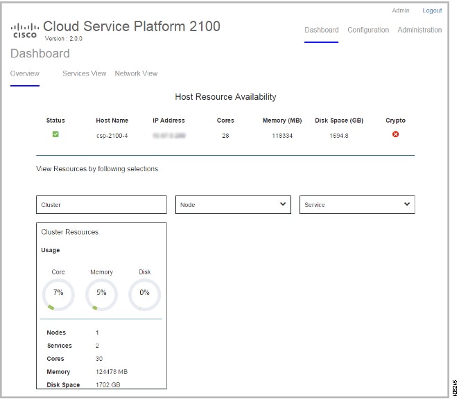
Dashboard: The Dashboard page consists of the following tabs and pages:
Overview: Use the Overview page to view information about the host resources. You can filter resources by clusters, nodes, and services.
Services View: Use the Services View page to view information about the services traffic rate.
Network View: Use the Network View page to view information about pNIC statistics for host members.
Configuration: The Configuration page consists of the following tabs and pages:
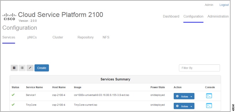
Services: Use the Services page to create or configure services, change the power mode of a service, and export a service. You can create a new service using a template, save a service as a template, and delete a template by using the Service Creation page.
pNICs: Use the pNICs page to configure pNICs. You can also configure a port channel or a passthrough as a network interface.
Cluster: Use the Cluster page to create and configure clusters.
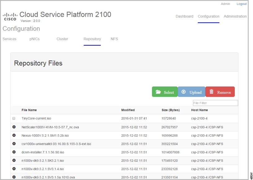
Repository: Use the Repository page to upload or remove an image and to view all available images.
NFS: Use the NFS page to create and configure NFS storage.
Administration: The Administration page consists of the following tabs and pages:
Uploading Service Images Using the Cisco CSP 2100 Web Interface
Before You BeginProcedureBe sure to download the service image to your local machine or a location on your local network that is accessible to your Cisco CSP 2100.
Step 1 Click the Configuration tab and then click the Repository tab. Step 2 On the Repository Files page, click Select. Step 3 Navigate to the service image, select a service image, and click Open. Step 4 Click Upload. After the service image is uploaded, the image name and other relevant information are displayed in the Repository Files table.
Creating a Service Instance
Procedure
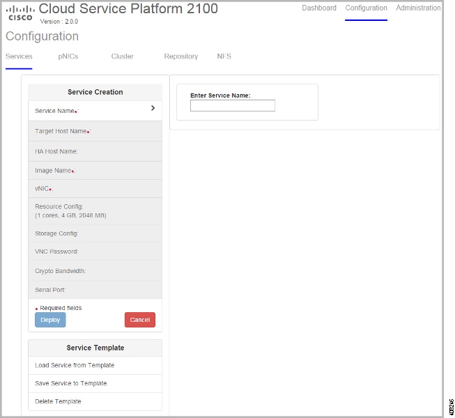
Step 1 Click the Configuration tab and then click the Services tab. Step 2 On the Services page, click Create. The Service Creation page is displayed.
Step 3 Enter a name for the service in the Enter Service Name field and press Enter. Step 4 Click Target Host Name and choose a target host from the available hosts. Step 5 (Optional) If you are configuring the target host with redundancy, click HA Host Name and choose another host from the available hosts. The selected hosts are configured as an HA pair. Step 6 Click Image Name and choose an image file from the list. You can use an ISO or OVA, or a QCOW software image file to create the service.
Note With Cisco VSM and Cisco VSG services, only ISO image files are supported.
Depending on the type of image selected, additional fields are displayed. If your service requires additional information, as is the case with the Cisco VSM and Cisco VSG services, you must enter this information in the Additional Image Info Required area and click Save. For details about the additional information that your service requires, see the documentation for that service.
Step 7 Click vNIC. Step 8 Click vNIC Number and do the following:
Step 9 (Optional) Click Resource Config to change the service resource configuration. The Number of Cores, Disk Space (GB), and RAM (MB) fields show the resources currently available for your service. You can accept the default values or change them to different values as long as the new values do not exceed the available resources. You can also check the NFS check box to select an NFS location.
Note You can select an NFS location only if it has been added previously. To add an NFS location, click the Configuration tab and then click the NFS tab and provide the required information.
Step 10 (Optional) Click Storage Config and then click StorageNumber and do the following:
- Click Location and select a location in the Storage Disk Location field.
- Click Type and choose a disk type. Valid choices are disk and cdrom.
- Click Format and choose a disk format. Valid choices are raw and qcow2.
- Click Size (GB) and enter the disk size in the Enter storage size (GB) field.
- When you are satisfied with the storage configuration, click Save.
- To add more storage space, click Add Storage and repeat Step 10.
Step 11 (Optional) Click VNC Password and enter a password in the Enter VNC Password field and the Repeat Password field.
Caution We strongly advise that you secure your remote access with a complex alphanumeric password for VNC.
Step 12 (Optional) If you are using the Cavium NITROX security processor card, click Crypto Bandwidth and specify the bandwidth. Step 13 Click Serial Port and do the following:
- Click SerialPortNumber.
- Click Type and choose a port type. Valid choices are telnet and console.
- Click Service Port and enter a value in the Enter Service Port Number field.
- When you are satisfied with the serial port configuration, click Save.
- To add more serial ports, click Add Service Port and repeat Step 13.
Step 14 Click Deploy.
Copyright © 2016-2017, Cisco Systems, Inc. All rights reserved.

 Feedback
Contact Cisco
- Open a Support Case

- (Requires a Cisco Service Contract)