New and Changed Information
The following table provides an overview of the significant changes up to this current release. The table does not provide an exhaustive list of all changes or of the new features up to this release.
|
Cisco APIC Release Version |
Feature |
Description |
|---|---|---|
|
25.0(2) |
Support for transit gateway external networking in Cisco Cloud APIC. |
Beginning with release 25.0(2), several external networking enhancements are available for the AWS transit gateway feature:
See Transit Gateway External Networking for more information. |
|
5.2(1) |
Support for Amazon Web Services (AWS) Transit Gateway Connect in Cisco Cloud APIC. |
By using the AWS Transit Gateway Connect feature:
|
|
5.0(1) |
Support for Amazon Web Services (AWS) Transit Gateway in Cisco Cloud APIC. |
This new feature automates intercloud, intracloud, and cloud-to-on-premise network connectivity. Using AWS Transit Gateway provides greater bandwidth over other solutions and simplifies communication between virtual private clouds (VPCs). |
AWS Transit Gateway with Cisco Cloud APIC
Beginning in Cisco Cloud Application Policy Infrastructure Controller (APIC) Release 5.0(1), you can use Amazon Web Services (AWS) Transit Gateway with Cisco Cloud APIC. AWS Transit Gateway is a service that functions as an internal router to automate connectivity between virtual private clouds (VPCs). The VPCs can be in different AWS regions in a cloud site.
Virtual private clouds (VPC) can't communicate with each other without additional configuration. Without using AWS Transit Gateway, you can configure inter-VPC communication by configuring VPC peering. Alternatively, you can use VPN tunnels and Cisco Cloud Services Routers (CSRs).
However, when you use AWS Transit Gateway with Cisco Cloud APIC, you connect VPCs or VRFs in the cloud site simply by associating the VPCs or VRFs to the same AWS Transit Gateways.
Every AWS region can have at least one AWS Transit Gateway. All the VPCs in the region can be attached to the local AWS Transit Gateway.
An AWS Transit Gateway, similar to a Cisco CSR, is owned by the infra tenant. However, it is shared with multiple user accounts.
Cisco APIC Release 5.0(1) is backward-compatible with previous methods of configuring communication between VPCs.
Benefits of Using AWS Transit Gateway with Cisco Cloud APIC
Using AWS Transit Gateway with Cisco Cloud Application Policy Infrastructure Controller (APIC) provides several benefits:
-
Higher performance: AWS Transit Gateway provides significantly more bandwidth than other methods of communication between VPCs. For example, AWS Transit Gateway provides up to 50 Gbps bandwidth for each VPC connection while VPN connections over Internet Protocol Security (IPsec) tunnels are limited to 1.5 Gbps.
-
Simplicity: AWS Transit Gateway is a network transit hub that interconnects multiple AWS VPCs. Before the introduction of AWS Transit Gateway, interconnectivity among multiple AWS VPCs was achieved by using fully meshed VPC peering or a transit VPC design, both of which add operational complexity. However, AWS Transit Gateway significantly simplifies the inter-VPC connectivity.
-
Potential lower cost: When using AWS Transit Gateway, you do not need a Cisco Cloud Services Router (CSR) or license if you are connecting VPCs in the same AWS region.
You still need CSRs for connectivity to the on-premises sites or to other cloud sites. If you need inter-region connectivity between AWS regions that do not support Transit Gateway peering, you still need to use VGWs and CSRs for connectivity.
-
Scalability: Using VPN tunnels limits the number of BGP routes. However, because AWS Transit Gateway attaches directly to VPCs, it dispenses with using BGP and so supports a greater number of connections.
You can attach 5000 VPCs to each AWS Transit Gateway. Groups of AWS Transit Gateways—called hub networks in the Cisco Cloud APIC solution—support 5000 VPC connections for each region.
AWS Transit Gateway Terminology
This section introduces some of the AWS Transit Gateway key terminology and concepts:
- AWS Transit Gateway
- A service that enables you to automate and simplify communication between virtual private clouds (VPCs).
- Attachment
- Association
- Propagation
For more information, see the article How transit gateways work in the Documentation section of the AWS website.
AWS Transit Gateway Resource Sharing
A hub network is a group of Amazon Web Service (AWS) Transit Gateways that allow you to share resources to make virtual private cloud (VPC) connections without having to manage the complexity of AWS Transit Gateway setup. A hub network is owned and maintained by the infra tenant; user tenants can choose to have their VPCs join any available hub network.
You can create an AWS Transit Gateway after you set up Cisco Cloud Application Policy Infrastructure Controller (APIC) for the first time. When you deploy a Cisco Cloud Services Router (CSR) in a region, two AWS Transit Gateways for each hub network are created in that region. This occurs when users deploy VPCs and specify that the VPCs use AWS Transit Gateway for inter-VPC connectivity.
Alternatively, you may already have a CSR deployed in one region and want to use AWS Transit Gateways in a second region without a CSR. In that case, you can create a user tenant, create a virtual private cloud (VPC), and then attach the VPC to a hub network. Doing so creates the AWS Transit Gateways in the second region, which shares the first region's CSR.
The AWS Transit Gateway on the infra account is automatically shared with user accounts whenever a user VPC joins a hub network belonging to the infra tenant. That enables the user to leverage the same pair of AWS Transit Gateways created on the infra account.
The following diagram shows the details of a setup with three AWS accounts. Oregon is the home region where Cisco Cloud APIC is deployed. The Cisco Cloud APIC administrator creates the hub network to include four regions: Sydney, Oregon, Ireland, and Mumbai.
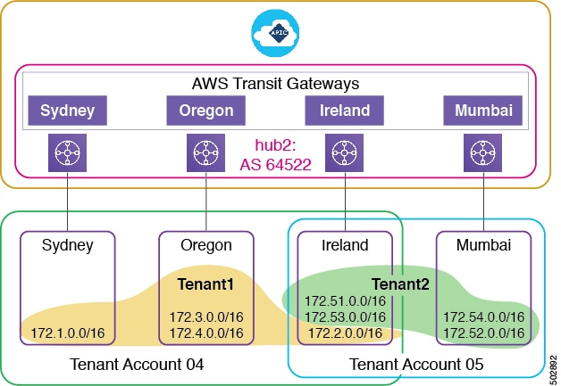
After the first-time Cisco Cloud APIC setup and CSR deployment, two AWS Transit Gateways are created in the Oregon home region. After the Cisco Cloud APIC administrator performs tenant onboarding—including creating the tenant, VRF, application profile, and endpoint group (EPG)—a new AWS Transit Gateway pair is created in all regions where the user VPCs have attached themselves to a hub network.
Account 04 maps to Tenant1, which has EPGs in the Sydney, Oregon, and Ireland regions. Cisco Cloud APIC creates two pairs of AWS Transit Gateways, one pair in the Sydney region and one pair in the Ireland region. Cisco Cloud APIC did not need to create a new AWS Transit Gateway pair in the Oregon region because a pair was created there after Cisco Cloud APIC first-time setup and CSR deployment. Cisco Cloud APIC creates an AWS Transit Gateway pair in the Mumbai region and shares them with Account 05. Cisco Cloud APIC did not need to create a new AWS Transit Gateway pair in the Ireland region because a pair was created in that region in connection with Account 04.
In summary, Cisco Cloud APIC creates a pair of AWS Transit Gateways in every region where you want a VPC to join that AWS Transit Gateway's hub network. These AWS Transit Gateways are shared to all user accounts that have VPC memberships in the hub network.
Scenarios for Using AWS Transit Gateway
Cisco Cloud Application Policy Infrastructure Controller (APIC) can use Amazon Web Services (AWS) Transit Gateway to establish network connectivity for different scenarios, including:
-
Inter-virtual private cloud (VPC) connectivity within an AWS Transit Gateway region
-
Connectivity between VPCs in different AWS regions using AWS Transit Gateway peering
-
Connectivity between an AWS cloud site and the on-premises Cisco Cloud APIC data center site or another Cisco Cloud APIC site.
The following three sections describe the network design for these scenarios.
Communication Between VPCs Within an AWS Region
A common use for Amazon Web Services (AWS) Transit Gateway is to enable communication between virtual private clouds (VPCs) within the same AWS region.
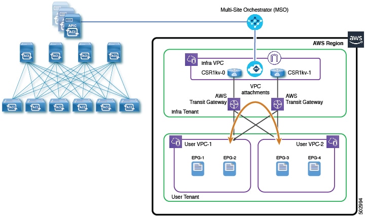
Before the availability of AWS Transit Gateway, Cisco Cloud Application Policy Infrastructure Controller (APIC) used the transit VPC design with VPN tunnels between AWS Virtual Gateways (VGWs) in user VPCs and Cisco Cloud Services Routers (CSRs) in the Infra VPC to provide inter-VPC connectivity.
With AWS Transit Gateway, the inter-VPC connectivity is significantly simplified. Cisco Cloud APIC programs VPC attachments on the AWS Transit Gateways for user VPCs that need to communicate with other VPCs in the region. The VPC-to-VPC communication goes through the AWS Transit Gateways.
 Note |
Beginning with release 5.2(1), AWS Transit Gateway Connect provides another solution for communication between VPCs within an AWS region using a single AWS Transit Gateway. For more information, see Differences Between Inter-Site Communication With AWS Transit Gateway Peering and AWS Transit Gateway Connect. |
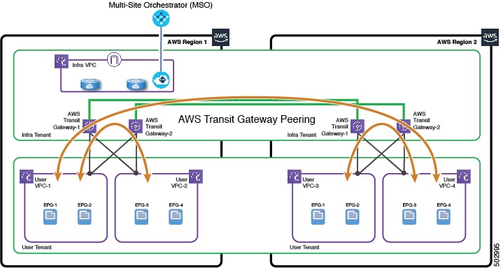
Communication Between VPCs in Different Regions
You can connect Amazon Web Services (AWS) virtual private clouds (VPCs) in different AWS regions using AWS Transit Gateway peering if both regions support Transit Gateway peering. Transit Gateway peering is automatically created by Cisco Cloud Application Policy Infrastructure Controller (APIC) if both regions support peering. All relevant routes are installed on both the source and destination VPCs as well as on AWS Transit Gateways in both regions.
If either of the two regions does not support AWS Transit Gateway peering, the inter-region VPC connectivity will use VPN tunneling. In this case, each of the VPCs that needs to communicate with VPCs in the other region must have an AWS Virtual Gateway (VGW) deployed. Cisco Cloud APIC will then establish VPN tunnels between the VGWs and the CSRs in the infra VPC to connect the VPCs in the different regions to each other. Each region can have its own CSRs deployed, or regions can share the CSRs from another regions.
The following illustrations depict the topologies for common scenarios in which at least one region does not support AWS Transit Gateway peering. In the first example, AWS Region 2 does not have its own CSRs and instead shares the CSRs in AWS Region 1 for inter-region and intersite connectivity.
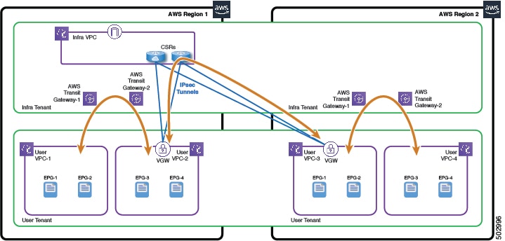
In the second example, each AWS region has its own CSRs.
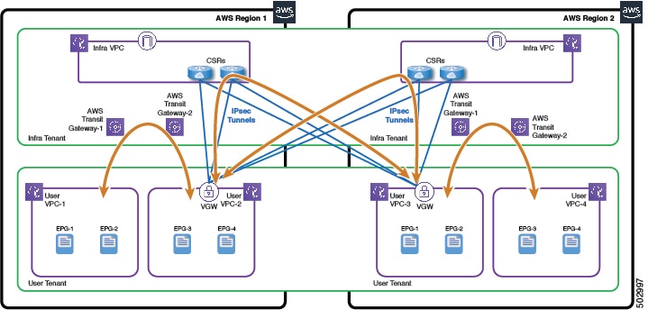
Note |
For both examples, inside each region, inter-VPC communication can still use the regional AWS Transit Gateways. |
Communication Between Cloud and On-Premises Sites
You can connect an Amazon Web Services (AWS) region in an AWS cloud site to an on-premises site using its regional AWS Transit Gateway, provided that the region has Cisco Cisco Cloud Services Routers (CSRs) deployed locally in the infra tenant. The data paths between the user VPCs in this region and the on-premises site will go through the AWS Transit Gateways, CSRs, and the IPsec tunnels between the CSRs and the IPsec VPN devices at the on-premises site.
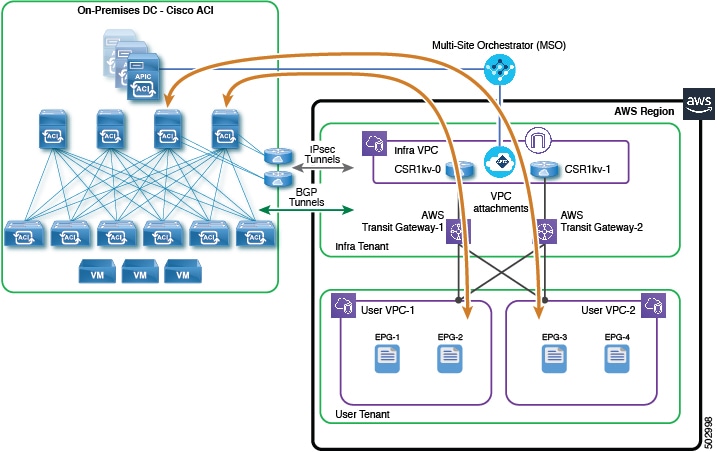
Communication between the cloud site with AWS Transit Gateway sites is similar to when the cloud site does not have the AWS Transit Gateway. In both cases, the cloud site requires a Cisco Cloud Services Router to communicate with the on-premises site.
However, connectivity from the cloud site is from a virtual public cloud (VPC) to the AWS Transit Gateway to the CSR to the on-premises site.
AWS Transit Gateway Limitations and Restrictions
Be aware of the following issues when configuring Amazon Web Services (AWS) Transit Gateways:
-
Overlapping CIDR IP addresses are not allowed within a hub network; however, two different hub networks can have overlapping CIDR IP addresses.
-
Cisco Cloud Application Policy Infrastructure Controller (APIC) automatically creates one route table for each account (tenant) that shares the AWS Transit Gateway. All user VPCs of a given account are automatically associated to that account's route table. Because of the route table restriction of 20, a given AWS Transit Gateway can be shared by no more than 20 different tenants.
-
You cannot use tunnels for VPC-AWS Transit Gateway attachments because of the bandwidth limit of 1.5 Gbs for a connection.
-
AWS Transit Gateways cannot span regions; you must create at least one AWS Transit Gateway in each region and then connect them.
If AWS does not support AWS Transit Gateway peering in any region managed by Cisco Cloud Application Policy Infrastructure Controller (APIC), you need to deploy at least two CSRs in at least one of the managed regions to support inter-region traffic in the cloud only (without inter-site connectivity).
-
You can attach a Cisco Cloud APIC user tenant’s VPC (CtxProfile) to an AWS Transit Gateway (hub network) only if you have administrator privileges and the user is part of security domain “all". Without such access, you cannot attach the user tenant’s VPC to an AWS Transit Gateway.
For information about setting administrator privileges, see the chapter "Cisco Cloud APIC Security" in the Cisco Cloud APIC for AWS User Guide. release 5.0(x) or later.
-
If you want to configure connectivity to on-premises sites, each region must have a CSR deployed in that region.
Prerequisites for Configuring AWS Transit Gateway
You must complete the following tasks before you configure Amazon Web Services (AWS) Transit Gateway:
-
Install Cisco Cloud APIC.
Follow instructions in the Cisco Cloud APIC for AWS Installation Guide, Release 5.0(x).
-
Make sure that your sites—whether on-premises ore in the cloud—are set up correctly.
Follow instructions in the appropriate Cisco Application Policy Infrastructure Controller (APIC) or Cisco Cloud APIC documentation.
-
If you are connecting an on-premises site to a cloud site, configure and deploy your on-premises Cisco Application Centric Infrastructure (ACI) fabric and Cisco ACI Multi-Site. Also ensure that you have a Multi-Site license.
AWS Transit Gateway Configuration Workflow
This section provides an a high-level overview of the tasks you perform to configure Amazon Web Services (AWS) Transit Gateway:
-
Complete the tasks and meet the requirements in the section Prerequisites for Configuring AWS Transit Gateway.
-
Set up the AWS cloud site, following the procedure Set Up the Cloud Site to Use AWS Transit Gateway.
-
Perform the tasks in the chapter "Configuring the Cisco Cloud APIC Using the GUI," in the Cisco Cloud APIC for AWS User Guide 5.0(x).
The tasks include configuring a tenant, an application profile, a VRF, one or more endpoint groups (EPGs), and one or more contracts and filters.
Note
If you plan to configure VPC intersite communication, you can perform these tasks with the Cisco ACI Multi-Site Orchestrator. See the chapter "Day-0 Operations of Cisco ACI Multi-Site Orchestrator" in the Cisco ACI Multi-Site Orchestrator Installation and Upgrade Guide.
-
Create a VRF and deploy it to a particular region, which creates a virtual private cloud (VPC) that can communicate with other VPCs in the same AWS Transit Gateway.
If you create a VRF in Cisco Cloud Application Policy Infrastructure Controller (APIC), you also must create a cloud context profile for each VRF in each region and associate it with the VRF.
-
Verify that AWS Transit Gateway is deployed correctly.
Follow the procedure in the section Verify the AWS Transit Gateway Deployment.
Configuring AWS Transit Gateway
To use an Amazon Web Services (AWS) Transit Gateway, you set up the cloud site and then create a VRF and deploy it to a particular region.
You use Cisco Cloud APIC to set up the cloud site. You can use Cisco Cloud APIC to create a VRF; however, if you are using AWS Transit Gateway in a multisite environment, we recommend that you do so in Cisco Application Centric Infrastructure (ACI) Multi-Site Orchestrator.
Set Up the Cloud Site to Use AWS Transit Gateway
Complete this task to set up the Amazon Web Services (AWS) cloud site. This procedure assumes that you have not yet set up the cloud site.
Before you begin
Procedure
| Step 1 |
Log in to Cisco Cloud APIC. |
||
| Step 2 |
In the Welcome to Cloud APIC dialog box, click Review First Time Setup. |
||
| Step 3 |
In the Let's Configure the Basics dialog box, in the Region Management area, click the blue button. |
||
| Step 4 |
In the Setup—Region Management dialog box, make sure that the Enabled check box under Use Transit Gateway is checked. AWS Transit Gateway is enabled by default. |
||
| Step 5 |
In the Regions to Manage area, choose one or more regions that you want to manage. If you choose AWS Transit Gateway, an AWS Transit Gateway is automatically created for connectivity within a region, and the Cloud Routers check box for the selected region is automatically checked. |
||
| Step 6 |
If you want connectivity to the on-premises site or another cloud site—in addition to connectivity within a region—check the Inter-Site Connectivity check box. |
||
| Step 7 |
If you want to use AWS Transit Gateway statistics, check the TGW Stats check box for one or more regions. Checking the check box enables collection of AWS Transit Gateway traffic statistics for infra tenants for the specified regions.
|
||
| Step 8 |
Click Next. Another panel of the Setup—Region Management dialog box appears. The General area shows the subnets for the cloud routers, which you provided when you installed Cisco Cloud APIC. |
||
| Step 9 |
In the Hub Network area, click Add Hub Network. When you configure a hub network, a pair of AWS Transit Gateways is deployed to a region. |
||
| Step 10 |
In the Name field, enter a name for the hub network. |
||
| Step 11 |
In the BGP Autonomous System Number field, enter a zero for AWS to choose a number, or enter a value between 64512 and 65534, inclusive, for each hub network, and then click the check mark next to the field. To configure your own BGP autonomous number, enter a value between 64512 and 65534 for each hub network. We recommend that you use different numbers for different instances of AWS Transit Gateway. |
||
| Step 12 |
In the CSRs area, in the Password field, enter a password. Entering a password is required, even if you are using AWS Transit Gateway and are not configuring intersite communication. No CSRs will be deployed in such a case. |
||
| Step 13 |
Do one of the following:
|
||
| Step 14 |
In the IPSec Tunnels to Inter-Site Routers area, click Add Public IP of IPSec Tunnel Peer. |
||
| Step 15 |
In the OSPF Area for Inter-Site Connectivity field, enter the IP address of the IPSec tunnel peer. |
||
| Step 16 |
In the External Subnet field, enter the external subnet. |
||
| Step 17 |
Click Save and Continue. |
What to do next
-
Verify the creation of the AWS Transit Gateway route table for the infra tenant.
-
Go to the AWS console, and in the left navigation pane, click Transit Gateway Route Tables.
-
In the central pane, verify that the route table has been created for the AWS Transit gateway, and then click it.
-
In the lower Transit Gateway Route Table pane, click the Routes tab, and then view the information.
-
-
Perform the tasks in the chapter "Configuring the Cisco Cloud APIC Using the GUI," in the Cisco Cloud APIC for AWS User Guide 5.0(x).
The tasks include configuring a tenant, an application profile, a VRF, one or more endpoint groups (EPGs), and one or more contracts and filters.
-
Associate a VRF to a region.
-
If you are configuring communication for virtual private clouds (VPCs) in different sites, follow the procedure Associate a VRF to a Region Using Cisco MSO.
-
If you are not configuring VPC intersite communication, follow the procedure Associate a VRF to a Region Using Cisco Cloud APIC.
-
Associate a VRF to a Region Using Cisco Cloud APIC
After you configure the cloud site, you must associate a VRF to a region. If you are not configuring intersite connectivity, follow the procedure in this section, which makes the association through a cloud context profile.
Note |
If you are configuring intersite connectivity, follow the procedure in the section Associate a VRF to a Region Using Cisco MSO. |
Before you begin
Configure the cloud site, following the procedure Set Up the Cloud Site to Use AWS Transit Gateway.
Procedure
| Step 1 |
Click the Intent icon. The Intent menu appears. |
||||||||||||||||||||||||||||
| Step 2 |
Click the drop-down arrow below the Intent search box and choose Application Management. A list of Application Management options appear in the Intent menu. |
||||||||||||||||||||||||||||
| Step 3 |
From the Application Management list in the Intent menu, click Create Cloud Context Profile. The Create Cloud Context Profile dialog box appears. |
||||||||||||||||||||||||||||
| Step 4 |
Enter the appropriate values in each field as listed in the following Cloud Context Profile Dialog Box Fields table then continue.
|
||||||||||||||||||||||||||||
| Step 5 |
Click Save when finished. |
||||||||||||||||||||||||||||
What to do next
Verify the AWS Transit Gateway deployment. See the section Verify the AWS Transit Gateway Deployment.
Associate a VRF to a Region Using Cisco MSO
After you configure the cloud site, you must associate a VRF to a region. Doing so creates a virtual private cloud (VPC) that can communicate with other VPCs in the same Amazon Web Services (AWS) Transit Gateway. If you are configuring intersite connectivity, follow the procedure in this section, which makes the association using Cisco Multi-Site Orchestrator.
Note |
If you are not configuring intersite connectivity, follow the procedure in the section Associate a VRF to a Region Using Cisco Cloud APIC. |
Before you begin
You must complete the following tasks before you can associate a VRF to a region:
-
Configure infra, a tenant, an application profile, a VRF, one or more endpoint groups (EPGs), and one or more contracts and filters.
You can perform these tasks either in Cisco Cloud APIC or Cisco Application Centric Infrastructure (ACI) Multi-Site Orchestrator:
-
To use Cisco Cloud APIC, see the chapter "Configuring the Cisco Cloud APIC Using the GUI," in the Cisco Cloud APIC for AWS User Guide 5.0(x).
-
To use the Cisco ACI Multi-Site Orchestrator, see the chapter "Day-0 Operations of Cisco ACI Multi-Site Orchestrator" in the Cisco ACI Multi-Site Orchestrator Installation and Upgrade Guide.
-
-
Add sites to the Cisco ACI Multi-Site Orchestrator, following the procedure "Adding Sites Using Multi-Site Orchestrator GUI" in the Cisco ACI Multi-Site Orchestrator Installation and Upgrade Guide.
-
Create a schema in Cisco ACI Multi-Site Orchestrator, following the procedure "Adding Schemas Using Cisco ACI Multi-Site Orchestrator GUI" in the Cisco ACI Multi-Site Orchestrator Installation and Upgrade Guide.
-
Configure the cloud site, following the procedure Set Up the Cloud Site to Use AWS Transit Gateway.
Procedure
| Step 1 |
Log in to the Cisco ACI Multi-Site Orchestrator GUI. |
| Step 2 |
In the left navigation pane, click Schemas. |
| Step 3 |
In the Schemas work pane, choose a schema that you want to deploy, and then in the left navigation pane, click a template in the schema. |
| Step 4 |
In the template work pane, scroll to the VRF area. |
| Step 5 |
Click a VRF. The template and VRF that you choose must be deployed on the cloud site. |
| Step 6 |
In the right properties pane for VRF, click the region that you want to associate the VRF to. |
| Step 7 |
In the Update Cloud Region CIDRs dialog box, complete the following steps: |
| Step 8 |
Click Save. |
| Step 9 |
In the left navigation pane, click the template that you chose in step 3. |
| Step 10 |
Near the top of the central work pane, click Deploy to sites. A VPC is created on the site, and the VRF attachment is made to AWS Transit Gateway.
|
What to do next
Verify the AWS Transit Gateway deployment. See the section Verify the AWS Transit Gateway Deployment.
Verify the AWS Transit Gateway Deployment
After you configure Amazon Web Services (AWS) Transit Gateway, you should verify that it is deployed correctly.
Before you begin
You must have set up the cloud site and created a VRF and deployed it to a particular region.
Procedure
| Step 1 |
Log into Cisco Cloud Application Policy Infrastructure Controller (APIC). |
||
| Step 2 |
In the left navigation pane, choose . The central work pane displays the routers in the AWS cloud. The ones associated with AWS Transit Gateway have TGW in the Type column. |
||
| Step 3 |
Click the number for the router in the VRF column. A slide-out panel appears and displays a list of the associated VRFs. You can see how many VRFs there are and which ones are attached to the AWS Transit Gateway.
|
AWS Transit Gateway Connect with Cisco Cloud APIC
The support for AWS Transit Gateway that was introduced in release 5.0(1) provided a means to connect VPCs or VRFs in the cloud by associating those VPCs or VRFs to the same AWS Transit Gateways. As part of that support, two AWS Transit Gateways are created for each hub network in a region. However, the need to have two AWS Transit Gateways as part of this feature in release 5.0(1) is based on Cisco Cloud APIC requirements and is not an Amazon requirement or recommendation.
Beginning in release 5.2(1), support is now available for the AWS Transit Gateway Connect feature with Cisco Cloud APIC. By using the AWS Transit Gateway Connect feature, only one AWS Transit Gateway is needed for each hub network in a region. Using the AWS Transit Gateway Connect feature also enables equal-cost multi-path (ECMP) routing in a region.
Benefits of Using AWS Transit Gateway Connect with Cisco Cloud APIC
Because AWS Transit Gateway Connect is an extension of the existing AWS Transit Gateway feature, the benefits listed in Benefits of Using AWS Transit Gateway with Cisco Cloud APIC are also applicable for AWS Transit Gateway Connect.
In addition to those benefits, using AWS Transit Gateway Connect with Cisco Cloud APIC provides the following benefit:
Higher performance: AWS Transit Gateway Connect provides significantly more bandwidth than other methods of communication between VPCs. AWS Transit Gateway Connect uses Generic Routing Encapsulation (GRE) tunnels to provide over 100 Gbps bandwidth for each VPC connection, whereas VPN connections over Internet Protocol Security (IPsec) tunnels are limited to 1.5 Gbps and the AWS Transit Gateway feature supported in release 5.0(1) provides up to 50 Gbps bandwidth for each VPC connection.
AWS Transit Gateway Connect Terminology
In addition to the terminology provided in AWS Transit Gateway Terminology, the following terminology and concepts are provided for the AWS Transit Gateway Connect feature:
- AWS Transit Gateway Connect
- The term AWS Transit Gateway Connect collectively refers to the connect VPC (infra VPC) and the transport attachment. This service enables connectivity between the AWS Transit Gateway and the CSRs in a region using GRE tunnels.
- Connect attachment
- A new Transit Gateway attachment that leverages the existing transport attachment used with AWS Transit Gateway. GRE and BGP are supported over the connect attachment.
- Connect VPC
- The infra VPC that is unique to the AWS Transit Gateway Connect feature, where the connect VPC uses a single infra VPC attachment as opposed to the two VPC attachments that are used with the AWS Transit Gateway feature.
- Transport attachment
- Also known as attachment in AWS Transit Gateway Terminology, but shown as transport attachment as part of the AWS Transit Gateway Connect terminology to distinguish it from the connect attachment. The transport attachment is used as the underlying transport by the connect attachment.
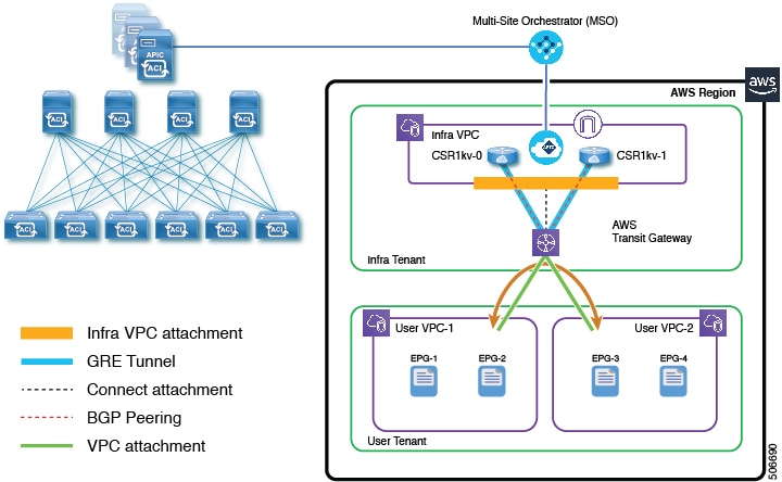
Differences Between Inter-Site Communication With AWS Transit Gateway Peering and AWS Transit Gateway Connect
With release 5.0(1), support was provided for the AWS Transit Gateway peering feature with Cisco Cloud APIC, which enabled communication between VPCs within the same AWS region (inter-site communication) as described in Communication Between VPCs Within an AWS Region.
Beginning with release 5.2(1), the AWS Transit Gateway Connect feature can be used with Cisco Cloud APIC for inter-site communication using a single AWS Transit Gateway, rather than the two AWS Transit Gateways that were required in release 5.0(1).
The following figure shows a configuration using AWS Transit Gateway Connect with a single AWS Transit Gateway (contrasted with a similar configuration with two AWS Transit Gateways shown in Communication Between VPCs Within an AWS Region).
Following are this differences in using Transit Gateway with the connect attachment in release 5.2(1) and Transit Gateway with just the infra VPC attachment in release 5.0(1):
-
Two to four CSRs can be present in the infra VPC, but the number of AWS Transit Gateways connected to those infra VPC is reduced from two to one.
-
The existing infra VPC attachment to the CSRs remains intact but is reduced from two to one.
-
A new connect attachment is used with the infra VPC attachment between the infra VPC and the AWS Transit Gateway as the underlying transport.
-
A GRE tunnel is configured on each CSR to provide the required encapsulation for transparent routing of packets between the AWS Transit Gateway and the CSRs over the connect attachment. This overlay tunneling is required to have the VPC data plane forward traffic reliably between the AWS Transit Gateway and the CSRs.
Inter-Site Communication Using AWS Transit Gateway Connect
The topic Differences Between Inter-Site Communication With AWS Transit Gateway Peering and AWS Transit Gateway Connect provides some information on how inter-site traffic is enabled using AWS Transit Gateway Connect when compared to the AWS Transit Gateway peering feature that was supported with Cisco Cloud APIC in release 5.0(1). Additionally, with AWS Transit Gateway Connect, BGP sessions are established over the GRE tunnels to provide dynamic route updates and health checks. These routes are associated and propagated to the AWS Transit Gateway infra route table, and also to all of the AWS Transit Gateway tenant route tables.
The figure in that topic shows a configuration with two CSRs, where the 0/0 route is advertised by all of the CSRs using this BGP session. These routes reflect in the AWS Transit Gateway route tables pointing to all of the connect peers (the GRE tunnels toward the CSRs) as the next hop. For the route table for that example with two CSRs, two next hops would be configured for the 0/0 route, which would enable the two-way ECMP of all the traffic from the AWS Transit Gateway toward the CSRs.
Similarly, you could have a configuration where four CSRs are deployed in the same region's infra VPC, as shown in the following figure.
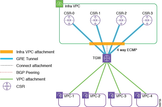
In this configuration, four connect peers are configured (GRE tunnels and BGP sessions). The AWS Transit Gateway route tables will have four next hops for the 0/0 route in this configuration, which enables the four-way ECMP of all the traffic from the AWS Transit Gateways toward the CSRs.
AWS Transit Gateway Connect Limitations and Restrictions
Following are the limitations and restrictions for AWS Transit Gateway Connect:
-
You can have a maximum of four CSRs per region when using AWS Transit Gateway Connect with Cisco Cloud APIC. This is due to a limitation from AWS, where AWS allows for a maximum of four connect peers per connect attachment.
-
At this time, AWS supports the Transit Gateway Connect feature only in the following regions:
-
US East (N. Virginia, Ohio)
-
US West (Oregon, N. California)
-
Europe (Ireland, London, Paris, Frankfurt, Stockholm, Milan)
-
Asia Pacific (Tokyo, Seoul, Singapore, Sydney, Mumbai, Hong Kong, Beijing, Ningxia)
-
Canada (Central)
-
South America (São Paulo)
-
Africa (Cape Town)
-
Middle East (Bahrain)
-
AWS GovCloud (US-East, US-West)
Note
AWS periodically adds support for Transit Gateway Connect in additional regions. For the latest list of regions that support this feature, see the AWS Transit Gateway FAQs.
Because of this limitation, Cisco Cloud APIC supports having a hybrid topology on both inter-site and intra-site configurations, where you can have a mixture of sites with the AWS Transit Gateway Connect feature enabled or disabled. The AWS Transit Gateway Connect feature on the Cisco Cloud APIC is a site local setting, so in a multi-site configuration, you can have one site with the AWS Transit Gateway Connect feature enabled and another site with the AWS Transit Gateway Connect feature disabled.
In a site with multiple hub networks, the hybrid topology can also be between hub networks, where you can have one hub network with the AWS Transit Gateway Connect feature enabled and the other hub network with the AWS Transit Gateway Connect feature disabled.
-
Prerequisites for Configuring AWS Transit Gateway Connect
You must complete the following tasks before you configure Amazon Web Services (AWS) Transit Gateway:
-
Install Cisco Cloud APIC.
Follow instructions in the Cisco Cloud APIC for AWS Installation Guide, Release 5.0(x).
-
Make sure that your sites—whether on-premises or in the cloud—are set up correctly.
Follow instructions in the appropriate Cisco Application Policy Infrastructure Controller (APIC) or Cisco Cloud APIC documentation.
-
If you are connecting an on-premises site to a cloud site, configure and deploy your on-premises Cisco Application Centric Infrastructure (ACI) fabric and Cisco ACI Multi-Site. Also ensure that you have a Multi-Site license.
Configuring AWS Transit Gateway Connect
To use AWS Transit Gateway Connect, you set up the cloud site and then create a VRF and deploy it to a particular region.
Set Up the Cloud Site to Use AWS Transit Gateway Connect
Complete this task to set up the Amazon Web Services (AWS) cloud site. This procedure assumes that you have not yet set up the cloud site.
Before you begin
Procedure
| Step 1 |
Log in to Cisco Cloud APIC. |
||
| Step 2 |
In the Welcome to Cloud APIC dialog box, click Review First Time Setup. |
||
| Step 3 |
In the Let's Configure the Basics dialog box, in the Region Management area, click the blue button. |
||
| Step 4 |
In the Setup—Region Management dialog box, make sure that the Enabled check box under Use Transit Gateway is checked. AWS Transit Gateway is enabled by default. |
||
| Step 5 |
In the Regions to Manage area, choose one or more regions that you want to manage. If you choose AWS Transit Gateway, an AWS Transit Gateway is automatically created for connectivity within a region, and the Cloud Routers check box for the selected region is automatically checked. |
||
| Step 6 |
If you want to use AWS Transit Gateway statistics, check the TGW Stats check box for one or more regions. Checking the check box enables collection of AWS Transit Gateway traffic statistics for infra tenants for the specified regions.
|
||
| Step 7 |
Click Next. Another panel of the Setup—Region Management dialog box appears. The General area shows the subnets for the cloud routers, which you provided when you installed Cisco Cloud APIC. |
||
| Step 8 |
In the Hub Network area, click Add Hub Network. The Add Hub Network window appears. |
||
| Step 9 |
Complete the remaining configurations in this page, if necessary. The remaining configurations are not related to the AWS Transit Gateway Connect feature but are provided here for completeness. |
||
| Step 10 |
Click Save and Continue. |
What to do next
-
Verify the creation of the AWS Transit Gateway Connect attachment.
-
Go to the AWS console, and in the left navigation pane, click Transit Gateway Attachments.
Verify that you see the AWS Transit Gateway Connect attachment in this screen.
-
Select the Transit Gateway Connect attachment.
You can see the connect peers in this window. The number of peers should be equal to the CSRs in this region.
-
In the central pane, verify that the route table has been created for the AWS Transit gateway, and then click it.
-
In the lower Transit Gateway Route Table pane (infra route table), click the Routes tab, and then view the information.
You can find the 0/0 route pointing to the next-hop as connect peers. The number of next-hops will be equal to the number of CSRs in that region.
-
-
Perform the tasks in the chapter "Configuring the Cisco Cloud APIC Using the GUI," in the Cisco Cloud APIC for AWS User Guide 5.0(x).
The tasks include configuring a tenant, an application profile, a VRF, one or more endpoint groups (EPGs), and one or more contracts and filters.
-
Associate a VRF to a region.
Follow the procedures provided in Associate a VRF to a Region Using Cisco Cloud APIC, then return here.
-
Verify that the configurations were set correctly after you have associated a VRF to a region.
-
Go to the AWS console, and in the left navigation pane, click Transit Gateway Route Tables.
-
In the central pane, verify that the route table has been created for the AWS Transit Gateway, and then click it.
-
In the lower Transit Gateway Route Table pane (the tenant route tables), click the Routes tab, and then view the information.
You can find the 0/0 route pointing to the next-hop as connect peers. The number of next-hops will be equal to the number of CSRs in that region.
-
Configure AWS Transit Gateway Connect Using the REST API
This section demonstrates how to configure AWS Transit Gateway Connect through the cloud template using the REST API.
Procedure
|
To configure AWS Transit Gateway Connect through the cloud template: Where the following highlighted areas are specific to configuring AWS Transit Gateway Connect through the cloud template:
|
Verify the AWS Transit Gateway Connect Deployment
After you configure AWS Transit Gateway Connect, you should verify that it is deployed correctly.
Before you begin
You must have set up the cloud site and created a VRF and deployed it to a particular region.
Procedure
| Step 1 |
Verify that the AWS Transit Gateway Connect is deployed correctly through the Cisco Cloud APIC. |
| Step 2 |
Verify that the AWS Transit Gateway Connect is deployed correctly through the AWS portal. |
Transit Gateway External Networking
Beginning with release 25.0(2), several external networking enhancements are available for the AWS transit gateway feature:
-
Deployment modes for the transit gateway route tables
-
External network connectivity with transit gateway
The following sections provide more information on each of these external networking enhancements available beginning in release 25.0(2).
About the Deployment Modes for the Transit Gateway Route Tables
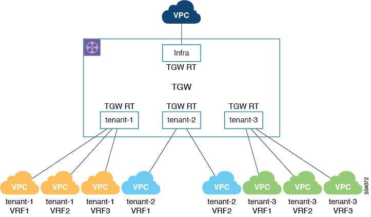
Prior to release 25.0(2), by default, the transit gateway route tables are deployed per tenant. The figure below provides an example of this scenario, where each VPC belonging to a tenant is associated with the respective transit gateway route table that is named after the VPC tenant name.
Beginning with release 25.0(2), Cisco Cloud APIC supports deploying the transit gateway route tables using one of the following modes, where you select one of these supported modes when configuring the cloud context profile:
-
At the network/VRF level: This is the default mode for deploying transit gateway route tables beginning with release 25.0(2). The transit gateway route tables are deployed at the network or VRF level in this mode.
-
At the account/tenant level: This is essentially the method prior to release 25.0(2), where the transit gateway route tables are deployed at the account or tenant level.
-
Using a custom label: The custom label allows you to create a transit gateway route table with the label as its name and to associate a VPC with this transit gateway route table. In this case, you will first add the necessary custom labels in the hub network, then you will choose this type of deployment mode and select the custom label in the cloud context profile.
The following sections provide more information on the three modes used to deploy the transit gateway route tables:
Network/VRF Level
Deploying the transit gateway route tables at the network or VRF level is the default option beginning with release 25.0(2).
In this case, you will set this type of transit gateway route table deployment method through the GUI by selecting the Network Level option, or through the REST API by entering "system=='vrf'" in the label field in the cloudCtxProfileToGatewayRouterP managed object.
The transit gateway route table name is then automatically configured in the cloud using the following format:
<tenantName>-<vrfName>
The following figure shows examples where transit gateway route tables are deployed at the network or VRF level.
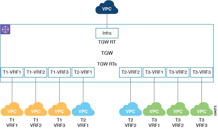
For example, for the three VPCs associated with tenant T1, the transit gateway route tables T1-VRF1, T1-VRF2, and T1-VRF3 are deployed, based on the <tenantName>-<vrfName> format.
Account/Tenant Level
You can also choose to deploy the transit gateway route tables at the account or tenant level. In this case, you will set
this type of transit gateway route table deployment method through the GUI by selecting the Account Level option, or through the REST API by entering "system=='tenant'" in the label field in the cloudCtxProfileToGatewayRouterP managed object.
The transit gateway route table name is then automatically configured in the cloud using the following format:
<tenantName>
This is essentially the same behavior that existed prior to release 25.0(2), where the transit gateway route tables are deployed per tenant.
The following figure shows examples where transit gateway route tables are deployed at the account or tenant level.
For example, for the three VPCs associated with tenant tenant-1, the transit gateway route table named tenant-1 is deployed, based on the <tenantName> format.
Custom Label
The custom label allows you to create a transit gateway route table with the label as its name and to associate a VPC with this transit gateway route table. In this case, you will first add the necessary custom labels in the hub network, then you will choose this type of deployment mode and select the custom label in the cloud context profile in the following manner:
-
If you are setting this type of transit gateway route table deployment method through the GUI, you will select the
Label Basedoption, then you will select a custom label that you added in the hub network. -
If you are setting this type of transit gateway route table deployment method through the REST API, you will enter
"custom==<labelName>"in thelabelfield in thecloudCtxProfileToGatewayRouterPmanaged object, where<labelName>is a custom label that you added in the hub network. You can associate multiple user VPCs to this custom route table by providing the same label in thecloudCtxProfileToGatewayRouterPmanaged object.
The transit gateway route table name is then automatically configured in the cloud using the following format:
custom-<Label>
The following figure shows an example of custom label-based transit gateway route tables.
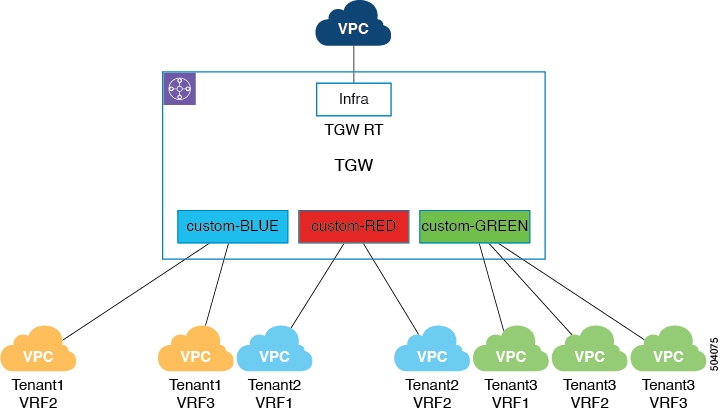
For example, for the three VPCs associated with tenant Tenant3, all three VPCs are associated with the custom label GREEN, which results in the deployment of the transit gateway route table custom-GREEN, based on the custom-<Label> format.
You can also associate multiple user VPCs from different tenant VRF combinations to a custom route table. The following figure shows an example of this type of configuration.
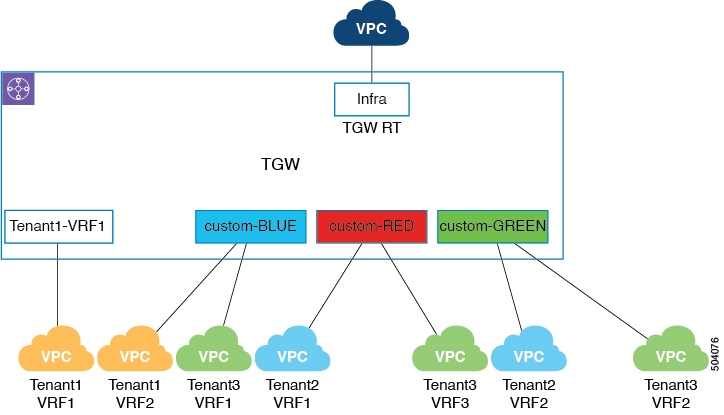
In this example:
-
For the first VPC associated with tenant
Tenant1, the transit gateway route table is deployed at the network or VRF level, which results in the deployment of the transit gateway route tableTenant1-VRF1based on the<tenantName>-<vrfName>format. -
The remaining VPCs are all associated with the custom labels
BLUE,RED, andGREEN, and are deployed based on thecustom-<Label>format.
Guidelines and Limitations
-
If multiple VPCs (cloud context profiles) belong to the same VRF, those multiple VPCs must use the same transit gateway route table mode.
-
When upgrading the Cisco Cloud APIC software, the transit gateway route table deployment mode will be set to the account/tenant level mode to match the existing deployment.
Configuring the Deployment Modes for the Transit Gateway Route Tables Using the GUI
Before you begin
Procedure
| Step 1 |
Add the custom labels in the hub network, if necessary. If you want to use custom labels for the transit gateway route tables as described in Custom Label, you must first add the custom labels in the hub network. |
| Step 2 |
In the Cisco Cloud APIC GUI, navigate to . The list of configured cloud context profiles is displayed. |
| Step 3 |
Click . The Create Cloud Context Profile window is displayed. |
| Step 4 |
Make the appropriate selections and enter the necessary information in the Tenant, Region, VRF, and CIDR fields. |
| Step 5 |
In the TGW Attachment field, click the box next to Enable to enable AWS Transit Gateway for this cloud context profile. When you enable the TGW Attachment option, the TGW Route Table Association Scope field appears. |
| Step 6 |
In the TGW Route Table Association Scope field, choose from one of the following options.
|
| Step 7 |
Complete any additional configurations for this cloud context profile, then click Save when finished. |
Configuring the Deployment Modes for the Transit Gateway Route Tables Using the REST API
Before you begin
Procedure
| Step 1 |
Add the custom labels to the cloud template, if necessary. If you want to use custom labels for the transit gateway route tables as described in Custom Label, you must first add the custom labels in the hub network. For example, to add the custom labels such as those described in Custom Label to the cloud template, enter a post such as the following example: |
| Step 2 |
To configure deployment modes for the transit gateway route tables, enter a post such as the following example: Where:
For example:
|
About External Network Connectivity With Transit Gateway
Prior to release 25.0(2), Cisco Cloud APIC only supports EVPN connectivity from the infra VPC CSRs using the AWS transit gateway. Beginning with release 25.0(2), enhancements are available for external network connectivity where CSRs are optional with transit gateway, where you can have a direct VPN connection between the transit gateway and a remote external device over the internet, where the customer gateway is the remote device. For more information on external network connectivity, see the section "External Network Connectivity" in the Cisco Cloud APIC for AWS User Guide, Release 25.0(x) or later.
Transit gateway external connectivity is achieved by creating a VPN attachment between the transit gateway and the customer gateway. The VPN attachment is nothing but VPN tunnels over the internet between the transit gateway and the customer gateway, where two VPN tunnels are configured for every VPN attachment.
This transit gateway VPN attachment is associated with a transit gateway route table that is named after the VRF name of external network. In this case, the transit gateway route table name would be the name of the external VRF, which is a unique VRF introduced in release 25.0(1) that does not have any presence in the cloud but is associated with one or more external networks. For more information on the external VRF, see the section "External VRF" in the Cisco Cloud APIC for AWS User Guide, Release 25.0(x) or later.
To achieve this type of external connectivity, the following configurations take place:
-
The Cisco Cloud APIC takes care of the following configurations:
-
Creating the transit gateway and transit gateway external route table.
-
Creating the customer gateway (the external remote device) in AWS.
-
Creating the site-to-site VPN connection between the transit gateway and the customer gateway.
-
Associating and propagating the VPN attachment to the transit gateway route tables.
-
-
You configure the IPsec tunnels and BGP sessions on the remote device.
The following figure shows an example of external connectivity using transit gateway.
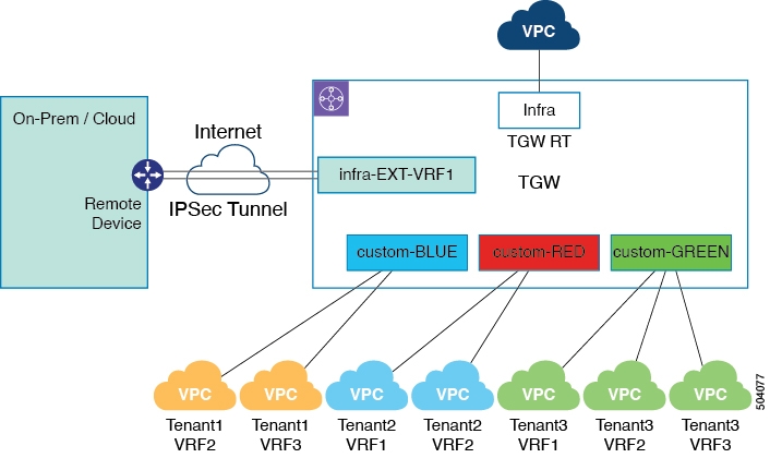
In this example, the external VRF EXT-VRF1 belongs to tenant infra. In this case, Cisco Cloud APIC creates a transit gateway route table named EXT-VRF1 and associates the transit gateway VPN attachment that is created with this route table.
Guidelines and Limitations
Instead of manually selecting all the regions, you have to set allRegion to true for the external network connectivity starting in release 25.0(2).
Configuring External Network Connectivity With Transit Gateway Using the GUI
Before you begin
Review the information in About External Network Connectivity With Transit Gateway before proceeding with these procedures.
Procedure
| Step 1 |
Select TGW as the router type when creating an external network. |
| Step 2 |
Download the external device configuration files. |
Configuring External Network Connectivity With Transit Gateway Using the REST API
Procedure
|
To configure external network connectivity with transit gateway, enter a post such as the following example for the cloud template: Where you must specific the |
Trademarks
THE SPECIFICATIONS AND INFORMATION REGARDING THE PRODUCTS REFERENCED IN THIS DOCUMENTATION ARE SUBJECT TO CHANGE WITHOUT NOTICE. EXCEPT AS MAY OTHERWISE BE AGREED BY CISCO IN WRITING, ALL STATEMENTS, INFORMATION, AND RECOMMENDATIONS IN THIS DOCUMENTATION ARE PRESENTED WITHOUT WARRANTY OF ANY KIND, EXPRESS OR IMPLIED.
The Cisco End User License Agreement and any supplemental license terms govern your use of any Cisco software, including this product documentation, and are located at: http://www.cisco.com/go/softwareterms.Cisco product warranty information is available at http://www.cisco.com/go/warranty. US Federal Communications Commission Notices are found here http://www.cisco.com/c/en/us/products/us-fcc-notice.html.
IN NO EVENT SHALL CISCO OR ITS SUPPLIERS BE LIABLE FOR ANY INDIRECT, SPECIAL, CONSEQUENTIAL, OR INCIDENTAL DAMAGES, INCLUDING, WITHOUT LIMITATION, LOST PROFITS OR LOSS OR DAMAGE TO DATA ARISING OUT OF THE USE OR INABILITY TO USE THIS MANUAL, EVEN IF CISCO OR ITS SUPPLIERS HAVE BEEN ADVISED OF THE POSSIBILITY OF SUCH DAMAGES.
Any products and features described herein as in development or available at a future date remain in varying stages of development and will be offered on a when-and if-available basis. Any such product or feature roadmaps are subject to change at the sole discretion of Cisco and Cisco will have no liability for delay in the delivery or failure to deliver any products or feature roadmap items that may be set forth in this document.
Any Internet Protocol (IP) addresses and phone numbers used in this document are not intended to be actual addresses and phone numbers. Any examples, command display output, network topology diagrams, and other figures included in the document are shown for illustrative purposes only. Any use of actual IP addresses or phone numbers in illustrative content is unintentional and coincidental.
The documentation set for this product strives to use bias-free language. For the purposes of this documentation set, bias-free is defined as language that does not imply discrimination based on age, disability, gender, racial identity, ethnic identity, sexual orientation, socioeconomic status, and intersectionality. Exceptions may be present in the documentation due to language that is hardcoded in the user interfaces of the product software, language used based on RFP documentation, or language that is used by a referenced third-party product.
Cisco and the Cisco logo are trademarks or registered trademarks of Cisco and/or its affiliates in the U.S. and other countries. To view a list of Cisco trademarks, go to this URL: www.cisco.com go trademarks. Third-party trademarks mentioned are the property of their respective owners. The use of the word partner does not imply a partnership relationship between Cisco and any other company. (1721R)
 Feedback