Administrative Operations

Viewing Site Status

You can use the Multi-Site Orchestrator GUI's Dashboard view to see each site's status, number and types of faults, and schema health.

In the SITE STATUS panel, the following fields are displayed on the dashboard:

  • SITE NAME

  • CRITICAL Alarms

  • MAJOR Alarms

  • MINOR Alarms

  • WARNING Alarms

Viewing Schema Health

Using the schema health functionality in the Multi-Site Orchestrator GUI dashboard, you can view the health of the individual schemas that are associated with different sites. In the Schema Details window, you can view the policy types that are associated with each site.

You can perform the following tasks using the SCHEMA HEALTH chart in the GUI:

  • View the aggregated health score of the entire Multi-Site fabric and all APICs

  • View the aggregated fault counts and the fault types for each schema in the Schema Details window

  • View the health of the inter-site schemas

  • View the health of the multi-sites nodes and their components

  • View the health of the connected APICs and ACI clusters

You can view the schema health in the GUI using the following different formats:

  • Hovering on an Individual Cell: Each cell in the SCHEMA HEALTH chart represents the health of the schema. If the cell is color coded as Green and if you hover on the cell, it displays the application health score of the schema.

  • Clicking in the Cell: If you click the individual cell in the table, it provides the additional schema details for the template and the faults with the associated with each policy type, for example, ANP, EPG, Contract, VRF, and BD.

    The faults and warnings are displayed in the columns to the right side of each policy. This functionality is used to collect the details and get more information on the issues causing low health.

  • Viewing the Health Score Slider: The health score slider at the top of the page provides capabilities to filter the schemas by the minimum or maximum health score. A range in the slider can be adjusted to view the schemas that match the heath score range. For example, you can adjust the health score to display the schemas matching the health score between 0 to 30 range.

  • Using the Search Functionality: The search functionality in the schema health view provides the capabilities to find a schema or a policy based on the keywords that are typed in the search area. When the keywords are typed in the search area, only schemas that contain the keywords are displayed. The results are based on the matching keywords as part of the schema name, template name, or any of the contained policies within that schema.

Viewing Faults for Individual Sites

This section describes how to display the faults for the individual sites using the Multi-Site GUI.

Procedure


Step 1

Log in to Multi-Site Orchestrator GUI.

Step 2

In the Main Menu, click Sites.

Step 3

In the Sites list page, click CONFIGURE INFRA.

Step 4

In the Fabric Connectivity Infra page, click the appropriate site in the Master List. For example, click site1.

The site details with the associated pods and the spines are displayed in the GUI.

The total number of the faults and the fault types, for example, Critical, Major, Minor, and Warning faults are displayed at the top of the panel. Clicking on each fault type displays the fault details with the individual codes and their explanations.


DHCP Relay Policy

Typically, when your DHCP server is located under an EPG, all the endpoints in that EPG have access to it and can obtain the IP addresses via DHCP. However, in many deployment scenarios, the DHCP server may not exist in the same EPG, BD, or VRF as all the clients that require it. In these cases a DHCP relay can be configured to allow endpoints in one EPG to obtain IP addresses via DHCP from a server that is located in another EPG/BD deployed in a different site or even connected externally to the fabric and reachable via an L3Out connection.

You can create the DHCP Relay policy in the Orchestrator GUI to configure the relay. Additionally, you can choose to create a DHCP Option policy to configure additional options you can use with the relay policy to provide specific configuration details. For all available DHCP options refer to RFC 2132.

When creating a DHCP relay policy, you specify an EPG (for example, epg1) or external EPG (for example, ext-epg1) where the DHCP server resides. After you create the DHCP policy, you associate it with a bridge domain, which in turn is associated with another EPG (for example, epg2) allowing the endpoints in that EPG to reach the DHCP server. Finally, you create a contract between the relay EPG (epg1 or ext-epg1) and application EPG (epg2) to allow communication. The DHCP policies you create are pushed to the APIC when the bridge domain to which the policy is associated is deployed to a site.

Guidelines and Limitations

The DHCP relay policies are supported with the following caveats:
  • DHCP relay policies are supported for fabrics running Cisco APIC Release 4.2(1) or later.

  • The DHCP servers must support DHCP Relay Agent Information Option (Option 82).

    When an ACI fabric acts as a DHCP relay, it inserts the DHCP Relay Agent Information Option in DHCP requests that it proxies on behalf of clients. If a response (DHCP offer) comes back from a DHCP server without Option 82, it is silently dropped by the fabric.

  • DHCP relay policies are supported in user tenants or the common tenant only. DHCP policies are not supported for the infra or mgmt tenants.

    When configuring shared resources and services in the ACI fabric, we recommend creating those resources in the common tenant, that way they can be used by any user tenant.

  • DHCP relay server must be in the same user tenant as the DHCP clients or in the common tenant.

    The server and the clients cannot be in different user tenants.

  • DHCP relay policies can be configured for the primary SVI interface only.

    If the bridge domain to which you assign a relay policy contains multiple subnets, the first subnet you add becomes the primary IP address on the SVI interface, while additional subnets are configured as secondary IP addresses. In certain scenarios, such as importing a configuration with a bridge domain with multiple subnets, the primary address on the SVI may change to one of the secondary addresses, which would break the DHCP relay for that bridge domain.

    You can use the show ip interface vrf all command to verify IP address assignments for the SVI interfaces.

  • If you make changes to the DHCP policy after you have assigned it to a bridge domain and deployed the bridge domain to one or more sites, you will need to re-deploy the bridge domain for the DHCP policy changes to be updated on each site's APIC.

  • For inter-VRF DHCP relay with the DHCP server reachable via an L3Out, DHCP relay packets must use site-local L3Out to reach the DHCP server. Packets using an L3Out in a different site (Intersite L3Out) to reach the DHCP server is not supported.

  • The following DHCP relay configurations are not supported:

    • DHCP relay clients behind an L3Out.

    • Importing existing DHCP policies from APIC.

    • DHCP relay policy configuration in Global Fabric Access Policies is not supported

    • Multiple DHCP servers within the same DHCP relay policy and EPG.

      If you configure multiple providers under the same DHCP relay policy, they must be in different EPGs or external EPGs.

Creating DHCP Relay Policies

This section describes how to create a DHCP relay policy.


Note

If you make changes to the DHCP policy after you have assigned it to a bridge domain and deployed the bridge domain to one or more sites, you will need to re-deploy the bridge domain for the DHCP policy changes to update on each site's APIC.


Before you begin

You must have the following:
  • A DHCP server set up and configured in your environment.

  • If the DHCP server is part of an application EPG, that EPG must be already created in the Multi-Site Orchestrator, as described in the Schema Management chapter.

    If the DHCP server is external to the fabric, the external EPG associated to the L3Out that is used to access the DHCP server must be already created, as described in the Schema Management chapter.

Procedure


Step 1

Log in to your Multi-Site Orchestrator GUI.

Step 2

From the left navigation menu, select Policies.

Step 3

In the top right of the main pane, click Add Policy and select DHCP.

This opens an Add DHCP configuration screen.

Step 4

In the Name field, specify the name for the policy.

Step 5

From the Select Tenant dropdown, select the tenant that contains the DHCP server.

Step 6

(Optional) In the Description field, provide a description for the policy.

Step 7

Select Relay for the Type.

Step 8

Click +Provider.

Step 9

Select the provider type.

When adding a relay policy, you can choose one of the following two types:

  • Application EPG—specifies a specific application EPG that includes the DHCP server you are adding as an endpoint.

  • L3 External Network—specifies the External EPG associated to the L3Out that is used to access the DHCP server.

Note 

You can select any EPG or external EPG that has been created in the Orchestrator and assigned to the tenant you specified, even if you have not yet deployed it to sites. If you select an EPG that hasn't been deployed, you can still complete the DHCP relay configuration, but you will need to deploy the EPG before the relay is available for use.

Step 10

From the dropdown menu, pick the EPG or external EPG.

Step 11

In the DHCP Server Address field, provide the IP address of the DHCP server.

Step 12

Click Save to add the provider.

Step 13

(Optional) Add any additional providers.

Repeat steps 9 through 12 for each additional DHCP server.

Step 14

Click Save to save the DHCP relay policy.


Creating DHCP Option Policies

This section describes how to create a DHCP option policy. DHCP options are appended to the end of the messages that DHCP servers and clients exchange and can be used to provide additional configuration information to your DHCP server. Each DHCP option has a specific code that you must provide when adding the option policy. For a complete list of DHCP options and codes, see RFC 2132.

Before you begin

You must have the following already configured:
  • A DHCP server set up and configured in your environment.

  • An EPG that contains the DHCP server already created in the Multi-Site Orchestrator, as described in the Schema Management chapter.

  • A DHCP Relay policy created, as described in Creating DHCP Relay Policies.

Procedure


Step 1

Log in to your Multi-Site Orchestrator GUI.

Step 2

From the left navigation menu, select Policies.

Step 3

In the top right of the main pane, click Add Policy and select DHCP.

This opens an Add DHCP configuration screen.

Step 4

In the Name field, specify the name for the policy.

This is a name for the policy you're creating, not a specific DHCP option name. Each policy can contain multiple DHCP options.

Step 5

From the Select Tenant dropdown, select the tenant that contains the DHCP server.

Step 6

(Optional) In the Description field, provide a description for the policy.

Step 7

Select Option for the Type.

Step 8

Click +Option.

Step 9

Specify a name of the option.

While not technically required, we recommend using the same name for the option as listed in RFC 2132.

For example, Name Server.

Step 10

Specify an ID for the option .

You must provide the option code as listed in RFC 2132.

For example, 5 for Name Server option.

Step 11

Specify the option's data.

Provide the value if the option requires one.

For example, a list of name servers available to the client for the Name Server option.

Step 12

Click the check mark next to the Data field to save the option.

Step 13

(Optional) Repeat the steps to add any additional options.

Step 14

Click Save to save the DHCP option policy.


Assigning DHCP Policies

This section describes how to assign a DHCP policy to a bridge domain.


Note

If you make changes to the DHCP policy after you have assigned it to a bridge domain and deployed the bridge domain to one or more sites, you will need to re-deploy the bridge domain it for the DHCP policy changes to be updated on each site's APIC.


Before you begin

You must have the following already configured:

Procedure


Step 1

Log in to your Multi-Site Orchestrator GUI.

Step 2

From the left navigation menu, select Schemas.

Step 3

Select the schema where the bridge domain is defined.

Step 4

Scroll down to the Bridge Domain area and select the bridge domain.

Step 5

In the right sidebar, scroll down and check the DHCP Policy option checkbox.

Step 6

From the DHCP Relay Policy dropdown, select the DHCP policy you want to assign to this BD.

Step 7

(Optional) From the DHCP Option Policy dropdown, select the option policy.

A DHCP option policy provides additional options to be passed to the DHCP relay. For additional details see Creating DHCP Option Policies.

Step 8

Assign the bridge domain to any EPG that needs access to the DHCP server via the relay.


Creating DHCP Relay Contract

DHCP packets are not filtered by contracts but contracts are required in many cases to propagate routing information within the VRF and across VRFs. Even though the DHCP packets are not filtered it is recommended to configure contracts between the client EPG and the EPG configured as the provider in the DHCP relay policy.

This section describes how to create a contract between the EPG that contains the DHCP server and the EPG that contains endpoints that need to use the relay. Even though you have already created and assigned the DHCP policy to the bridge domain and the bridge domain to the clients' EPG, you must create and assign the contract to enable programming of routes to allow client to server communication.

Before you begin

You must have the following already configured:

Procedure


Step 1

Log in to your Multi-Site Orchestrator GUI.

Step 2

From the left navigation menu, select Schemas.

Step 3

Select the schema where you want to create the contract.

Step 4

Create a contract.

DHCP packets are not filtered by the contract so no specific filter is required, but a valid contract should be created and assigned to ensure proper BD and routes deployment.

  1. Scroll down to the Contracts area and click + to create a contract.

  2. In the right sidebar, provide the Display Name for the contract.

  3. From the Scope dropdown, select the appropriate scope.

    Because the DHCP server EPG and application EPG must be in the same tenant, you can select one of the following:

    • vrf, if both EPGs are in the same VRF

    • tenant, if the EPGs are in different VRFs

  4. You can leave the Apply Both Directions knob on.

Step 5

Assign the contract to the DHCP relay EPG.

  1. Browse to the template where the EPG is located.

  2. Select the EPG or external EPG where the DHCP server resides.

    This is the same EPG you selected when creating the DHCP relay policy.

  3. In the right sidebar, click +Contract.

  4. Select the contract you created and provider for its type.

Step 6

Assign the contract to the application EPG whose endpoints require DHCP relay access.

  1. Browse to the template where the application EPG is located.

  2. Select the application EPG.

  3. In the right sidebar, click +Contract.

  4. Select the contract you created and consumer for its type.


Verifying DHCP Relay Policies in APIC

This section describes how to verify that the DHCP relay policies you have created and deployed using the Multi-Site Orchestrator are correctly pushed to each site's APIC. The DHCP policies you create are pushed to the APIC when the bridge domain to which the policy is associated is deployed to a site.

Procedure


Step 1

Log in to the site's APIC GUI.

Step 2

From the top navigation bar, select Tenants > <tenant-name>.

Select the tenant where you deployed the DHCP policy.

Step 3

Verify that the DHCP relay policy is configured in APIC.

In the left tree view, navigate to <tenant-name> > Policies > Protocol > DHCP > Relay Policies. Then confirm that the DHCP relay policy you configured has been created.

Step 4

Verify that the DHCP option policy is configured in APIC.

If you have not configured any DHCP option policies, you can skip this step.

In the left tree view, navigate to <tenant-name> > Policies > Protocol > DHCP > Option Policies. Then confirm that the DHCP option policy you configured has been created.

Step 5

Verify that the DHCP policy is correctly associated with the bridge domain.

In the left tree view, navigate to <tenant-name> > Networking > Bridge Domains > <bridge-domain-name> > DHCP Relay Labels. Verify that the DHCP policy is also associated with the deployed bridge domain.


Editing or Deleting Existing DHCP Policies

This section describes how to edit or delete a DHCP relay or option policy.


Note

  • If you make changes to the DHCP policy after you have assigned it to a bridge domain and deployed the bridge domain to one or more sites, you will need to re-deploy it for the DHCP policy changes to update on each site's APIC.

  • You cannot deleted policies that are associated with one or more bridge domains, you must first unassign the policy from every bridge domain.


Procedure


Step 1

Log in to your Multi-Site Orchestrator GUI.

Step 2

From the left navigation menu, select Policies.

Step 3

Click the actions menu next to the DHCP policy and select Edit or Delete.


System Logs

Multi-Site Orchestrator system logging is automatically enabled when you first deploy the Orchestrator cluster and captures the events and faults that occur in the environment.

You can view the Multi-Site Orchestrator logs by selecting Admin > Audit Logs from the main navigation menu.

From the Audit Logs page, you can click the Most Recent field to select a specific time period for which you want to see the logs. For example, when you select the range from November 14, 2019 to November 17, 2019 and click Apply, the audit log details for this time period are displayed on the Audit Logs page.

You can also click the Filter icon to filter the log details using the following criteria:

  • User: Select this option to filter the audit logs by the user type, then click Apply to apply the filter.

  • Type: Select this option to filter the audit logs by the policy types, for example, site, user, template, application profile, bridge domain, EPG, external EPG, filter, VRF, BGP config, contract, OSPF policy, pod, node, port, domain, provider, RADIUS, TACACS+ and click Apply.

  • Action: Select this option to filter the audit logs by an action. The available actions are Created, Updated, Deleted, Added, Removed, Associated, Disassociated, Deployed, Undeployed, Downloaded, Uploaded, Restored, Logged in, Logged Out, Login Failed. Select an action and click Apply to filter the log details according to the action.

Generating Troubleshooting Report and Logs

This section describes how to generate a troubleshooting report and infrastructure logs file for all the schemas, sites, tenants, and users that are managed by Cisco ACI Multi-Site Orchestrator.

Procedure


Step 1

Log in to your Multi-Site Orchestrator GUI.

Step 2

In the top right corner, click the Options icon and select System Logs.

Step 3

Check the logs you want to download.

Check the Database Backup to download a backup of the Orchestrator database.

Check the Server Logs to download the Orchestrator logs.

Step 4

Click DOWNLOAD.

An archive of the selected items will be downloaded to your system. The report contains the following information:

  • All schemas in JSON format

  • All sites definitions in JSON format

  • All tenants definitions in JSON format

  • All users definitions in JSON format

  • All logs of the containers in the infra_logs.txt file


Enabling Log Streaming to an External Log Analyzer

Cisco ACI Multi-Site Orchestrator allows you to send the Orchestrator logs to an external log analyzer tool in real time. By streaming any events as they are generated, you can use the additional tools to quickly parse, view, and respond to important events without a delay.

This section describes how to enable Multi-Site Orchestrator to stream its logs to an external analyzer tool, such as Splunk.

Before you begin

  • Set up and configure the log analyzer service provider.

    For detailed instructions on how to configure an external log analyzer, consult its documentation.


    Note

    This release of Cisco ACI Multi-Site Orchestrator only supports Splunk as the service provider.


  • Obtain an authentication token for the service provider.

    Obtaining an authentication token for Splunk service is detailed in the Splunk documentation, but in short, you can get the authentication token by logging into the Splunk server, selecting Settings > Data Inputs > HTTP Event Collector, and clicking New Token.

Procedure


Step 1

Log in to your Multi-Site Orchestrator GUI.

Step 2

In the top right corner, click the Options icon and select System Logs.

Step 3

In the System Logs window that opens, enable the EXTERNAL STREAMING knob.

Step 4

Select which logs you want to stream.

You can select either all logs or audit logs only.

Step 5

From the SELECT SERVICE dropdown menu, select the log analyzer service.

This release of Cisco ACI Multi-Site Orchestrator supports only Splunk as the service provider.

Step 6

Choose the PROTOCOL for the traffic.

Select UNSECURE for HTTP or SECURE for HTTPS.

Step 7

Provide the service's information.

In the HOST field, enter the host's IP address.

In the PORT field, enter the host's port number.

In the TOKEN field, enter the authentication token you obtain from the service provider.

Step 8

For each Multi-Site Orchestrator node, provide the node's root password.

Note 

This is the root user password of each Orchestrator node, not the password you use to log in to the Orchestrator GUI.

Step 9

Click OK to save the changes.


Configuration Backup and Restore

You can create backups of your Multi-Site Orchestrator configuration that can facilitate in recovery from Orchestrator failures or cluster restarts. We recommend creating a backup of the configuration before every upgrade or downgrade of your Orchestrator and after every configuration change or deployment. We also recommend exporting the backups to an external storage outside of the Orchestrator nodes' VMs.


Note

Restoring a backup action restores the database on the Multi-Site Orchestrator, but it does not make any changes to the APIC databases on each site. Therefore, after you restore the Orchestrator database, you must also re-deploy any existing schemas to avoid potentially mismatching policies between the Orchestrator and APIC sites. For information on specific configuration mismatch scenarios and backup restore procedures related to each one, see Backup and Restore Guidelines


Backup and Restore Guidelines

When saving and restoring configuration backups, the following guidelines apply:

  • When saving a backup, the configuration is saved in the same state in which it was deployed. When restoring a backup, any policies that were deployed will show as "deployed", while any policies that were not deployed will remain in the "undeployed" state.

  • Restoring a backup action restores the database on the Multi-Site Orchestrator, but it does not make any changes to the APIC databases on each site. As such, certain precautions and steps must be taken when restoring a previous configuration to avoid potentially mismatching policies between the Orchestrator and the APIC sites, as described below.

No Configuration Changes Since Backup

If there have been no policy changes between when the backup was created and when it is being restored, no additional considerations are required and you can simply restore the configuration as described in Restoring Backups.

Objects or Policies Created, Modified, or Deleted Since Backup

If any configuration changes took place between the time when the configuration backup was created and the time it is being restored, consider the following:

  • Restoring a backup will not modify any objects or policies on the APIC sites. Any new objects or policies created and deployed since the backup will remain deployed. You will need to manually remove these after restoring the backup to avoid any stale configurations.

    Alternatively, you can choose to undeploy all policies first, which will avoid any potential stale objects after the configuration is restored from backup. However, this would cause a disruption in traffic or services defined by those policies.

  • The steps required to restore a configuration backup are described in Restoring Backups.

  • If the configuration backup you restored was saved before it was deployed to the APIC sites, it will be restored in the "undeployed" state and you can simply deploy it to the APIC sites as necessary.

  • If the configuration backup you restored was saved when the configuration was already deployed, it will be restored in the "deployed" state, even though none of the policies will exist in the APIC sites yet. In this case, in order for the configuration to be properly pushed to each site, you will need to make a minor configuration change and re-deploy it to sync the Orchestrator's configuration with the APIC sites.

Remote Backups

Cisco ACI Multi-Site is deployed as a 3-node cluster. When you first deploy the cluster, any backups you create are saved to a default location which is located on each node's local disk in the /opt/cisco/msc/backups/ directory.

While the backups are available on any one node and can be viewed using the Orchestrator GUI, we recommend exporting all backups to a remote location outside the Orchestrator VMs. There are two approaches to configuring remote locations for all Orchestrator backups:

  • Configuring a remote NFS share and mounting it to the default backups directory on each node, in which case the backup files are written directly to the remote NFS share bypassing the Orchestrator VMs' local drives.

    This approach is less flexible in that it allows only a single remote location to be used for all configuration backups created from the Orchestrator GUI.

  • Configuring a remote SCP or SFTP location using the Orchestrator GUI and then exporting the backup files there.

    Unlike the remote NFS share approach, configuring one or more remote locations in the Orchestrator GUI allows you to specify multiple destinations and provides additional flexibility for where the backup files can be stored.


    Note

    When you create a configuration backup and export it to a remote server, the files are first created on the Orchestrators' local drives, then uploaded to the remote location, and finally deleted from the local storage. There is a limit on the local backups disk space usage, which if reached can prevent remote backups from being created.


Configuring a Remote Location for Backups

This section describes how to configure a remote location in Multi-Site Orchestrator to which you can then export your configuration backups.

Procedure

Step 1

Log in to your Cisco ACI Multi-Site Orchestrator.

Step 2

From the left navigation pane, select Admin > Remote Locations.

Step 3

In the top right of the main window, click Add Remote Location.

An Add New Remote Location screen appears.

Step 4

Provide the name for the location and an optional description.

Two protocols are currently supported for remote export of configuration backups:

  • SCP

  • SFTP

Step 5

Specify the host name or IP address of the remote server.

Based on your Protocol selection, the server you specify must allow SCP or SFTP connections.

Step 6

Provide the full path to a directory on the remote server where you will save the backups.

The path must start with a slash (/) characters and must not contain periods (.) or backslashes (\). For example, /backups/multisite.

Note 

The directory must already exist on the remote server.

Step 7

Specify the port used to connect to the remote server.

By default, port is set to 22.

Step 8

Specify the authentication type used when connecting to the remote server.

You can configure one of the following two authentication methods:

  • Password—provide the username and password used to log in to the remote server.

  • SSH Private Files—provide the username and the SSH Key/Passphrase pair used to log in to the remote server.

Step 9

Click Save to add the remote server.


Moving Existing Backups to a Remote Location

This section describes how to move an existing configuration backup you have created in the Multi-Site Orchestrator GUI from the nodes' local drives to a remote location.

Before you begin

You must have completed the following:

Procedure

Step 1

Log in to your Cisco ACI Multi-Site Orchestrator.

Step 2

From the left navigation pane, select Admin > Backups.

Step 3

Locate the backup you want to export, then click the actions () icon next to it, then click Move to remote location.

A Move Backup To Remote Location window opens.

Step 4

From the Remote Location dropdown menu, select the remote location.

Step 5

(Optional) Update the remote location path.

The target directory on the remote server, which you configured when creating the remote backup location, will be displayed in the Remote Path field.

You can choose to append additional subdirectories to the path. However, the directories must be under the default configured path and must have been already created on the remote server.


Adding an NFS Share to Store Backups

This section describes how to add an NFS share to the Multi-Site Orchestrator VMs to store configuration backups.


Note

While you can configure a single remote NFS share for your configuration backups, we recommend using the remote backup location feature available in the Orchestrator GUI and described in Configuring a Remote Location for Backups instead.


Procedure

Step 1

Log in directly to your Multi-Site Orchestrator node's VM as the root user.

Step 2

Mount the NFS share.

The following command mounts the shared NFS directory to the default Orchestrator backups folder so all future backups are automatically stored to an external storage outside the Orchestrator VMs.

Note 

If you have any existing backups in this default directory that you want to save, you must manually move them to a different location before mounting the NFS share. After the share is mounted, any existing files in the mount directory will be hidden from view.

# mount <nfs-server-ip>:/<nfs-share-path> /opt/cisco/msc/backups/
Step 3

Repeat steps 1 through 2 on each Orchestrator VM.

Because each Orchestrator node can create and store its own backup files, you must mount the same NFS share on all nodes.

Step 4

Update the Docker backup services.

You must run the following Docker update command for the newly mounted file system to be usable by the Orchestrator services. However, since the command updates the services across the cluster, you only need to do this once after mounting the shares on each node.

# docker service update msc_backupservice --force

What to do next
If at any point you want to remove the NFS share and go back to storing the backups locally on each VM, simply unmount the directory on each node and run the docker service update msc_backupservice --force command again.

Creating Backups

This section describes how to create a new backup of your Multi-Site Orchestrator configuration.

Before you begin

If you want to create the backup using a remote location, you must first add the remote location as described in Configuring a Remote Location for Backups.

Procedure


Step 1

Log in to your Cisco ACI Multi-Site Orchestrator.

Step 2

From the left navigation pane, select Admin > Backups.

Step 3

In the main window, click New Backup.

A New Backup window opens.

Step 4

In the Name field, provide the name for the backup file.

The name can contain up to 10 alphanumeric characters, but no spaces or underscores (_).

Step 5

(Optional) In the Notes field, enter any additional information to describe the backup.

Step 6

Choose the Backup Location.

You can save the backup file locally on the Orchestrator nodes or export it to a remote location.

If you want to save the backup file locally, choose Local.

Otherwise, if you want to save the backup file to a remote location, choose Remote and provide the following:

  • From the Remote Location dropdown menu, select the remote location.

  • In the Remote Path, either leave the default target directory or you can choose to append additional subdirectories to the path. However, the directories must be under the default configured path and must have been already created on the remote server.

Step 7

Click Save to create the backup.


Restoring Backups

This section describes how to restore a Multi-Site Orchestrator configuration to a previous state.

Before you begin

Restoring a backup action restores the database on the Multi-Site Orchestrator, but it does not make any changes to the APIC databases on each site. Therefore, after you restore the Orchestrator database, you must also re-deploy any existing schemas to avoid potentially mismatching policies between the Orchestrator and APIC sites.

For information on specific configuration mismatch scenarios and recommended restore procedures related to each one, see Backup and Restore Guidelines.

Procedure


Step 1

Log in to your Multi-Site Orchestrator GUI.

Step 2

If necessary, undeploy existing policies.

We recommend you perform this step if new objects or policies were added to the configuration between when the backup was created and current configuration. Additional context is available in Backup and Restore Guidelines.
Step 3

From the left navigation menu, select Admin > Backups.

Step 4

In the main window, click the actions () icon next to the backup you want to restore and select Rollback to this backup.

If the version of the selected backup is different from the running Multi-Site version, the rollback could cause a removal of the features that are not present in the backup version.

Step 5

Click Yes to confirm that you want to restore the backup you selected.

If you click Yes, the system terminates the current session and the user is logged out.

Step 6

If necessary, redeploy the configuration.

We recommend you perform this step to sync the restored configuration with the APIC sites. Additional context is available in Backup and Restore Guidelines.

Downloading Backups

This section describes how to download you backup from the Multi-Site Orchestrator.

Before you begin

Procedure


Step 1

Log in to your Multi-Site Orchestrator GUI.

Step 2

From the left navigation menu, select Admin > Backups.

Step 3

In the main window, click the actions () icon next to the backup you want to download and select Download.

This will download the backup file in msc-backups-<timestamp>.tar.gz format to your system. You can then extract the file to view its contents.


Importing Backups

This section describes how to import an existing backup into your Multi-Site Orchestrator.

Before you begin

Procedure


Step 1

Log in to your Multi-Site Orchestrator GUI.

Step 2

From the left navigation menu, select Admin > Backups.

Step 3

In the main window, click Import.

Step 4

In the Import from file window that opens, click Select File and choose the backup file you want to import.

Importing a backup will add it to the list of the backups displayed the Backups page.


Custom SSL Certificates

Cisco ACI Multi-Site Orchestrator OVA contains a self-signed SSL certificate that is stored in /data/msc/secrets directory on each node during the Orchestrator installation. By default, the Orchestrator GUI uses this certificate for its HTTPS connections.

While you could previously update these certificates by logging directly into an Orchestrator node server and changing its web server (nginx) configuration, starting with Cisco ACI Multi-Site Orchestrator Release 2.1(1), you can use the GUI to easily add or update custom certificates to be used for the Orchestrator's GUI connection.

When adding custom certificates, you can use one of the following two options:

  • Self-Signed Certificate provide you with the ability to create your own public and private keys to be used by the Orchestrator's GUI.

  • CA-Issued Certificate allows you to use a certificate provided by an existing Certificate Authority (CA) along with its keys.

You can add multiple CAs and Keyrings containing the public/private key combinations in the GUI, however only a single keyring can be active at any given time and used to secure the communication between the Orchestrator GUI and your browser.

Adding Custom Certificate Authority

You can add a custom Certificate Authority (CA) to be used for verifying the public key provided by the Orchestrator for HTTPS traffic encryption.

This section describes how to add and configure a custom CA in Multi-Site Orchestrator GUI. Configuring keyrings and keys is described in the next section.

Procedure


Step 1

Log in to your Multi-Site Orchestrator GUI.

Step 2

From the left navigation menu, select Admin > Security.

Step 3

In the main window, select the Certificate Authority tab and click Add Certificate Authority.

Step 4

In the Add Certificate Authority window that opens, provide the CA details.

In the Name field, enter the CA name.

In the Description field, enter the CA description.

In the Certificate Chain field, enter the CA's certificate chain. You must include both, intermediate and root, certificates. The intermediate certificate must be entered first, followed by the root certificate.

Step 5

Click SAVE to save the changes.


Adding Custom Keyring

You can add a custom keyring containing a public and private encryption keys to be used for Orchestrator GUI HTTPS traffic encryption.

This section describes how to add a custom keyring. For instructions on adding a Certificate Authority (CA) that can be used to verify the public key in this keyring, see the previous section.

Procedure


Step 1

Log in to your Multi-Site Orchestrator GUI.

Step 2

From the left-hand navigation menu, select Admin > Security.

Step 3

In the main window, select the Key Rings tab and click ADD KEY RING.

Step 4

In the Create Key Ring window that opens, provide the key ring details.

From the SELECT CERTIFICATE AUTHORITY dropdown menu, select the certificate authority that will contain the key ring.

In the NAME field, enter the key ring name.

In the KEY RING DESCRIPTION field, enter the key ring description.

In the PUBLIC KEY field, enter the ring's public key.

In the PRIVATE KEY field, enter the ring's private key

Step 5

Click SAVE to save the changes.


Activating Custom Keyring

After you add a keyring, as described in previous section, you need to activate it as the default keyring.

Procedure


Step 1

Log in to your Multi-Site Orchestrator GUI.

Step 2

From the left-hand navigation menu, select Admin > Security.

Step 3

In the main window, select the Key Rings tab.

Step 4

In the main window, click the ... icon next to the keyring you want to activate and choose Make Keyring Active.

Step 5

Click ACTIVATE to activate the keyring.

Activating a key will log you out of the Multi-Site Orchestrator GUI. When the login page is loaded, it will use the new certificate and key.


Custom Certificates Troubleshooting

The following sections describe how to resolve common issues when using custom SSL certificates with Multi-Site Orchestrator.

Unable to Load the Orchestrator GUI

If you are unable to load the Orchestrator GUI page after installing and activating a custom certificate, it is possible that the certificates were not copied correctly to each Orchestrator node. You can resolve this issue by recovering the default certificates and then repeating the new certificate installation procedure again.

To recover the default Orchestrator certificates:

  1. Log in to each Orchestrator node directly.

  2. Change into the certificates directory:
    # cd /data/msc/secrets 
  3. Replace the msc.key and msc.cert files with msc.key_backup and msc.cert_backup files respectively.

    # cp msc.key_backup msc.key
    # cp msc.cert_backup msc.cert 
  4. Restart the Orchestrator GUI service

    # docker service update msc_ui --force
  5. Re-install and activate the new certificates as described in previous sections.

Adding a New Orchestrator Node to the Cluster

If you add a new node to you Multi-Site Orchestrator cluster:

  1. Log in to the Orchestrator GUI.

  2. Re-activate the key you are using as described in previous sections.

External Authentication

You can configure external user authentication and authorization using RADIUS, TACACS+, and LDAP servers.

As a Multi-Site Orchestrator administrator, you can:

  • Add one or more external authentication providers.

    It is recommended to set up at least 2 authentication providers for redundancy.

  • Create login domains and associate them with providers.

    The default domain is the Local domain, for local authentication.

  • Assign users to domains.

After you create domains, you can edit, deactivate, or delete them. You cannot delete the Local domain, but you can deactivate it.

Audit logs support external authentication and authorization.

Guidelines for Configuring External Authentication Servers

When configuring external authentication servers for Multi-Site Orchestrator user authentication:

  • You must configure each user on the remote authentication servers.

  • For each user, you must add a custom attribute-value (AV) pair, specifying the use roles assigned to that user. The roles are documented in Users, Roles, and Permissions.

    When specifying the roles, use the following format:

    cisco-av-pair=shell:msc-roles=role1,role2

    For example:

    cisco-av-pair=shell:msc-roles=siteManager,schemaManager.
  • Starting with Release 2.1(2), each of the user roles can be assigned in read-only mode. When read-only permissions are granted, the user can view any fabric objects available to that role just like before, but they cannot make any changes to those objects.

    The AV pair string format differs when configuring a read-only or a combination of read-write and read-only roles for a specific user. In the following example, the read-write roles are separated from the read-only roles using the slash (/) character, while the individual roles are separated by the pipe (|) character:

    cisco-av-pair=shell:msc-roles=writeRole1|writeRole2/readRole1|readRole2

    The following example illustrates how to assign the Schema Manager and User Manager roles to a user, while still allowing them to see objects visible to the Site Manager users:

    shell:msc-roles=schemaManager|userManager/siteManager

    If you want to configure only either the read-only or read-write permissions for a user, you must still include the slash (/) character. The following examples show how to set just the read-write or read-only access to the objects available to Site Manager role.

    • Read-only: shell:msc-roles=/siteManager

    • Read-write: shell:msc-roles=siteManager/


    Note

    While either the old (comma-separated) or the new (pipes and a slash) format is supported, you cannot mix them when configuring a single user. Mixed or incorrectly formatted AV strings are not parsed and the user roles are not configured.


  • If you configure any read-only user roles and then downgrade your Multi-Site Orchestrator to an earlier version, which does not support read-only permissions, those roles will be removed from all users. This also means that any user that has only the read-only roles will have no roles assigned to them and be deleted. A Power User or User Manager will need to recreate the users and re-assign them new read-write roles.

  • For LDAP configurations, we recommend using CiscoAVPair as the attribute string. If, for any reason, you are unable to use an Object ID 1.3.6.1.4.1.9.22.1, an additional Object IDs 1.3.6.1.4.1.9.2742.1-5 can also be used in the LDAP server.

Adding RADIUS or TACACS+ as Authentication Provider

This section describes how to add one or more RADIUS or TACACS+ servers as external authentication servers for authenticating Cisco ACI Multi-Site Orchestrator users.

Procedure


Step 1

Log in to your Cisco ACI Multi-Site Orchestrator as the admin user using the Local domain.

Step 2

From the left-hand navigation pane, select Admin > Providers.

Step 3

In the main window, click ADD PROVIDER.

Step 4

Enter the host name or IP address of the external authentication server.

Step 5

(Optional) Enter a description for the provider you are adding.

Step 6

Select RADIUS or TACACS+ for the provider type you are adding.

Step 7

Enter the KEY and confirm it in the CONFIRM KEY field.

Step 8

(Optional). Configure additional settings.

  1. Expand Additional Settings for more settings.

  2. You can specify the port used to connect to the authentication server.

    The default port is 1812 for RADIUS and 49 for TACACS+.

  3. You can specify the protocol used.

    You can choose between PAP or CHAP protocols.

  4. You can specify the timeout and number of attempts for connecting to the authentication server.


Adding LDAP as Authentication Provider

This section describes how to add one or more LDAP servers as external authentication servers for Cisco ACI Multi-Site Orchestrator users.

Procedure


Step 1

Log in to your Cisco ACI Multi-Site Orchestrator as the admin user using the Local domain.

Step 2

From the left-hand navigation pane, select Admin > Providers.

Step 3

In the main window, click Add Provider.

Step 4

Enter the host name or IP address of the external authentication server.

Step 5

(Optional) Enter a description for the provider you are adding.

Step 6

Select LDAP for the provider type you are adding.

Step 7

Enter the Base DN, Bind DN, and the Key values for the LDAP server.

The Base DN and Bind DN dependent on how your LDAP server is configured. You can get the Base DN and Bind DN values from the distinguished name of the user created on the LDAP server.

Base DN is the point from which the server will search for users. For example, DC=mso,DC=local.

Bind DN is the credentials used to authenticate against the server. For example, CN=admin, CN=Users,DC=mso,DC=local.

Bind DN comes with a key, which you can provide in the next field.

Step 8

(Optional) Enable SSL for LDAP communication.

  1. Check the Enable SSL checkbox.

  2. Select the certificate you want to use.

  3. Select the validation level.

    Permissive: Accept a certificate signed by any certificate authority (CA) and use it for encryption.

    Restrictive: Verify the entire certificate chain before using it.

Step 9

(Optional). Configure additional settings.

  1. Click Additional Settings to expand.

  2. Specify the port used to connect to the LDAP server.

    The default port for LDAP is 389.

  3. Specify the timeout and number of attempts for connecting to the authentication server.

  4. Specify the filter used.

    The filter value depends on the LDAP server configuration. The default LDAP filter is (cn=username). However, if you're using a Microsoft LDAP server, set the filter to (sAMAccountName={username}) instead.

  5. Specify the authentication type.

    The authentication type can be:

    • Cisco-AVPair – uses an attribute-value (AV) pair to configure authorization based on individual user's role. When using this method, set the Attribute field to ciscoAVPair.

      You must also configure each user individually in your LDAP server using the AV pair string in the following format:

      • Release 2.1(2) and later:

        cisco-av-pair=shell:msc-roles=writeRole1|writeRole2/readRole1|readRole2
        
      • Release 2.1(1) and earlier:

        cisco-av-pair=shell:msc-roles=role1,role2

      For additional information, see Guidelines for Configuring External Authentication Servers.

    • LDAP Group Map Rules - use an LDAP server group to configure authorization based on the users' group membership. When using this method, set the Attribute field to memberOf, then click +LDAP Group Map Rules to specify the group membership.

      In the New Group Map Rule, specify the group DN (for example, CN=group1,OU=msc-ou,DC=msc,DC=local) and the user roles to be assigned to that group. You can add multiple roles for the same group map rule. Detailed descriptions of each user role are available in Users, Roles, and Permissions.


Creating Login Domains

A login domain defines the authentication domain for a user. Login domains can be set to the Local, RADIUS, TACACS+, or LDAP authentication mechanisms.

When you are logging in to the Cisco ACI Multi-Site Orchestrator using the GUI, the login screen offers a drop-down list of domains for the user to select from. If no domain is specified, the Local domain is used to look up the username.

When you are logging in to the Cisco ACI Multi-Site Orchestrator using the REST API, the login domain is provided along with the login information in the POST message, for example:
{
    "username":"bob",
    "password":"We1come2msc!",
    "domainId":"59d5b5978d0000d000909f65"
}

To create a login domain using the Cisco ACI Multi-Site Orchestrator GUI:

Before you begin

You must have added one or more authentication providers as described in Adding RADIUS or TACACS+ as Authentication Provider or Adding LDAP as Authentication Provider.

Procedure


Step 1

Log in to your Cisco ACI Multi-Site Orchestrator.

Step 2

From the left-hand navigation pane, select Admin > Login Domains.

Step 3

In the main window, click ADD LOGIN DOMAIN.

Step 4

Enter the domain's name.

Step 5

(Optional) Enter a description for the domain.

Step 6

Select REALM type to specify the authentication provider.

You must have an external authentication provider added before creating login domains.

Step 7

Assign the login domain to one or more providers.

Mark the checkbox next to one or more providers' names to assign the domain.


What to do next

After you create one or more login domains, you can edit, delete, or deactivate them as described in Editing, Deleting, or Deactivating Login Domains.

Editing, Deleting, or Deactivating Login Domains

After you have created one or more login domains, you can use the instruction described in this section to edit, delete, or deactivate them. You cannot delete the Local domain, but you can deactivate it.

Before you begin

You must have created one or more Login domains as described in Creating Login Domains.

Procedure


Step 1

Log in to your Cisco ACI Multi-Site Orchestrator.

Step 2

From the left-hand navigation pane, select Admin > Login Domains.

Step 3

Click the ... menu next to the login domain you want to edit.

You can choose to Edit the domain information, Deactivate the domain so that it cannot be used, or Set as default so it is automatically selected when logging in using GUI.


Remote User Logon

When external authentication is enabled in Cisco ACI Multi-Site, you can log in to the Multi-Site Orchestrator as follows:

Procedure


Step 1

Using a browser, navigate to the Multi-Site URL.

Step 2

Choose your assigned domain from the drop down list.

Step 3

Enter your username and password.

Step 4

Click Submit.

If you are authorized and pass authentication, the Multi-Site Orchestrator GUI is displayed and you have privileges according to the roles that are assigned to you. The first time you log on, you will be prompted to change your password.

System Configuration Settings

There is a number of global system settings that are available under Admin > System Configuration, which you can configure for your Multi-Site Orchestrator as described in the following sections.

System Alias and Banner

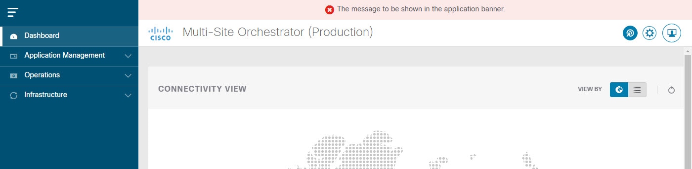
This section describes how to configure an alias for your Multi-Site Orchestrator as well as enable a custom GUI-wide banner to be displayed at the top of your screen, as shown in the following figure.

Figure 1. System Banner Display

Procedure


Step 1

Log in to your Orchestrator.

Step 2

From the left navigation pane, select Admin > System Configuration.

Step 3

Click the Edit icon to the right of the System Alias & Banners area.

This opens the System Alias & Banners settings window.

Step 4

In the Alias field, specify the system alias.

Step 5

Choose whether you want to enable the GUI banner.

Step 6

If you enable the banner, you must provide the message that will be displayed on it.

Step 7

If you enable the banner, you must choose the severity, or color, for the banner.

Step 8

Click Save to save the changes.


Login Attempts and Lockout Time

When the Orchestrator detects a significant number of failed consecutive login attempts, the user is locked out of the system to prevent unauthorized access. You can configure how failed log in attempts are treated, for example the number of failed attempts before lockout and the length of the lockout.

Note

This feature is enabled by default when you first install or upgrade to Release 2.2(1) or later.


Procedure


Step 1

Log in to your Orchestrator.

Step 2

From the left navigation pane, select Admin > System Configuration.

Step 3

Click the Edit icon to the right of the Fail Attempts & Lockout Time area.

This opens the Fail Attempts & Lockout Time settings window.

Step 4

From the Fail Attempt Settings dropdown, select the number of attempts before the user is locked out.

Step 5

From the Lockout Time (Minutes) dropdown, select the length of the lockout.

This specifies the base lockout duration once it's triggered. The timer is extended up to three times exponentially with every additional consecutive login failure.

Step 6

Click Save to save the changes.


Proxy Server

In certain deployment scenarios, such as with a combination of on-premises and cloud sites and the Orchestrator running inside a corporate network, the Orchestrator may have to access the internet and the cloud sites through a proxy. You can configure and enable proxy as described in this section.

When a proxy server is enabled, the Orchestrator will maintain a "no proxy" list of IP addresses and hostnames with which it will communicate directly bypassing the proxy. This list is a combination of user-specified hosts or domains plus all on-premises APIC sites currently added to the Orchestrator. Every time the list is updated with a new address, for example if you add a new site to the Orchestrator, the proxy service is restarted. You can minimize the service restarts by providing a complete list of your on-premises sites in advance, for example by adding an entire domain to the "no proxy" list, while configuring the proxy settings.

Procedure


Step 1

Log in to your Orchestrator.

Step 2

From the left navigation pane, select Admin > System Configuration.

Step 3

Click the Edit icon to the right of the Proxy Server area.

This opens the Proxy Settings window.

Step 4

Choose Enable to enable the proxy.

Step 5

In the Proxy Server field, specify the IP address or the hostname of your proxy server.

Step 6

In the Proxy Server Port field, specify the port number used to connect to the proxy server.

Step 7

In the No Proxy List field, provide a comma-separated list of hosts and domains that should bypass the proxy.

When specifying the list, you can provide exact IP addresses or hostnames, as well as entire domains using the wildcard (*) character. Wildcards cannot be used with IP addresses.

For example, 203.0.113.1, apic1.example.com, *.example.local.

Step 8

Click Save to save the changes.

When you configure and enable proxy, the Orchestrator application will restart.