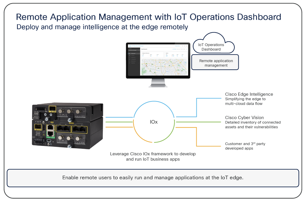
Welcome to Cisco IoT Operations Dashboard (OD)
Cisco offers an unparalleled end-to-end Internet of Things (IoT) architecture to interconnect assets, applications and data to uncover transformative business insights. Cisco IoT Operations Dashboard is a cloud-based IoT services platform that empowers operations teams to securely connect, maintain and gain insights from industrial networking devices and connected industrial assets at massive scale. With one comprehensive view of all their connected industrial assets, operation teams can uncover valuable insights that help them streamline operations and drive business continuity.
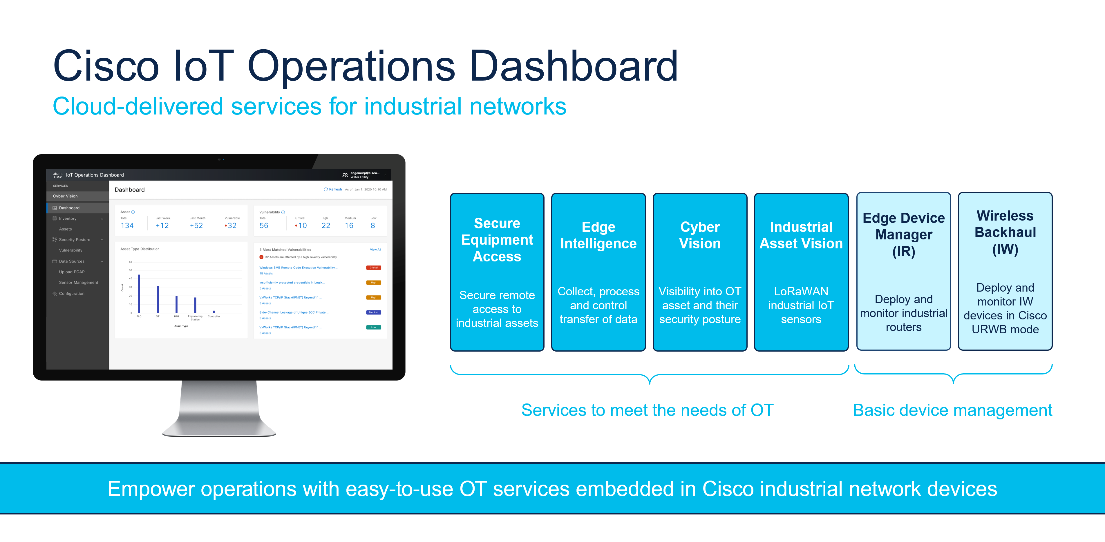
Currently, the IoT Operations Dashboard (OD) supports the following Services:
- Edge Device Manager–to configure, deploy, and monitor supported industrial network devices
- Application Manager–to manage applications for Externally-Managed devices and EDM-managed devices
- Secure Equipment Access–to connect assets deployed in remote locations
- Edge Intelligence–to enable edge to multi-cloud data orchestration
- Asset Vision–to monitor assets and facilities using Cisco industrial sensors
- Industrial Wireless–to configure and manage industrial wireless devices
- Cisco Cyber Vision–to gain full visibility into connected industrial assets and their security and vulnerability risks
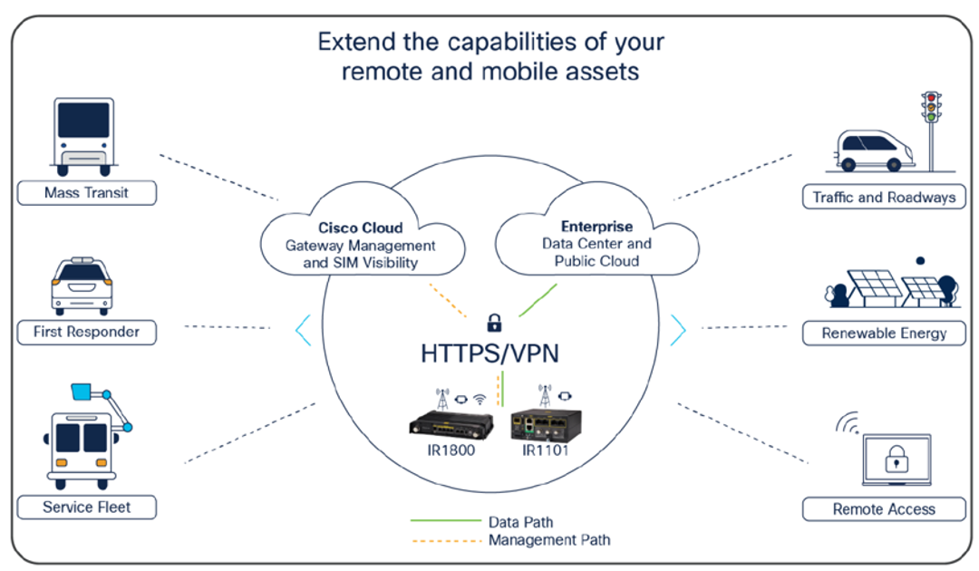
Cisco IoT Operations Dashboard is well suited to deploying IoT assets in scenarios such as:
- Industrial asset monitoring and troubleshooting--for example traffic signal controllers and signage at roadways and intersections
- Mass transit vehicles--for example buses, first responder vehicles
- Renewable energy assets, such as solar panels and wind turbines
- Connected machines, enabling vendors and providers to deliver services to ensure machines are up and running on customer sites, and scheduling preventive maintenance
- Connected assets such as ATMs, kiosks, vending machines and electric vehicle charging stations
- Extended office (field hotspot)
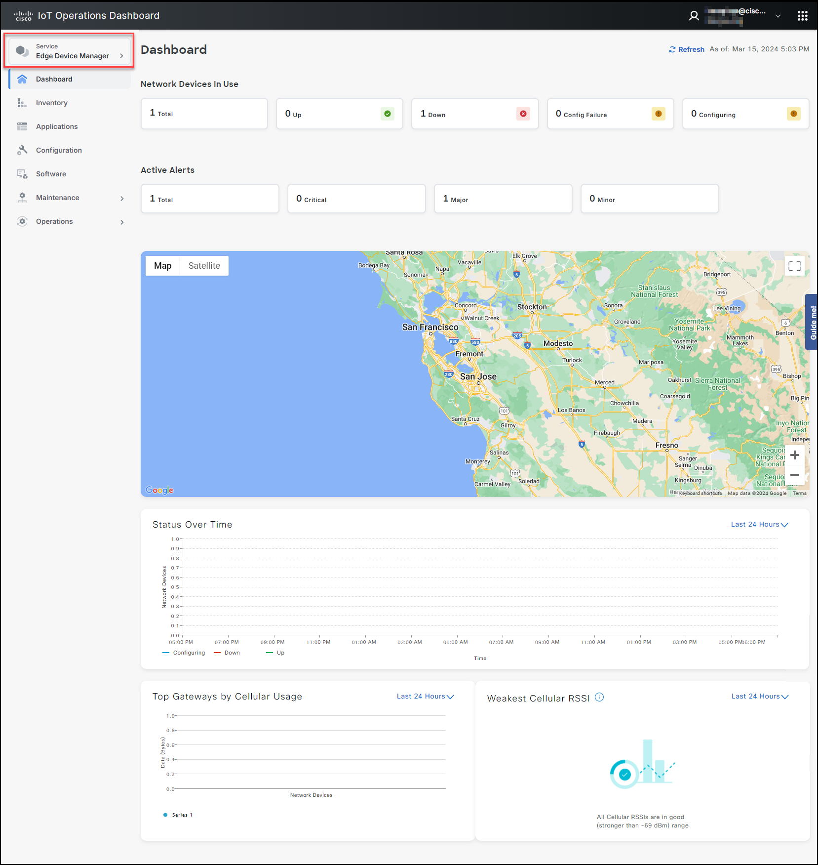
Edge Device Manager
Cisco IoT Operations Dashboard enables simplified and secure connectivity for industrial assets using Cisco industrial networking devices. Edge Device Manager service offers device management capabilities for Industrial Routers, including Cisco IR1800 series, IR1101, and IR800 series.
The industrial edge routers support many use cases with the flexibility, security, and scalability needed to unite your edge. With zero-touch deployment and resilient remote management of Cisco devices, the cloud-based Edge Device Manager on IoT Operations Dashboard enables fast setup of IoT networks.
Device Management Capabilities in IoT OD for Different Device Types
Cisco Applications Manager is a premium feature and requires an IoT OD Advantage license.
| Capability | IoT OD-Managed Devices | Externally-Managed Devices |
|---|---|---|
| Alert Rules (Notifications) | Yes | No |
| Alerts (for events generated by the device) | Yes | No |
| Configuration Management | Yes | No |
| Events Logs from Device (Via SNMP Traps) |
Yes | No |
| Firmware Upgrade | Yes | No |
| Location History | Yes | No |
| PnP Onboarding | Yes | No |
With this new offer, industrial customers can quickly increase the value of their IE3x00 switches and IR1101/1800 routers that run as the host platform for IOx applications with cloud-based service management through IoT OD. For example, with minimal effort, the existing IE3x00 devices can handle Secure Remote Access (SEA) sessions to Cisco and non-Cisco assets using SEA, implement security posture control for the network via using Cisco Cyber Vision (CCV), or capture data on edge and inject it to their cloud platforms of choice through Edge Intelligence Service on IoT OD.
Application Manager
IoT applications offer customers and ecosystem partners the ability to leverage IoT data and perform control functions within the distributed network infrastructure. Application Manager service provides life cycle management of IOx applications on network devices managed via CLI or Cisco Controllers, such as Cisco IE3x00 switches and the Cisco Industrial Routers managed by IoT Operations Dashboard Edge Device Manager (EDM). Additionally, the service allows the process of onboarding and monitoring device connectivity for externally-managed devices on the IoT OD.
The Cisco IOx application environment combines Cisco IOS and Linux. With Cisco IOx, developers benefit from familiar processes and open-source tools available with Linux and can generate applications that operate on Cisco IoT network infrastructure. For more information, see the following Cisco IOx links:
- (https://www.cisco.com/c/en/us/products/cloud-systems-management/iox/index.html)
- (https://community.cisco.com/t5/internet-of-things-iot-knowledge-base/getting-started-with-cisco-iox/ta-p/3619379)
Customers can develop IOx applications and host them on industrial network devices supported by IoT OD to leverage the value of available data from Operational Technology (OT) equipment. These applications can help customers optimize their business processes or provide value-added services to their business needs or their customers. For example, an application might provide a dashboard indicating hours of usage and downtime for connected equipment.
Application Manager allows OT and IT users utilize the IoT OD to manage the entire lifecycle of the applications with ease. For example, it enables users to install IOx apps onto supported networking devices and then update, uninstall, monitor, and troubleshoot the applications. The application life cycle management includes the capability to directly operate on the IoT OD User Interface. All management options are available for the following:
- Cisco branded IOx applications such as, Cisco SEA agent, Cyber Vision Sensor, Edge Intelligence software
- 3rd party (customer-developed) IOx applications
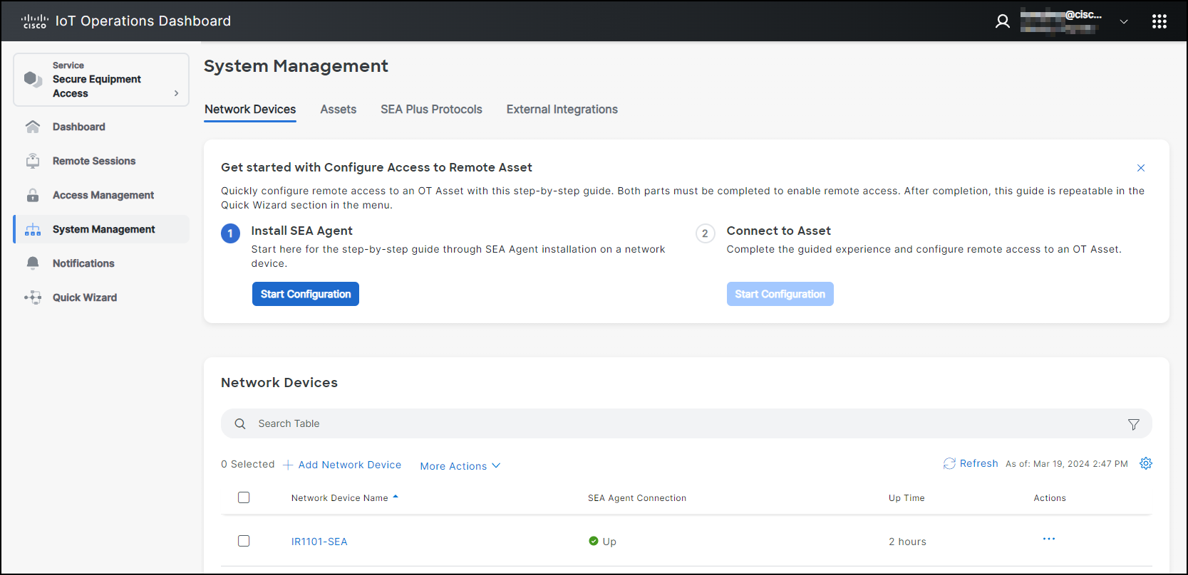
Secure Equipment Access
Cisco Secure Equipment Access (SEA) and SEA Plus are value added IoT Operations Dashboard services that enable operations teams to securely configure a remote connected asset or machine. These services provide granular access controls that can easily be managed by an operations administrator, and secure connectivity for authorized users, including internal employees and external workers. The SEA services help organizations to improve efficiency by decreasing the time and cost required for travel to remote sites for equipment maintenance or to respond to an emergency. For example, operations teams can configure equipment such as traffic signal controllers, in-vehicle dispatch systems, cameras and other systems deployed in the field and connected using Cisco Industrial Routers.
Using SEA, a worker can access a remote asset from anywhere simply by using a browser, without needing to install any additional software on their laptop. The remote equipment can be accessed using either GUI- or CLI-based methods. Supported protocols are HTTP/S, SSH, RDP for Windows-based systems, VNC, and Telnet.
SEA Plus provides further flexibility by enabling users to configure any type of equipment that supports IP connectivity. With SEA Plus, a direct, secure data connection is created between client software on the user’s computer and the remote asset, enabling the user to easily interact with and exchange files with the asset. SEA Plus supports TCP, UDP, and ICMP based protocols. IoT Operations Dashboard and SEA Plus allow the operations administrator to choose a protocol, e.g., TCP or UDP, and a port for secure communications. The feature provides users with the advanced ability to define specific channels for communications between a user and the remote system and block everything outside that.
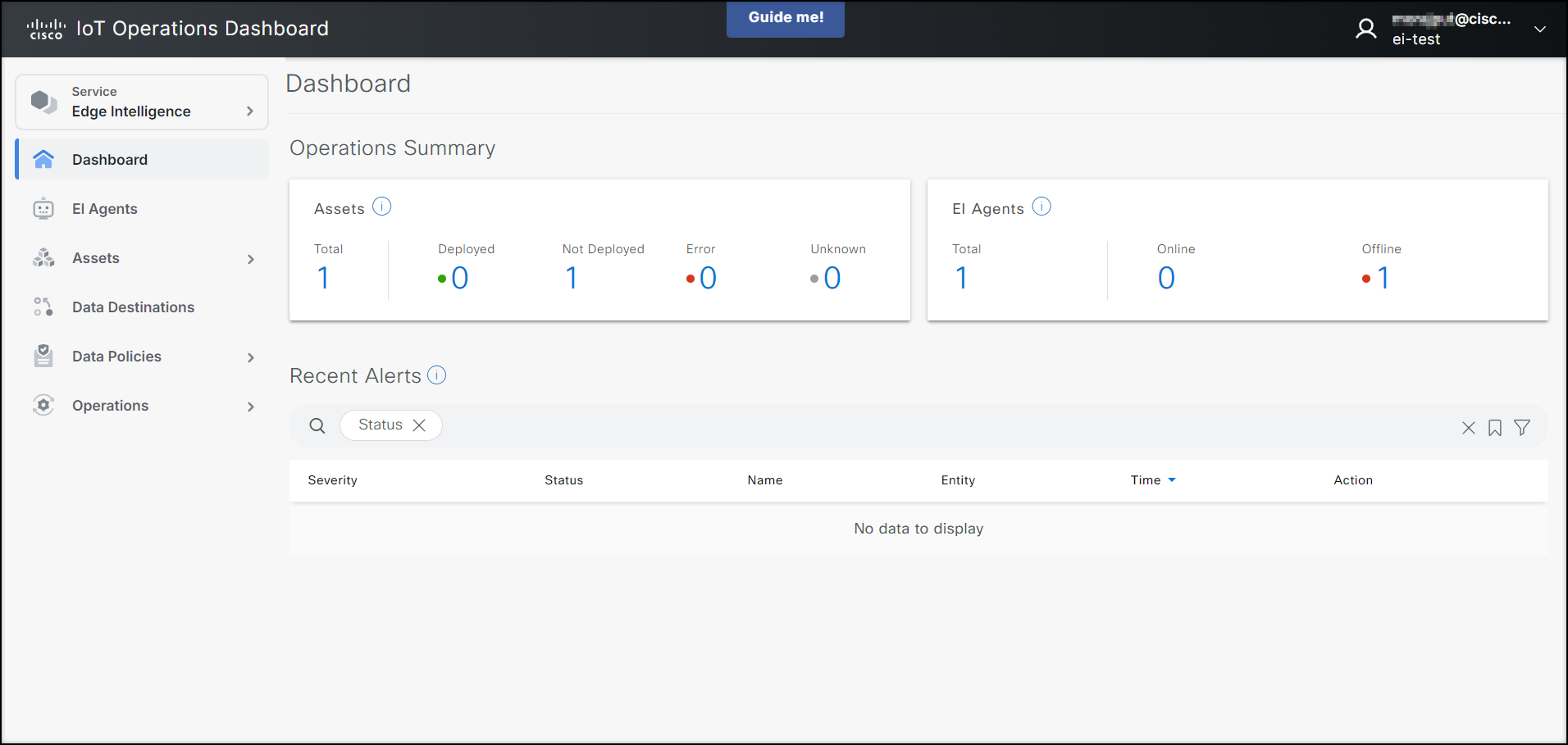
Edge Intelligence
Cisco Edge Intelligence is an edge to multi-cloud orchestrator that simplifies obtaining data from IoT assets and bringing specific data to IoT applications. Once Edge Intelligence is enabled within the IoT Operations Dashboard, operations teams and IT support staff have a single view of IoT data and network connectivity. More product and ordering information on Cisco Edge Intelligence can be found here.
Control and governance of your IoT data
Cisco Edge Intelligence has four primary functions that help you take control of your data throughout its lifecycle.
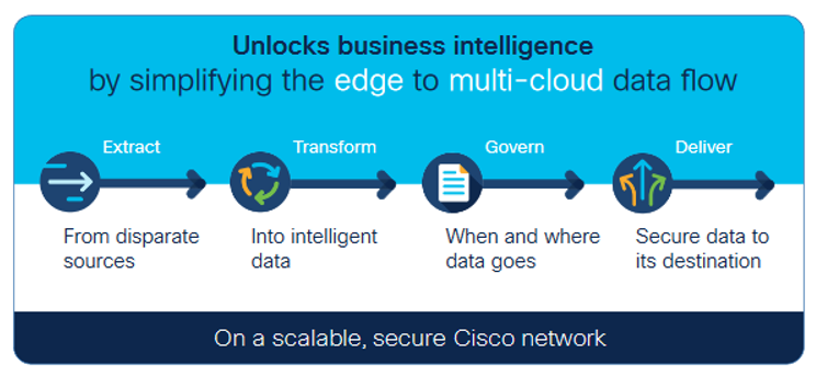
Extract: Provide simple data extraction at the edge. The software has built-in industry-standard connectors such as OPC Unified Architecture, Modbus, EtherNet Industrial Protocol (EIP)/Common Industrial Protocol (CIP), and MQ Telemetry Transport (MQTT) that allow data to be extracted from disparate sources with minimal to no coding needed. The data is then converted to industry-standard formats to enable its full use.
Transform: Once the data is extracted, Edge Intelligence enables real-time micro processing to filter, compress, or analyze data in a uniquely simple way. Via a plug-in, Edge Intelligence is fully integrated with one of the most popular tools, Microsoft Visual Studio. Developers can create, test, and deploy code without ever leaving the tool. Organizations then have the data they need from multiple aggregated sources to gain actionable insights for the best decision making.
Govern: In a heterogeneous industrial environment, many vendors compete with the customer for access and ownership of sensor data. Edge Intelligence gives back the authority to the customer to establish a central point to govern and decide where the raw or transformed data should go.
Deliver: Create data access policies at the edge and automatically deploy them with the push of a button – no more manual, error-prone, and expensive configurations. You can choose which data is sent to which destination, and even send it to multiple cloud destinations. Microsoft Azure, Software AG, and Quantela cloud users will have immediate benefits because we have done the integration work for you. Connect to them easily using a drop-down menu.
Benefits
With Cisco Edge Intelligence, you gain:
- Simplicity: Ingest IoT telemetry data and send to multiple destinations with few simple clicks.
- Scalability: Deploy IoT data logic and policies at scale across hundreds of edge devices and multiple geographic environments through a centralized management plane.
- Reliability: An all-in-one solution and integration with Cisco networking simplifies deployment versus having to use multiple vendors within a custom-built solution.
- Flexibility & Future Proofing: A plugin for Microsoft Visual Code allows you to extend intelligence in a secured sandbox environment. Security: State of the art technology throughout the stack secures your solution at all levels, from secure bootstrapping to agent installation and policy deployment.
For more information, visit www.cisco.com/go/edgeintelligence.
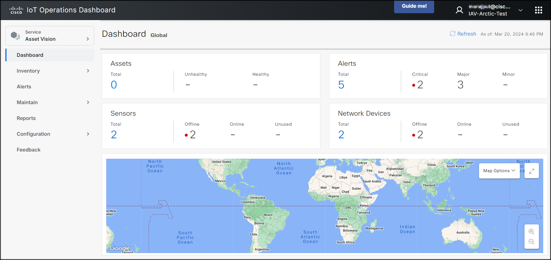
Industrial Asset Vision
Cisco Industrial Asset Vision (IAV) is a full solution to monitor assets and facilities using Cisco ruggedized sensors. It uses LoRaWAN wireless Cisco industrial sensors to provide simple and powerful visibility into your business-critical environments to keep your assets up and running efficiently—even in the harshest environments. Once Industrial Asset Vision is enabled within the IoT Operations Dashboard, operations teams and IT support staff can have a single view across Cisco industrial sensors and network connectivity. More product and licensing information on Cisco Industrial Asset Vision can be found here.
The Cisco Industrial Asset Vision product enables the following use cases:
- Outdoor asset tracking
- Facility environment (temperature and humidity)
- Cold chain (temperature and humidity)
- Facility ingress and egress (door/window)
- Water leak detection
- Motion and light detection
See the IAV Introduction Video to learn more, and the IAV Demo Video to see Asset Vision in action.
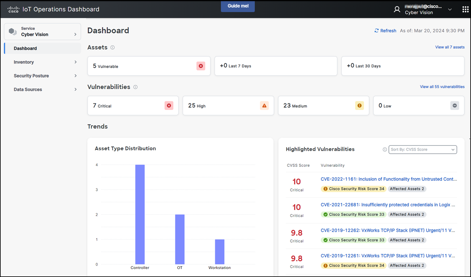
Cisco Cyber Vision
Cisco Cyber Vision provides organizations full visibility into assets connected to their industrial networks, so they can better manage their inventory and understand how to limit their exposure to cyber threats. Cyber Vision automatically builds a detailed inventory of all connected assets, including their vulnerabilities, rack slot configurations, vendor references, serial numbers, firmware and software versions, and more. You now have the insights you need to drive cybersecurity hygiene and reduce your exposure to cyber risks.
Cyber Vision embeds visibility capabilities into Cisco industrial routers installed in your operational environment. There is no need for additional security appliances. Information sent to Cisco IoT Operations Dashboard is light-weight metadata which saves on WAN costs and enables deployment at scale.
Industrial Wireless
Cisco Industrial Wireless service is a cloud-based dashboard that securely provisions and manages industrial wireless devices. These access points run on URWB software. IoT Operations Dashboard allows you to monitor the range of access points specifically designed for offering extended, high-performance wireless connectivity in outdoor and harsh industrial environments. These industrial wireless devices are moving assets in mission-critical applications, such as Automated Guided Vehicles (AGVs), Autonomous Mobile Robots (AMRs), and tele-remote devices requiring reliable wireless connectivity. This option extends your network where running fiber isn’t feasible or is too costly. The product information on Cisco Industrial Wireless service can be found here.
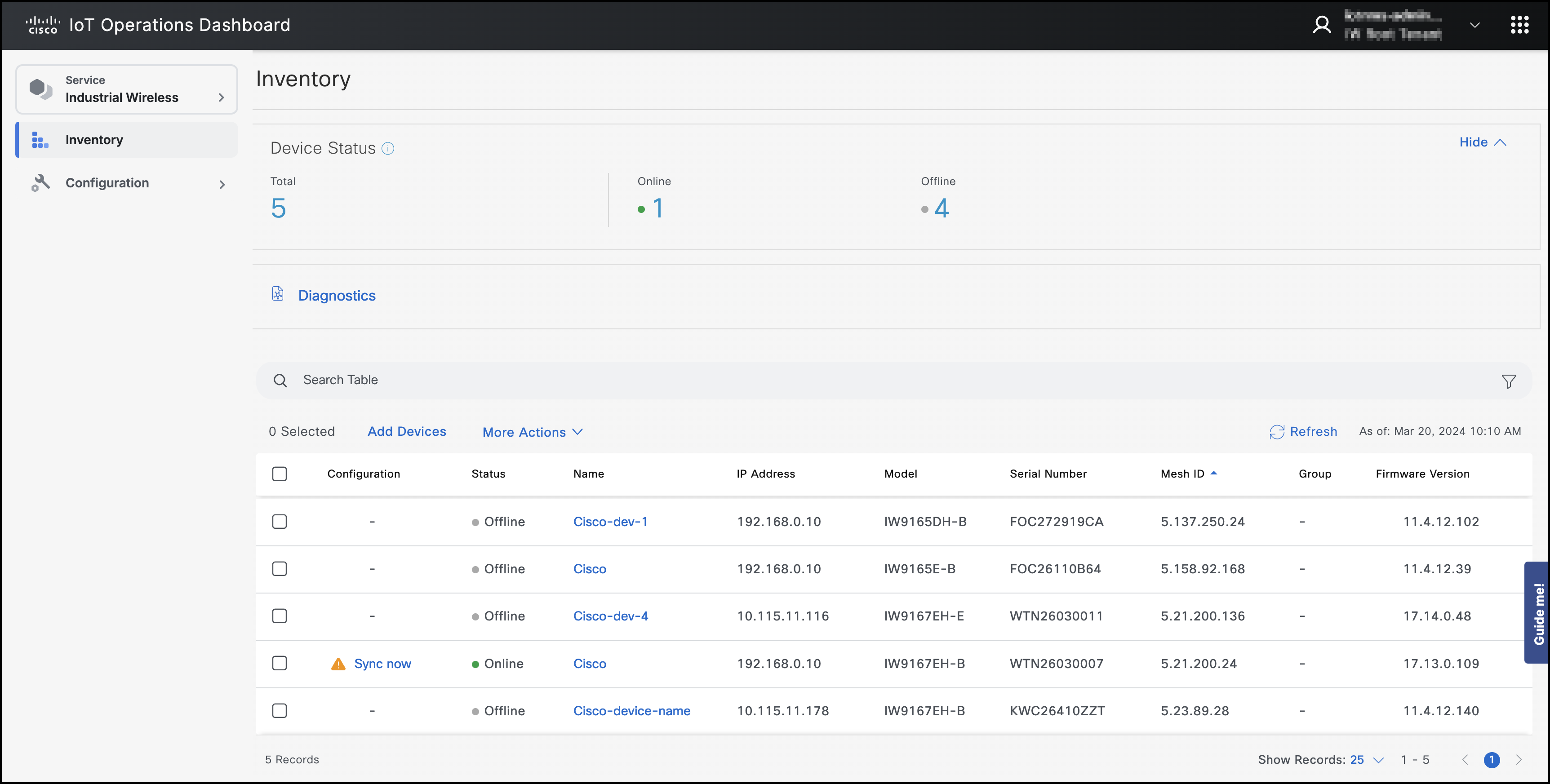
The IoT OD displays the unified health information of all the industrial wireless devices that are part of the organization and allows for the deployment and configuration of industrial wireless devices. The Dashboard shows details such as name, device status, IP address, model, serial number information, mesh ID, and firmware version of the industrial wireless device.
For more information, visit Industrial Wireless product information.
Using the IoT Operations Dashboard
The new screen of IoT Operation Dashboard (IoT OD) allows you to manage all your IoT OD services from a single centralized platform. This feature lets you switch between services on the dashboard at your convenience.
The IoT OD contains a left navigation pane and a right work pane. The left navigation pane displays all the services that is available for your organization.
Click on the service you wish to access to view its menu options and the dashboard. The service menu options along with the dashboard will be displayed only if the service selected is enabled and procured for your organization.
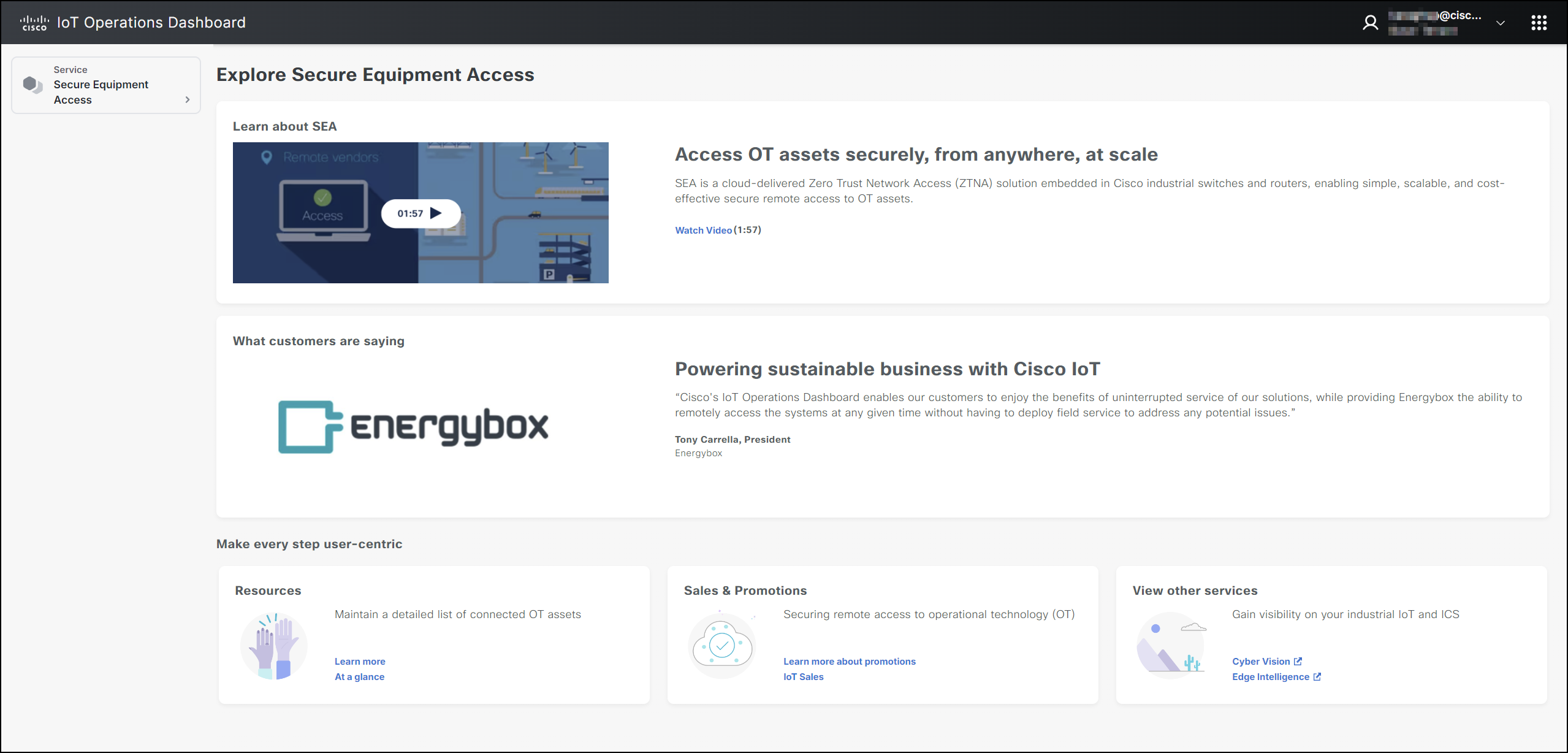
In the example below, you can view the SEA service selected on the left pane, with menu options appearing under the SEA tab and the SEA dashboard displayed on the right pane.
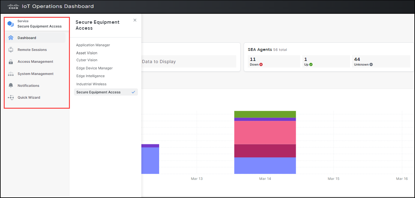
To view all other services available within IoT OD, click on the current service tab on the left navigation pane. This action will open another side-panel referred to as the service switcher menu, displaying a list of services.
Note: The Edge Device Manager (EDM) and Industrial Asset Vision (IAV) services are visible in the service switcher menu only if your organization has procured and enabled them; otherwise, they won't be displayed.
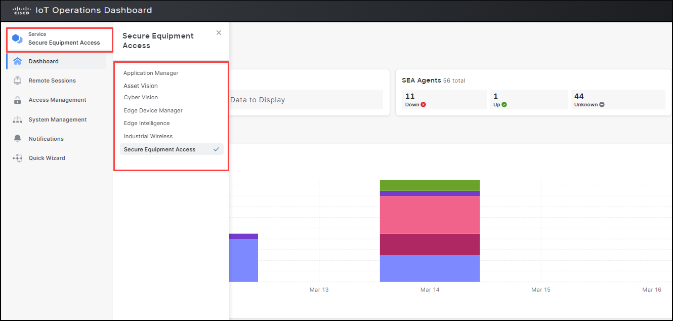
To know more details about the services you have not procured, simply click on the service you wish. The information pertaining to that service is displayed on the right pane. This lets you browse through all the details offered by that service.
In the example below, we have selected the Secure Equipment Access (SEA) to display its details.