Network Security within a Converged Plantwide Ethernet Architecture
Bias-Free Language
The documentation set for this product strives to use bias-free language. For the purposes of this documentation set, bias-free is defined as language that does not imply discrimination based on age, disability, gender, racial identity, ethnic identity, sexual orientation, socioeconomic status, and intersectionality. Exceptions may be present in the documentation due to language that is hardcoded in the user interfaces of the product software, language used based on RFP documentation, or language that is used by a referenced third-party product. Learn more about how Cisco is using Inclusive Language.
- Updated:
- December 21, 2018
Chapter: Implementation of Use Cases
- Visibility and Identification of Network Devices and IACS Assets in the Cell/Area Zone
- Security Group Policy Assignment of IACS Assets in Industrial Zone
- Network Detection of Network Devices and IACS Assets
- Malware Detection of Flows in Cell/Area Zone and Level-3 Site Operations
- OT Managed Remote User (Employee or Partner) Accessing from (Enterprise or Internet) to a Network Device or an IACS Asset
- Device Onboarding
Implementation of Use Cases
This section describes the implementation of the Network Security use cases documented in this CPwE Network Security CVD DIG. The objective is to provide more details about each of the following use cases and also how different components, such as IES, ISE, NMT, and Stealthwatch work together to support these use cases. This section describes the following use cases:
- Visibility and Identification of Network Devices and IACS Assets in the Cell/Area Zone
- Security Group Policy Assignment of IACS Assets in Industrial Zone
- Network Detection of Network Devices and IACS Assets
- Malware Detection of Flows in Cell/Area Zone and Level-3 Site Operations
- OT Managed Remote User (Employee or Partner) Accessing from (Enterprise or Internet) to a Network Device or an IACS Asset
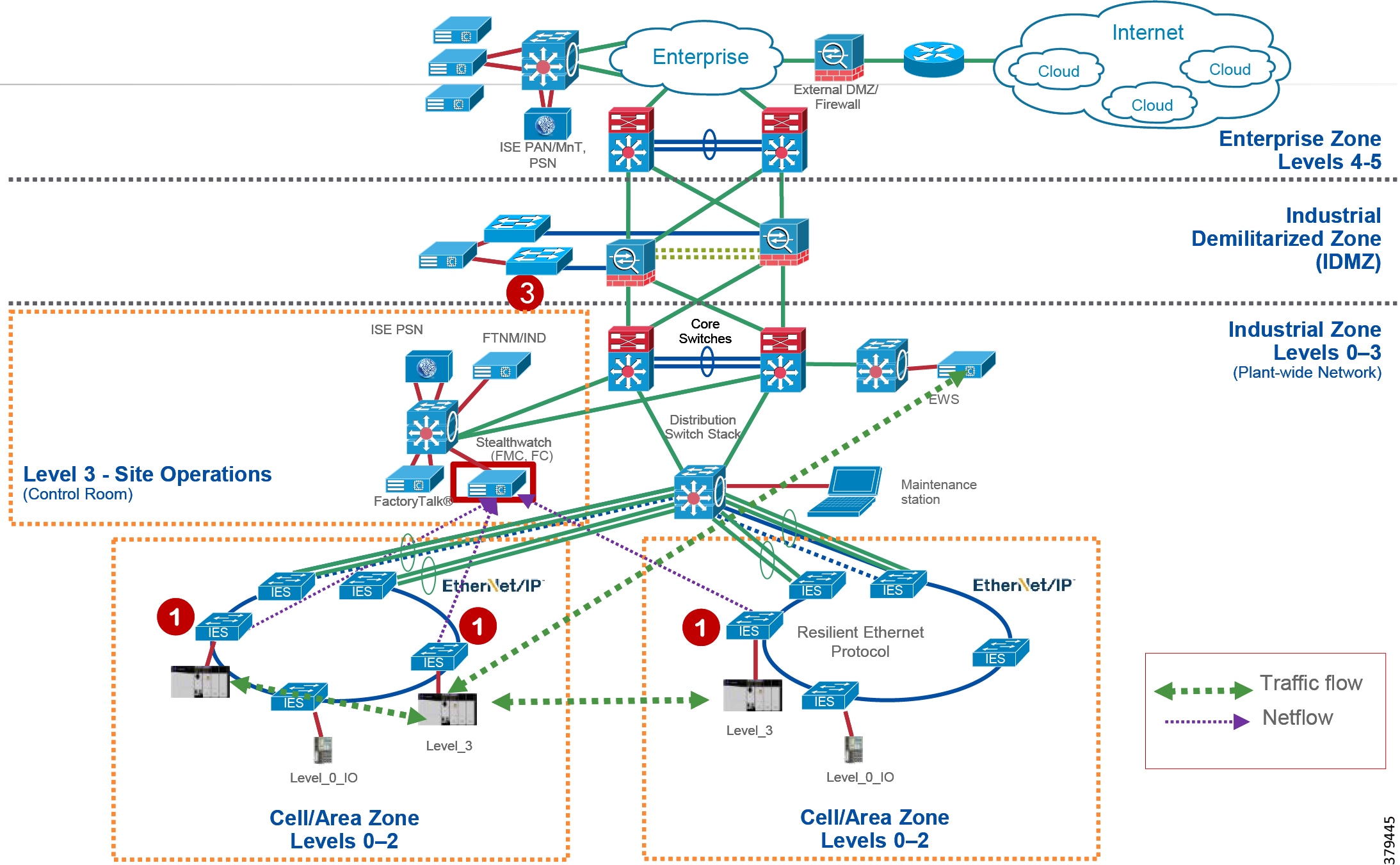
Visibility and Identification of Network Devices and IACS Assets in the Cell/Area Zone
The purpose of this use case is to show how an OT control system engineer and IT security architect can work together to gain visibility of the network devices and IACS assets in the Cell/Area Zone. As explained in Segmentation—High Level in “CPwE Network Security Design Considerations,” to segment traffic flows going across in East-West or North-South direction it is important that the IT security architect gain visibility of the current network topology in the plant-wide network. The visibility must be granular enough that the IT security architect can know the type of the IACS asset—Controller, I/O, drive, HMI, and others. Figure 5-1 illustrates the high-level steps to perform this use case.
Figure 5-1 Visibility and Identification of Network Devices and IACS Assets in the Cell/Area Zone
1.![]() An OT control system engineer defines the IACS Asset Discovery profiles for IACS assets and the networking devices in NMT. Refer to Creating Asset Discovery Profile in Chapter4, “Configuring the Infrastructure”
An OT control system engineer defines the IACS Asset Discovery profiles for IACS assets and the networking devices in NMT. Refer to Creating Asset Discovery Profile in Chapter4, “Configuring the Infrastructure”
2.![]() OT control system engineer scans the IACS assets and the networking devices and verifies that the IACS assets and networking devices are grouped in Asset Inventory section of NMT. Refer to Asset Inventory in Chapter4, “Configuring the Infrastructure”
OT control system engineer scans the IACS assets and the networking devices and verifies that the IACS assets and networking devices are grouped in Asset Inventory section of NMT. Refer to Asset Inventory in Chapter4, “Configuring the Infrastructure”
3.![]() The IT security architect configures the pxGrid between NMT and ISE. Refer to Configuring pxGrid between Cisco ISE and NMT in Chapter4, “Configuring the Infrastructure”
The IT security architect configures the pxGrid between NMT and ISE. Refer to Configuring pxGrid between Cisco ISE and NMT in Chapter4, “Configuring the Infrastructure”
4.![]() IT security architect configures profiling policies in ISE to profile the IACS assets based on the attributes provided by NMT. Refer to Profiling in Cisco ISE in Chapter4, “Configuring the Infrastructure”
IT security architect configures profiling policies in ISE to profile the IACS assets based on the attributes provided by NMT. Refer to Profiling in Cisco ISE in Chapter4, “Configuring the Infrastructure”
5.![]() ISE is able to identify Level_1_Controller in a Cell/Area Zone. Refer to Level_1_controller Policy in Chapter4, “Configuring the Infrastructure”
ISE is able to identify Level_1_Controller in a Cell/Area Zone. Refer to Level_1_controller Policy in Chapter4, “Configuring the Infrastructure”
6.![]() ISE is able to identify Level_0_IO in a Cell/Area Zone. Refer to Level_0_IO_policy in Chapter4, “Configuring the Infrastructure”
ISE is able to identify Level_0_IO in a Cell/Area Zone. Refer to Level_0_IO_policy in Chapter4, “Configuring the Infrastructure”
7.![]() ISE is able to identify Level_3 in a Cell/Area Zone. Refer to Level_3_policy in Chapter4, “Configuring the Infrastructure”
ISE is able to identify Level_3 in a Cell/Area Zone. Refer to Level_3_policy in Chapter4, “Configuring the Infrastructure”
Security Group Policy Assignment of IACS Assets in Industrial Zone
This use case describes in detail about how to achieve segmentation of different traffic flows in a Cell/Area Zone. To understand traffic flows, refer to Traffic Flows in a Network in Chapter3, “CPwE Network Security Design Considerations” The idea behind segmentation is defined in Segmentation—High Level in Chapter3, “CPwE Network Security Design Considerations” Figure 5-2 provides the steps that an IT security architect needs to perform to achieve segmentation of different traffic flows.
Figure 5-2 Segmentation of Traffic Flows in Cell/Area Zone
1.![]() The IT security architect must configure port-based authentication on all the IES. Refer to Configuring Port-based Authentication in Chapter4, “Configuring the Infrastructure”
The IT security architect must configure port-based authentication on all the IES. Refer to Configuring Port-based Authentication in Chapter4, “Configuring the Infrastructure”
2.![]() The IT security architect must configure TrustSec SGTs for different IACS assets - Level_1_Controller, Level_0_IO, and Level_3 in ISE. Refer to Configuring SGT Components in Chapter4, “Configuring the Infrastructure”
The IT security architect must configure TrustSec SGTs for different IACS assets - Level_1_Controller, Level_0_IO, and Level_3 in ISE. Refer to Configuring SGT Components in Chapter4, “Configuring the Infrastructure”
3.![]() The IT security architect must configure Authentication and Authorization policy in ISE. Refer to Authentication Policy and Authorization Policies in Chapter4, “Configuring the Infrastructure”
The IT security architect must configure Authentication and Authorization policy in ISE. Refer to Authentication Policy and Authorization Policies in Chapter4, “Configuring the Infrastructure”
4.![]() The IT security architect must configure SXP tunnels from IES and the distribution switch to ISE. Refer to Configuring SXP Tunnel on an IES in Chapter4, “Configuring the Infrastructure”
The IT security architect must configure SXP tunnels from IES and the distribution switch to ISE. Refer to Configuring SXP Tunnel on an IES in Chapter4, “Configuring the Infrastructure”
5.![]() The IT security architect must configure the TrustSec Policy Matrix on ISE. Refer to Configuring TrustSec Access Policy Matrix in Chapter4, “Configuring the Infrastructure”
The IT security architect must configure the TrustSec Policy Matrix on ISE. Refer to Configuring TrustSec Access Policy Matrix in Chapter4, “Configuring the Infrastructure”
6.![]() The IT security architect must configure the enforcement on the Cisco Catalyst 3850 distribution switch. Refer to Configuring Distribution Switch—Cisco Catalyst 3850 in Chapter4, “Configuring the Infrastructure”
The IT security architect must configure the enforcement on the Cisco Catalyst 3850 distribution switch. Refer to Configuring Distribution Switch—Cisco Catalyst 3850 in Chapter4, “Configuring the Infrastructure”
Network Detection of Network Devices and IACS Assets
This use case describes how an IT security architect can use Stealthwatch along with NetFlow enabled on IES and Cisco Catalyst 3850 to monitor the network flows in the plant-wide network. To detect traffic flows occurring in a plant-wide network, it is important that NetFlow is enabled on all the networking devices to capture the traffic flows that are sent to FlowCollector. Stealthwatch Management Console (SMC) retrieves the flow data from the FlowCollector and runs pre-built algorithms to display the network flows and also detect and warn if there is any malicious or abnormal behavior occurring in the network. In this CPwE Network Security CVD, three flows are shown to demonstrate the capability of Stealthwatch using NetFlow:
- Traffic between IACS assets in a Cell/Area Zone (Intra-Cell/Area Zone).
- Traffic between Level_3 IACS assets across the Cell/Area Zone (East-West or Inter-Cell/Area Zonel traffic).
- Traffic between the EWS server and a Level_3 IACS asset (North-South) traffic.
Figure 5-3 Network Flow Detection in Plant-wide Network
The following steps must be performed by the IT security architect to detect the above-mentioned flows:
1.![]() IT security architect must enable NetFlow on all the IES and the Cisco Catalyst 3850 switches. Refer to Configuring NetFlow on IES in Chapter4, “Configuring the Infrastructure”
IT security architect must enable NetFlow on all the IES and the Cisco Catalyst 3850 switches. Refer to Configuring NetFlow on IES in Chapter4, “Configuring the Infrastructure”
2.![]() IT security architect must use the host group feature in Stealthwatch to focus on certain flows if needed. A host group is essentially a virtual container of multiple host IP addresses or IP address ranges that have similar attributes, such as location, function, or topology. By grouping hosts into host groups, you can control how the Stealthwatch Flow Collectors monitor and respond to the behavior of those hosts as a group, rather than individually.
IT security architect must use the host group feature in Stealthwatch to focus on certain flows if needed. A host group is essentially a virtual container of multiple host IP addresses or IP address ranges that have similar attributes, such as location, function, or topology. By grouping hosts into host groups, you can control how the Stealthwatch Flow Collectors monitor and respond to the behavior of those hosts as a group, rather than individually.
To monitor specific application traffic such as CIP, the IT security architect must configure host groups based on subnets associated with the IACS assets and then create an appropriate filter to monitor CIP traffic. Example attributes for EtherNet/IP traffic would be TCP 44818 for CIP class 3 explicit traffic and UDP 2222 for CIP class 1 implicit I/O traffic.
To configure host groups refer to https://www.cisco.com/c/dam/en/us/td/docs/security/stealthwatch/management_console/smc_users_guide/SW_6_9_0_SMC_Users_Guide_DV_1_2.pdf

Note![]() Although Cisco Catalyst 6800 and 4500X core switches support NetFlow, the CPwE Network Security CVD was only tested and validated with NetFlow enabled on the IES and Catalyst 3850. Cisco and Rockwell Automation recommend that NetFlow be enabled throughout the plant-wide architecture.
Although Cisco Catalyst 6800 and 4500X core switches support NetFlow, the CPwE Network Security CVD was only tested and validated with NetFlow enabled on the IES and Catalyst 3850. Cisco and Rockwell Automation recommend that NetFlow be enabled throughout the plant-wide architecture.
Malware Detection of Flows in Cell/Area Zone and Level-3 Site Operations
This section discusses how Stealthwatch using NetFlow data collected by the FlowCollector detects malware flows occurring in a plant-wide network. When malware is spreading in the network, it becomes very difficult to pinpoint where the malware propagation is occurring. An IT security architect needs to identify the source of the problem and then develop a remediation plan to address the problem. Stealthwatch has many inbuilt machine learning algorithms that can assist an IT security professional in detecting possible malware propagation in the network. Stealthwatch can detect any abnormal behavior occurring in the network and can also provide the IP address of the device that is causing the propagation. This information greatly simplifies the detection process.
Without Stealthwatch implemented in the network, the normal operation done by the IT security architect is to perform a number of steps that may involve many time-consuming operations, such as shutting down parts of the network, going through logs of many devices, checking the DNS log, and enabling debugs on many other devices to isolate the problem. All these steps not only take time to isolate, but also increase the risk of other vulnerable devices becoming infected. When active malware is detected, then quickly formulating a remediation plan is essential in building a defense against malware.
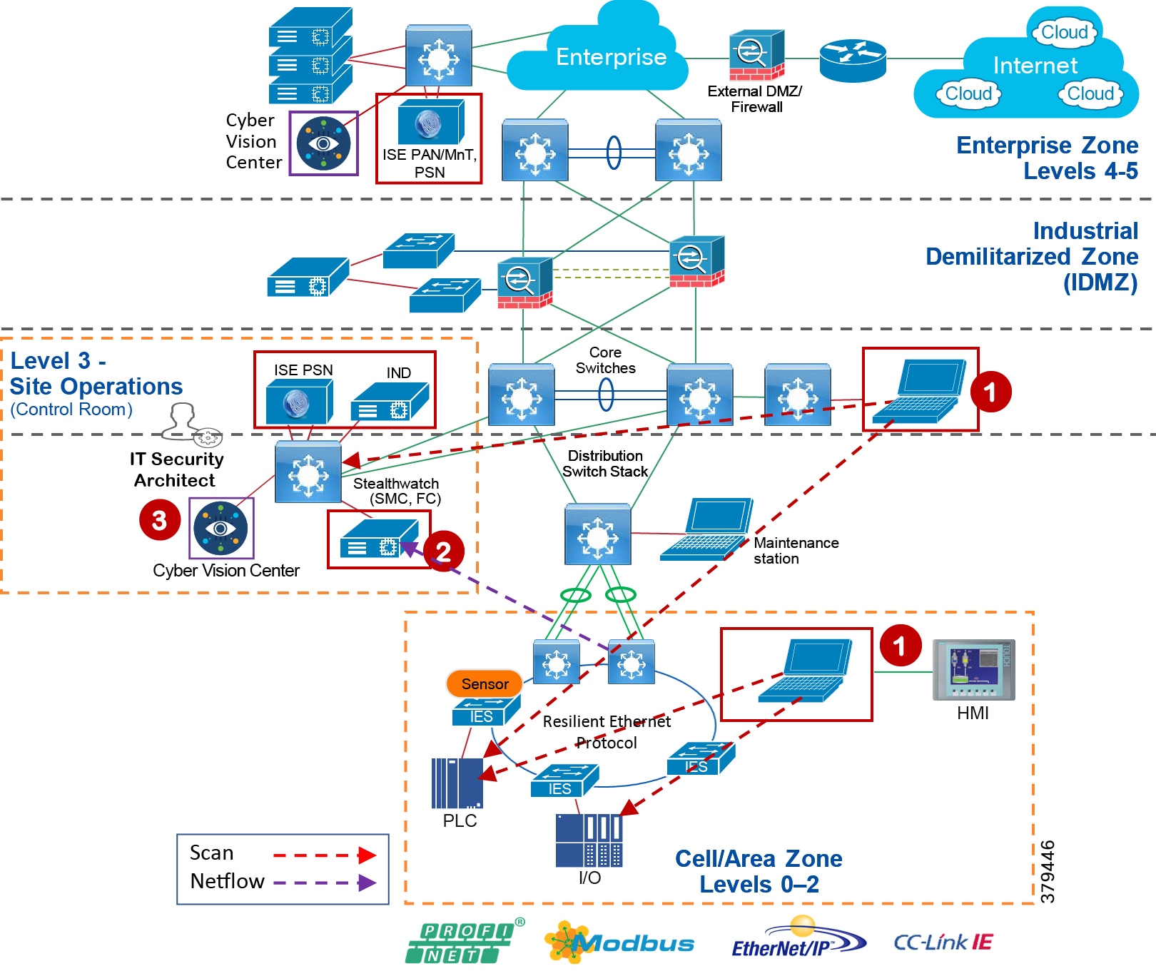
The malware behavior is to immediately scan the network to identify any other vulnerable devices in the plant-wide network. In this CPwE Network Security CVD, two traffic flows related to malware are discussed:
- An infected laptop attached to an IES. Figure 5-4 shows an example of how a scan can be performed by an infected laptop.
Figure 5-4 Scan by an Infected Laptop
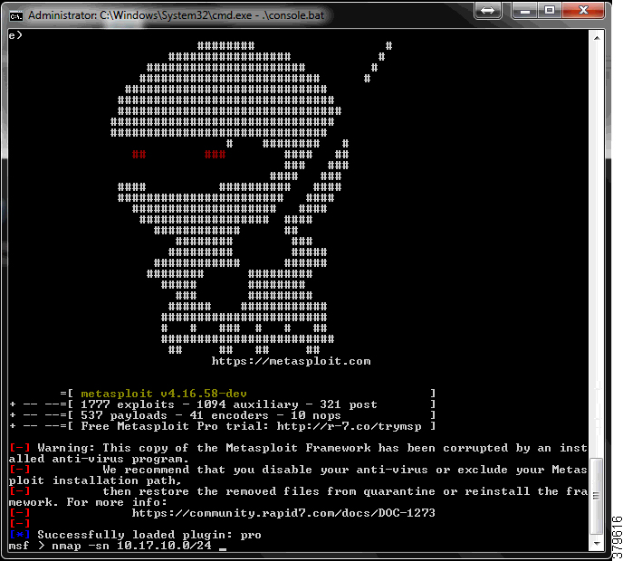
In both the cases, the infected laptop attempts to scan the entire IP address range to identify the next possible targets and attempt to infect them. Stealthwatch would immediately detect a possible infiltration by generating an alarm under High Concern Index. Any alarm that comes under High Concern Index must be immediately taken into consideration. Figure 5-5 shows how an alarm is displayed in the Stealthwatch Management Console. In Figure 5-5, the host 10.20.25.221 is attempting to do a scan for the 10.17.10.0/24 network.
Figure 5-5 Alarm Displayed in Stealthwatch Management Console
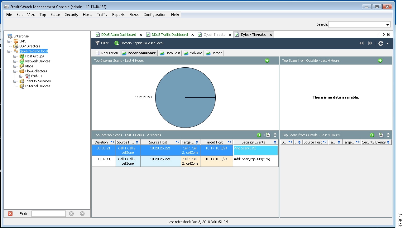
To understand more about alarms refer to:
https://www.cisco.com/c/dam/en/us/td/docs/security/stealthwatch/management_console/smc_users_guide/SW_6_9_0_SMC_Users_Guide_DV_1_2.pdf
Figure 5-6 shows the scenario where an infected laptop is connected to Cell/Area Zone or Level_3 operations and is being detected by the Stealthwatch. The steps involved are the following:
1.![]() The IES in the Cell/Area Zone or the distribution switch in Level_3 operations is enabled with NetFlow. Refer to Configuring NetFlow on IES in Chapter4, “Configuring the Infrastructure”
The IES in the Cell/Area Zone or the distribution switch in Level_3 operations is enabled with NetFlow. Refer to Configuring NetFlow on IES in Chapter4, “Configuring the Infrastructure”
2.![]() The Stealthwatch Management Console reports an alarm indicating that there is a malicious activity occurring in the network.
The Stealthwatch Management Console reports an alarm indicating that there is a malicious activity occurring in the network.
3.![]() IT security architect responds to the alarm by planning the next stage of remediation that can involve doing further investigation, restricting the access of the IACS asset, and so on.
IT security architect responds to the alarm by planning the next stage of remediation that can involve doing further investigation, restricting the access of the IACS asset, and so on.
Figure 5-6 Detection of Malware in the Cell/Area Zone
OT Managed Remote User (Employee or Partner) Accessing from (Enterprise or Internet) to a Network Device or an IACS Asset
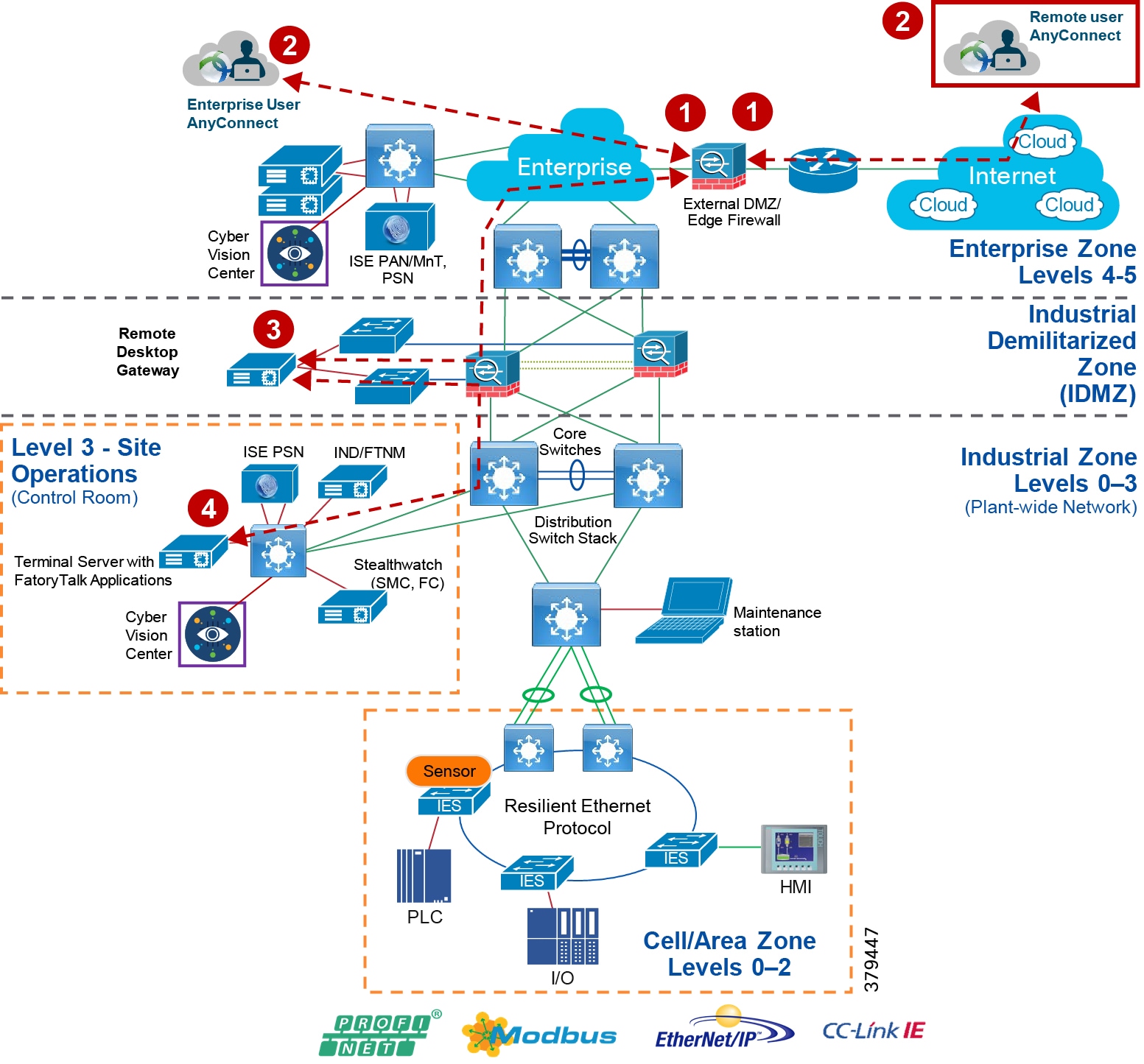
This use case describes how a remote user employee or partner can access a networking device or an IACS asset from either internet or Enterprise Zone. The Securely Traversing IACS Data Across the Industrial Demilitarized Zone Design and Implementation Guide (for best practices, see Appendix A, “References” for links to the CPwE IDMZ CVD DIG) that Cisco and Rockwell Automation team has developed provides design considerations and implementation details for providing remote access. The high-level steps for the remote access solution in CPwE IDMZ CVD as described in Figure 5-7 are the following:
1.![]() A remote VPN gateway (ASA firewall) is enabled with VPN group that authenticates a remote user and authorizes a service, which in this case is to access a remote desktop gateway in the IDMZ.
A remote VPN gateway (ASA firewall) is enabled with VPN group that authenticates a remote user and authorizes a service, which in this case is to access a remote desktop gateway in the IDMZ.
2.![]() The remote user, either employee or partner, uses a remote access VPN client (Cisco AnyConnect) to connect to the remote VPN gateway (ASA Firewall) and establishes a VPN session.
The remote user, either employee or partner, uses a remote access VPN client (Cisco AnyConnect) to connect to the remote VPN gateway (ASA Firewall) and establishes a VPN session.
3.![]() From the remote VPN gateway a connection is established to the remote desktop gateway in the IDMZ.
From the remote VPN gateway a connection is established to the remote desktop gateway in the IDMZ.
4.![]() From the remote desktop gateway, a connection is established to the Terminal Server with FactoryTalk applications in the Level_3 - Site Operations.
From the remote desktop gateway, a connection is established to the Terminal Server with FactoryTalk applications in the Level_3 - Site Operations.
Figure 5-7 Remote User Access in CPwE Network
This use case builds on the previous Securely Traversing IACS Data Across the Industrial Demilitarized Zone CVD and expands the remote user use case by providing the means for an OT control system engineer to influence the remote access. In the CPwE IDMZ CVD, when a remote user needs access an OT control system engineer opens a request to IT security architect to enable remote access for IACS assets. The remote user than accesses the desired IACS asset. However, when the remote user no longer needs access to the IACS asset, then the OT control system engineer must open another case for removing access for a partner or an employee who no longer needs access. This process works, but when access is not removed in time then there could be a situation where a remote user has access to a networking device or IACS asset for longer than desired. Also, having this access open for a longer duration can open a window where a hacker can exploit this access to gain access to the networking device or IACS asset.
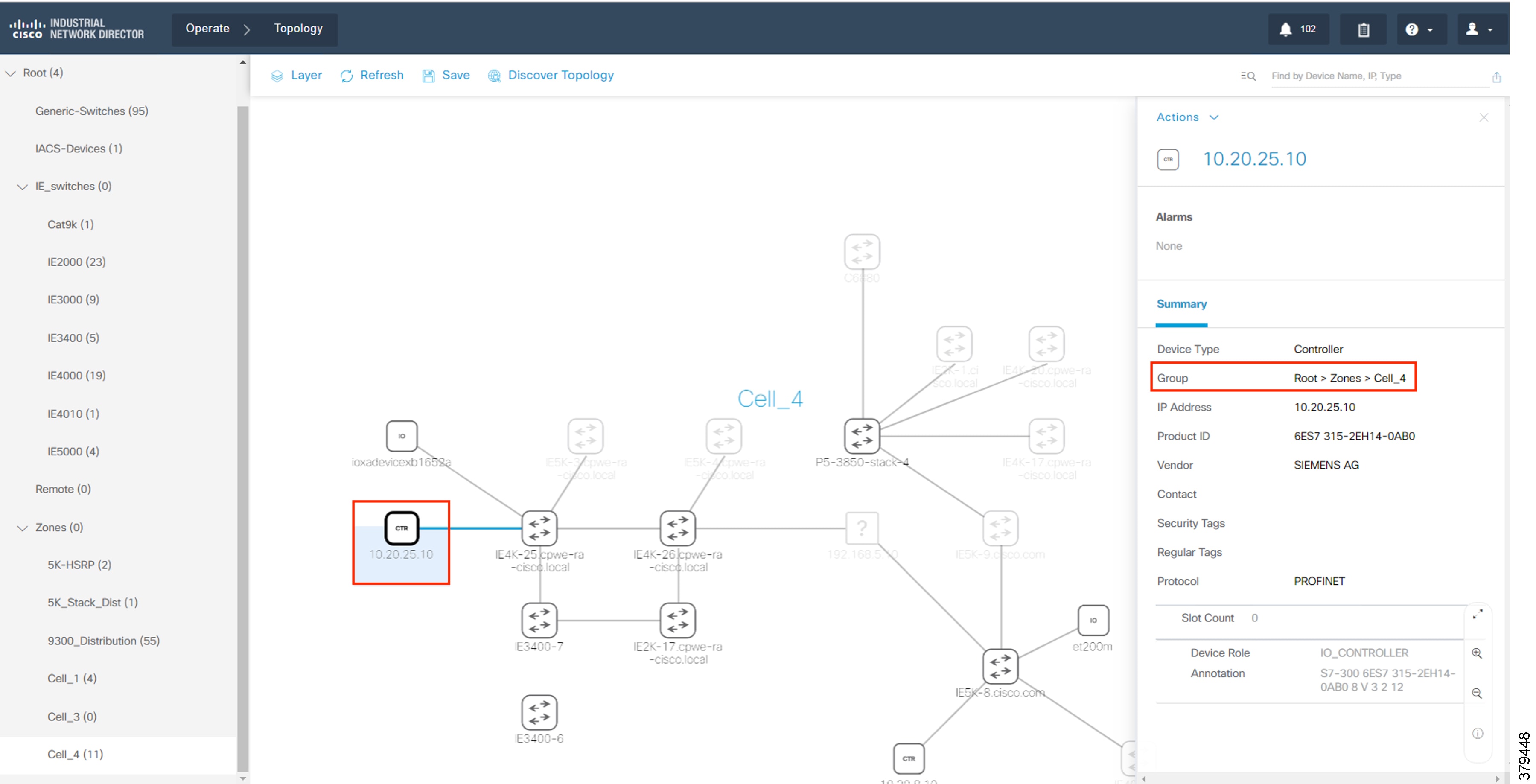
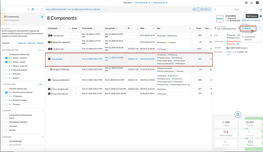
ISE-NMT integration via pxGrid provides a way for an OT control system engineer to express operational intent to ISE using NMT tool. The OT control system engineer expresses the intent by modifying the group of the networking device or IACS asset to a different group. In this CPwE Network Security CVD, a separate group called Remote_Access was defined to enable this feature. When an OT control system engineer changes the group of the IACS asset to the Remote_Access group, then remote access is enabled for that IACS asset and when the IACS asset is moved back to the original group, then the remote access to the IACS asset is revoked. The operation that needs to be done is to modify the group information of the IACS asset. Figure 5-8 shows the group information of an asset.
Figure 5-8 Modifying the Group Information of an IACS Asset
In this CPwE Network Security CVD, the remote access use case is demonstrated by creating a separate group called Remote. A device that needs Remote_Access needs to be moved to this group called Remote. When such an action is performed the following events are triggered:
1.![]() The NMT sends a new device attribute “Remote” to ISE, which ISE reads as “assetGroup”. Refer to Remote_Access in Chapter4, “Configuring the Infrastructure”
The NMT sends a new device attribute “Remote” to ISE, which ISE reads as “assetGroup”. Refer to Remote_Access in Chapter4, “Configuring the Infrastructure”
2.![]() ISE classifies this device as Remote_Access and since there is a new classification, ISE issues Change of Authorization to the IACS asset. This triggers a new authentication/authorization, which results in a new SGT assignment “Remote_Access”. Refer to Remote_Access in Chapter4, “Configuring the Infrastructure”
ISE classifies this device as Remote_Access and since there is a new classification, ISE issues Change of Authorization to the IACS asset. This triggers a new authentication/authorization, which results in a new SGT assignment “Remote_Access”. Refer to Remote_Access in Chapter4, “Configuring the Infrastructure”
3.![]() The Cisco Catalyst 3850 distribution switch downloads the new Secure Group Access Control (SGACL) from the ISE to allow access to Remote_Access. Refer to Configuring TrustSec Access Policy Matrix and Enforcement in Chapter4, “Configuring the Infrastructure” The traffic would flow from the FactoryTalk Application Server to the IACS asset.
The Cisco Catalyst 3850 distribution switch downloads the new Secure Group Access Control (SGACL) from the ISE to allow access to Remote_Access. Refer to Configuring TrustSec Access Policy Matrix and Enforcement in Chapter4, “Configuring the Infrastructure” The traffic would flow from the FactoryTalk Application Server to the IACS asset.
4.![]() Once the access to the IACS asset has been completed, the OT control system engineer moves the IACS asset back to the original group.
Once the access to the IACS asset has been completed, the OT control system engineer moves the IACS asset back to the original group.
5.![]() The NMT communicates the new group information to ISE, which derives this information using assetTag. ISE would profile this as normal IACS asset. Refer to Level_1_controller Policy in Chapter4, “Configuring the Infrastructure”
The NMT communicates the new group information to ISE, which derives this information using assetTag. ISE would profile this as normal IACS asset. Refer to Level_1_controller Policy in Chapter4, “Configuring the Infrastructure”
6.![]() The Cisco Catalyst 3850 distribution switch has an existing policy that denies communication from Remote_Desktop to Level_1_Controller, so the communication from Remote_Desktop to Remote_Access is blocked.
The Cisco Catalyst 3850 distribution switch has an existing policy that denies communication from Remote_Desktop to Level_1_Controller, so the communication from Remote_Desktop to Remote_Access is blocked.
Note![]() When a new SGT is assigned to an IACS asset there will be a temporary loss of connectivity for few seconds before applications can communicate with the IACS asset. For the purpose of this CPwE Network Security CVD, the presumption is that OT has idled the IACS asset prior to enabling remote access.
When a new SGT is assigned to an IACS asset there will be a temporary loss of connectivity for few seconds before applications can communicate with the IACS asset. For the purpose of this CPwE Network Security CVD, the presumption is that OT has idled the IACS asset prior to enabling remote access.
Device Onboarding
This section discusses the different scenarios related to managing an IACS asset as it is attached to the network. The scenarios described here are the following:
- A new IACS asset attached to the IES.
- An onboarded IACS asset is moved to a different port in the IES.
- An onboarded IACS asset goes offline and comes back.
- Replacement of a failed IACS asset
Onboarding a New IACS Asset
Onboarding a new IACS asset successfully means the following in this CPwE Network Security CVD:
- The IACS asset is scanned successfully by the NMT.
- ISE learns about the IACS asset information from NMT using pxGrid probe.
- The IACS asset has successfully completed port-based authentication and authorization to ISE and receives an appropriate SGT value.
- The IACS asset initiates traffic flows both intra-Cell/Area Zone and inter-Cell/Area Zone.
- The distribution switch (Cisco Catalyst 3850) is able to download the policy matrix from ISE and then enforce the traffic flows generated by the IACS asset.
- Stealthwatch Management Console (SMC) is able to detect the traffic flows initiated by the IACS asset.
- SMC is able to generate an alarm if there is any malicious behavior generated by the IACS asset.
When all of the above activities are completed, then this CPwE Network Security CVD assumes that the IACS asset is onboarded successfully in the network. When all the activities are completed, an IT security architect has accomplished the following objectives:
- Visibility of the IACS asset—Device type, Location (where it is connected), IP address, MAC address
- Segmentation of the IACS asset—Enforce the traffic matrix and control access to the IACS asset and also restrict the traffic flows initiated by the IACS asset.
- Network flow detection—Gain full visibility of the traffic flows generated by the IACS asset—where it is talking and who is talking to this IACS asset.
- Malware detection—Protect the IACS asset or other devices in the network from an infected device. The IT security architect would gain an understanding of the source of the infection and can develop and execute an immediate remediation plan.
In the above sequence, it is important to understand which part of the tasks are automated and where there is a dependency on the engineer in deploying the solution. The following tasks are performed when a new IACS asset attaches to the network:
- Scanning of the IACS asset by the NMT—This is the only process where there is a dependency on the OT control system engineer to scan the IACS assets attached in the network. This process needs an OT control system engineer to press the scan button to learn about the IACS asset along with its attributes. Refer to Creating Asset Discovery Profile in Chapter4, “Configuring the Infrastructure”
- Profiling of the IACS asset by the ISE—The profiling policies are expected to be configured on ISE (refer to Profiling Policies in Cisco ISE in Chapter 4, “Configuring the Infrastructure”) and when an IACS asset needs to be authenticated and authorized, ISE matches the policies and applies the appropriate authorization profile (refer to Authorization Policies in Chapter 4, “Configuring the Infrastructure”). There is no manual intervention needed and this process happens as per the design. However, if ISE did not learn about the IACS asset from the NMT and the IACS asset came online before that event, then ISE can only apply a default policy to the IACS asset.
- Whenever an OT control system engineer initiates a scan of the IACS asset, then the NMT and ISE would gain visibility of the device. When ISE learns about more information it profiles the IACS asset and when the profiling policy matches the authorization policies, then ISE issues Change of Authorization (CoA) to the IACS asset. This process triggers a new instance of authentication/authorization to the ISE and this process enables an IACS asset in getting the correct SGT value.
- NetFlow is enabled on all the ports where an IACS asset can get attached. So, whenever a new IACS asset is attached the traffic flow is automatically captured in SMC. There is no need for manual intervention by either OT control system engineer or by IT security architect.
- SMC also monitors if there is any malicious behavior happening in the network by enabling several machine learning algorithms on the data collected from the network using NetFlow. This process also happens automatically and there is no manual intervention needed.
Figure 5-9 shows a detailed process flow diagram for onboarding a new IACS asset.
Figure 5-9 Process Flow Diagram for On-boarding a New IACS Asset
An Onboarded IACS Asset Moves to a Different Port in an IES
This section discusses the behavior of the network when an IACS asset is moved to a different port in the IES. The scenario described here is for a situation where an IACS asset is currently on-boarded, authenticated, authorized, and has an SGT tag assignment done and, in that state, it is moved to a different port in the IES. The assumption is that the new port has an identical configuration to the previous one. In this scenario, the following steps will happen:
- The port-based authentication (refer to Configuring Port-based Authentication in Chapter 4, “Configuring the Infrastructure”) will authenticate any device attached to it. So, the IACS asset needs to re-authenticate to the ISE.
- ISE sees that the new device is already profiled and it matches the IP Address and MAC address, so it authorizes the IACS asset and issues the same SGT value as in the previous case.
- The IACS device will have the same access as it had in the previous case.
An Onboarded IACS Asset Goes Offline and Comes Back
This section describes a situation where an onboarded IACS asset goes offline and comes back to the network. The underlying assumptions are similar to the previous section. The IACS asset before going offline was assigned a SGT and was communicating to other devices based on the access that the particular device was assigned. Now in that situation, the IACS asset has become offline and the reasons could be a failure of the asset, longer maintenance work, and so on. Once the device comes back the following are the sequence of the events:
1.![]() If the IACS asset is present in the endpoint data store, then the authentication and authorization will happen in normal fashion. By default, the IACS assets are saved permanently in the PSN data base. So even if the IACS asset comes back after a longer duration, the IACS asset can retain its older privileges.
If the IACS asset is present in the endpoint data store, then the authentication and authorization will happen in normal fashion. By default, the IACS assets are saved permanently in the PSN data base. So even if the IACS asset comes back after a longer duration, the IACS asset can retain its older privileges.
2.![]() If the IACS asset is purged from the endpoint data store, then the ISE will not be able to profile the IACS asset and the default policy would be applied.
If the IACS asset is purged from the endpoint data store, then the ISE will not be able to profile the IACS asset and the default policy would be applied.
3.![]() When the condition 2 happens where an IACS asset is removed from the ISE, then the OT control system engineer needs to re-scan the device (refer to Creating Asset Discovery Profile in Chapter 4, “Configuring the Infrastructure”) and then ISE will be able to learn the device, profile it, issue CoA, and then push the IACS asset the original SGT value.
When the condition 2 happens where an IACS asset is removed from the ISE, then the OT control system engineer needs to re-scan the device (refer to Creating Asset Discovery Profile in Chapter 4, “Configuring the Infrastructure”) and then ISE will be able to learn the device, profile it, issue CoA, and then push the IACS asset the original SGT value.
Replacement of a Failed IACS Asset
This section describes the workflow items that need to be performed by OT control system engineers to replace a failed IACS asset.
1.![]() The new IACS asset needs to be connected to the same port where the previous IACS asset was connected.
The new IACS asset needs to be connected to the same port where the previous IACS asset was connected.
2.![]() The OT control system engineer needs to re-scan the IACS asset using NMT. The scan process will take a few minutes and depends on how many IACS assets are being scanned. The time taken to discover the IACS assets is linearly dependent on the number of IACS devices in the Access Discovery Profile.
The OT control system engineer needs to re-scan the IACS asset using NMT. The scan process will take a few minutes and depends on how many IACS assets are being scanned. The time taken to discover the IACS assets is linearly dependent on the number of IACS devices in the Access Discovery Profile.
3.![]() Once the discover is completed by NMT, the information is sent immediately to ISE which re-profiles the device, issues CoA, and assigns SGT to the IACS asset.
Once the discover is completed by NMT, the information is sent immediately to ISE which re-profiles the device, issues CoA, and assigns SGT to the IACS asset.
4.![]() Once the IACS asset is assigned the SGT, then the access of the new IACS asset would be same as the old one.
Once the IACS asset is assigned the SGT, then the access of the new IACS asset would be same as the old one.
5.![]() Only the OT control system engineer is required for the whole process, the rest of the infrastructure is automatic and the only process that needs to be done by the OT control system engineer is to re-scan the device.
Only the OT control system engineer is required for the whole process, the rest of the infrastructure is automatic and the only process that needs to be done by the OT control system engineer is to re-scan the device.
 Feedback