Cisco Cloud Network Automation Provisioner for the Microsoft Cloud Platform-Tenant Portal Guide, Release 1.1
Bias-Free Language
The documentation set for this product strives to use bias-free language. For the purposes of this documentation set, bias-free is defined as language that does not imply discrimination based on age, disability, gender, racial identity, ethnic identity, sexual orientation, socioeconomic status, and intersectionality. Exceptions may be present in the documentation due to language that is hardcoded in the user interfaces of the product software, language used based on RFP documentation, or language that is used by a referenced third-party product. Learn more about how Cisco is using Inclusive Language.
- Updated:
- February 12, 2016
Chapter: Viewing and Modifying Information about Containers
- Viewing Summary Information about a Container
- Deleting a Container
- Viewing Gateway Information about a Container
- Viewing and Modifying Access to Shared Services
- Viewing and Modifying Firewall Information about a Container
- Changing a Policy Map for a Service Policy
- Adding a New Class Map
- Changing a Class Map
- Creating a New Network Access Control List
- Changing an Access List
- Creating a New Object Group
- Changing an Object Group
- Viewing and Modifying Tier Information about a Container
- Viewing and Modifying Load Balancer Information about a Container
- Understanding the Load Balancer Creation Procedure
- Viewing Load Balancer Information
- Adding a Citrix NetScaler VPX
- Adding a Load Balancer
- Adding a Load Balancer Server
- Changing a Load Balancer
- Changing a Server Farm Server
- Removing a Load Balancer
- Removing a Server Farm Server
- Removing a Citrix NetScaler VPX
Viewing and Modifying Information about Containers
You can view and modify a variety of information about containers, including:
- View summary information about a container
- Delete a container
- View gateway information about a container, including remove a WAN gateway
- View and modify access to Shared Services, including:
–![]() View information about Shared Services
View information about Shared Services
–![]() Enable access to Shared Services for specific tiers
Enable access to Shared Services for specific tiers
–![]() Change access to Shared Services for specific tiers
Change access to Shared Services for specific tiers
–![]() Disable access to Shared Services for specific tiers
Disable access to Shared Services for specific tiers
–![]() View summary information about a firewall
View summary information about a firewall
–![]() View the hierarchy of information on the Firewall tab
View the hierarchy of information on the Firewall tab
–![]() Change the policy map for a service policy
Change the policy map for a service policy
–![]() Create a new network Access Control List (ACL)
Create a new network Access Control List (ACL)
–![]() Change an Access Control List
Change an Access Control List
–![]() Change a tier (and update a segment)
Change a tier (and update a segment)
–![]() View information about an existing load balancer
View information about an existing load balancer
–![]() Remove a Citrix NetScaler VPX
Remove a Citrix NetScaler VPX
Viewing Summary Information about a Container
Step 1![]() To display summary information about a specific container instance, click Cisco Datacenter Network.
To display summary information about a specific container instance, click Cisco Datacenter Network.
You see the Tenant Summary Tab screen.
Figure 2-1 Tenant Summary Tab Screen
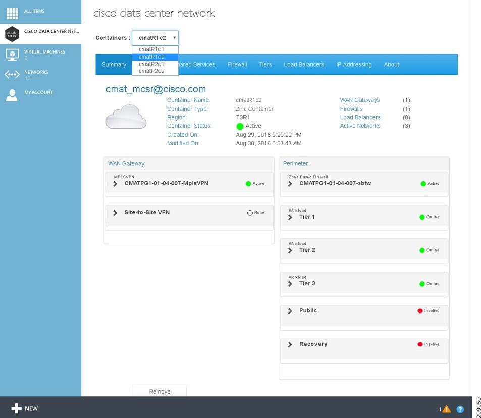
The Tenants Summary screen displays a list of all the WAN Gateway services configured in the container (MPLS VPN, Site-to-Site, Remote Access, and Internet) and a list of all the perimeter network services configured in the container (firewall, tiers, DMZ, etc.).
Specific information above the WAN Gateway and Perimeter tables includes:
- Container Name:—Displays the container name.
- Container Type:—Displays the container type name.
- Hosting Cloud:—Displays the Hosting Cloud name.
- Status:—Displays the container status. The icons indicate (icons are only meaningful on initial configuration as status is not routinely monitored):
–![]() Yellow—Container state is Creating.
Yellow—Container state is Creating.
- Created On:—Displays the date and time when the container was created.
- Modified On:—Displays the date and time when the container was last modified.
- WAN Gateways—Displays the total count of WAN gateways. For example, if MPLS VPN and Site-to-Site were part of the container, the displayed text would be WAN Gateways (2). The icon indicates the status of the WAN Gateway(s): Green, Red, and Gray (icons are only meaningful on initial configuration as status is not routinely monitored).
- Firewalls—Displays the total count of firewalls. For example, if one firewall was part of the container, the displayed text would be Firewalls (1). The icon indicates the status of the firewall(s): Green, Red, and Gray (icons are only meaningful on initial configuration as status is not routinely monitored).
- Load Balancers—Displays the total count of Load Balancers. For example, if two tiers have an SLB, the displayed text would be Load Balancers (2). The current release only supports one tier. The icon indicates the status of the load balancer(s): Green, Red, and Gray (icons are only meaningful on initial configuration as status is not routinely monitored).
- Active Networks—Displays the total count of active networks configured on the container. For example, if there were five total networks, the displayed text would be Active Networks (5).
You can collapse and expand the table information using the triangles, as shown in the following sample screen for the MPLS VPN WAN Gateway and Perimeter Tier 1.
Figure 2-2 Summary Tab—WAN Gateway MPLS VPN Details
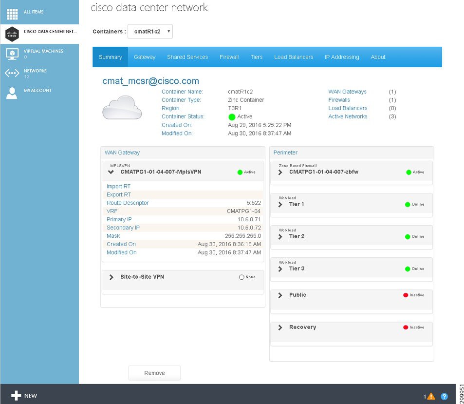
Using MPLS VPN as an example, the information in the WAN Gateway table includes:
- MPLSVPN and name—Gateway type, name of the gateway, and an icon to indicate the status of the VPN (icons are only meaningful on initial configuration as status is not routinely monitored).
- Import RT—The configured RT for the WAN Gateway.
- Export RT—The configured RT for the WAN Gateway.
- Route Descriptor—The configured descriptor based on your cloud provider's network design.
- VRF—Generated by Cisco CNAP based on the abbreviation of the container ID.
- Primary IP—External PE IP Address in dotted format.
- Secondary IP—External PE IP Address in dotted format.
- Mask—External PE Mask in dotted format
- Created On:—Displays the date and time when the WAN Gateway was created.
- Modified On:—Displays the date and time when the WAN Gateway was last modified.
Information in the Perimeter table is based on the currently selected Cloud Service and includes information about firewalls and tiers (in the current release, public for backups and recovery for DMZ are not used).
Figure 2-3 Summary Tab—Perimeter Firewall Details
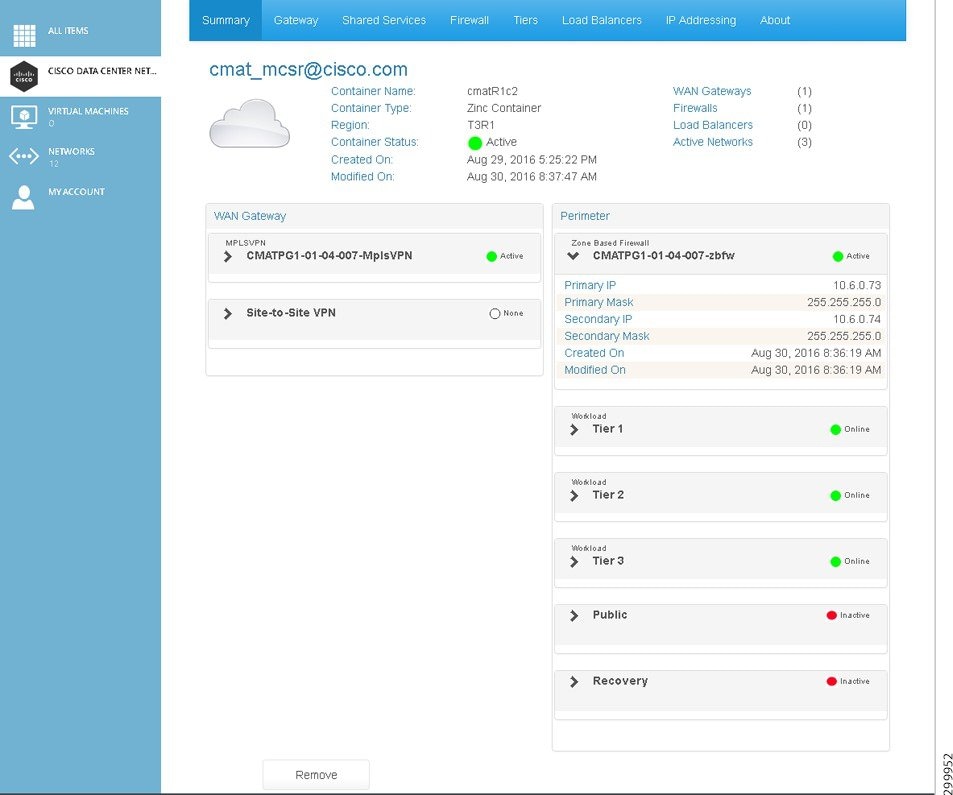
Using Zone Based Firewall as an example, the information in the Perimeter table includes:
- Zone Based Firewall and name—Firewall type, name of the firewall, and an icon to indicate the status of the firewall (icons are only meaningful on initial configuration as status is not routinely monitored).
- Primary IP—External PE IP Address
- Primary Mask—External PE Mask
- Secondary IP—External PE IP Address
- Secondary Mask—External PE Mask
- Created On:—Displays the date and time when the firewall was created.
- Modified On:—Displays the date and time when the firewall was last modified.
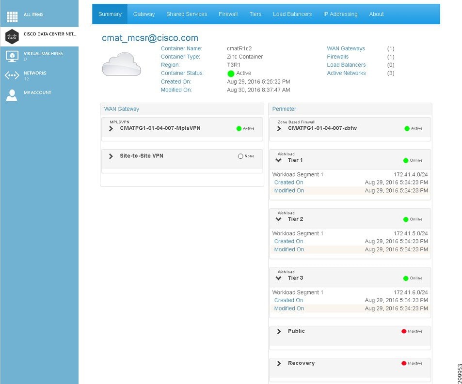
Figure 2-4 Summary Tab—Perimeter Tier Details
Deleting a Container

Note![]() When you delete a container, all information about the container is deleted from the Cisco CNAP database and none of the deleted information can be recovered.
When you delete a container, all information about the container is deleted from the Cisco CNAP database and none of the deleted information can be recovered.
Step 1![]() To display summary information about a specific container instance, click Cisco Datacenter Network.
To display summary information about a specific container instance, click Cisco Datacenter Network.
You see the Tenant Summary Tab screen.
Figure 2-5 Tenant Summary Tab Screen
Step 2![]() You can use the Containers: pull-down menu to select a different container to delete. To delete the selected container, at the bottom of the screen click Remove.
You can use the Containers: pull-down menu to select a different container to delete. To delete the selected container, at the bottom of the screen click Remove.
You see a screen asking you to confirm the deletion, as shown in the following screen.
Figure 2-6 Confirm Container Deletion
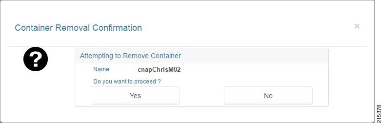
Step 3![]() Click Yes to delete the container or No to cancel the deletion.
Click Yes to delete the container or No to cancel the deletion.
Viewing Gateway Information about a Container
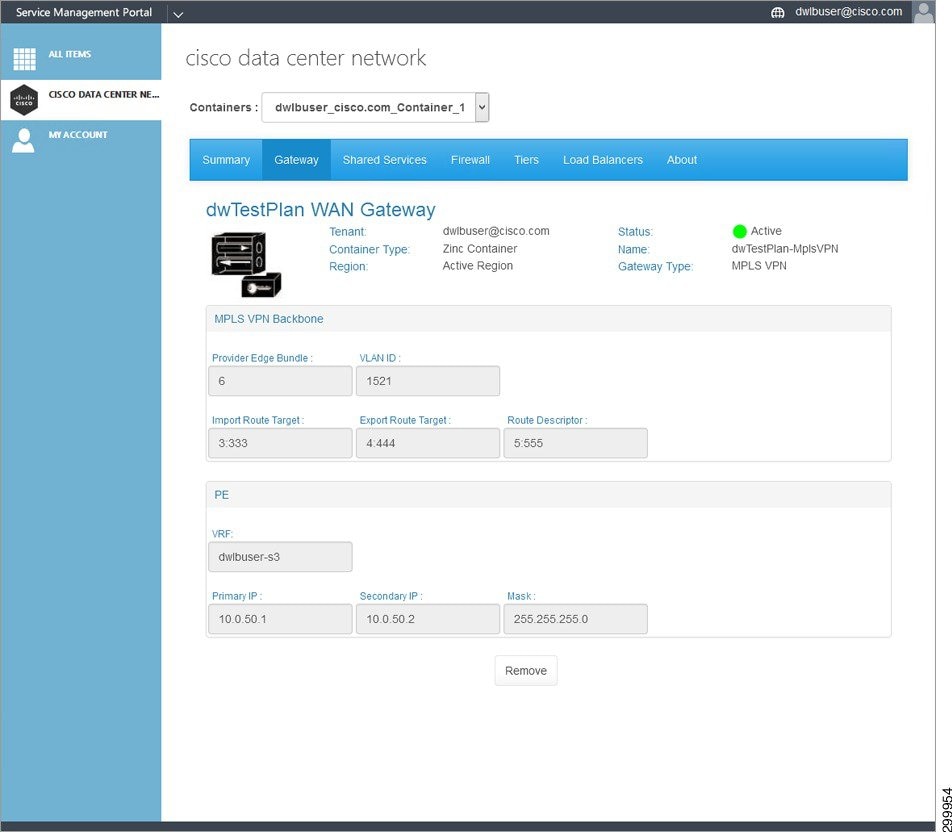
Step 1![]() To view gateway information for the currently selected container, click the Gateway tab.
To view gateway information for the currently selected container, click the Gateway tab.
You see the Tenant Gateway screen. The screen below shows an example for MPLS.
Figure 2-7 Tenant Gateway Tab Screen—MPLS
You can perform the following operation on the gateway screen:
The screen displays the following information:
- Tenant:—Displays the tenant name.
- Container Type:—Displays the container type name, which in the current release is limited to Zinc.
- Hosting Cloud:—Displays the Hosting Cloud name.
- Status:—Displays the WAN Gateway status. The icons indicate (icons are only meaningful on initial configuration as status is not routinely monitored):
–![]() Green—WAN Gateway is Active.
Green—WAN Gateway is Active.
–![]() Red—WAN Gateway is Inactive.
Red—WAN Gateway is Inactive.
–![]() Yellow—WAN Gateway state is Creating.
Yellow—WAN Gateway state is Creating.
- Name:—Displays the name in the form <abbreviation>-mpls-vpn.
- Gateway Type:—MPLS VPN
- Description:—Descriptive name.
- MPLS VPN Backbone:
–![]() Aut. System Number—The PEaciL2InterfacePrimary field from the global settings (contact your cloud provider for more information about this field).
Aut. System Number—The PEaciL2InterfacePrimary field from the global settings (contact your cloud provider for more information about this field).
–![]() Import Route Target—Configured RT for the WAN Gateway.
Import Route Target—Configured RT for the WAN Gateway.
–![]() Export Route Target—Configured RT for the WAN Gateway.
Export Route Target—Configured RT for the WAN Gateway.
–![]() Route Descriptor—Configured descriptor based on your cloud provider's network design.
Route Descriptor—Configured descriptor based on your cloud provider's network design.
–![]() VRF—Generated by Cisco CNAP based on the abbreviation of the container ID.
VRF—Generated by Cisco CNAP based on the abbreviation of the container ID.
–![]() Primary IP—External PE IP Address in dotted format.
Primary IP—External PE IP Address in dotted format.
–![]() Secondary IP—External PE IP Address in dotted format.
Secondary IP—External PE IP Address in dotted format.
–![]() Mask—External PE Mask in dotted format
Mask—External PE Mask in dotted format
Step 2![]() If the WAN Gateway has not been activated, you see the following screen.
If the WAN Gateway has not been activated, you see the following screen.
Figure 2-8 Gateway Tab—WAN Gateway Not Activated
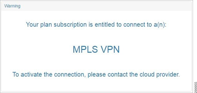
Step 3![]() Contact your cloud provider to have the WAN Gateway activated.
Contact your cloud provider to have the WAN Gateway activated.
Removing a WAN Gateway
Viewing and Modifying Access to Shared Services
If your cloud provider has configured access to Shared Services, such as Database as a Service (DBaaS), Disaster Recovery as a Service (DRaaS), etc., those Shared Services will be displayed when you are creating a container for a plan to which you have subscribed.
Viewing Information about Shared Services
To view information about Shared Services:
Step 1![]() Click the Shared Services tab.
Click the Shared Services tab.
Figure 2-9 Shared Services Tab
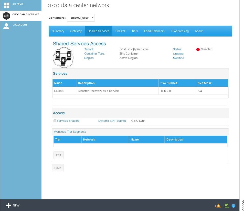
This screen displays the following fields:
- Tenant:—Displays the tenant name.
- Container Type:—Displays the container type instance name.
- Hosting Cloud:—Displays the Hosting Cloud name.
- Status:—Displays the Shared Services Access status. The icons indicate (icons are only meaningful on initial configuration as status is not routinely monitored):
- Created:—Displays the date and time when access was activated in the form.
- Modified:—Displays the date and time when access was last modified in the form.
- Services:
–![]() Name— Name given to the Shared Service at the time the service was onboarded.
Name— Name given to the Shared Service at the time the service was onboarded.
–![]() Description—Brief description of the Shared Service.
Description—Brief description of the Shared Service.
–![]() Svc Subnet— IP subnet (Public) on which the Shared Service is available.
Svc Subnet— IP subnet (Public) on which the Shared Service is available.
–![]() Svc Mask— Subnet Mask associated with the Shared Service subnet.
Svc Mask— Subnet Mask associated with the Shared Service subnet.
–![]() Services Enabled—Indicates whether Shared Services are enabled.
Services Enabled—Indicates whether Shared Services are enabled.
–![]() Dynamic NAT Subnet—The associated NAT subnet.
Dynamic NAT Subnet—The associated NAT subnet.
–![]() Description—The segment description.
Description—The segment description.
Enabling Access to Shared Services
To enable access to Shared Services:
Step 1![]() Click the Shared Services tab.
Click the Shared Services tab.
You see the following screen, which lists the available Shared Services.
Figure 2-10 Enabling Access to Shared Services
Step 2![]() Click the check box next to Services Enabled and click Edit.
Click the check box next to Services Enabled and click Edit.
Figure 2-11 Select Tier Segments with Access to Shared Services
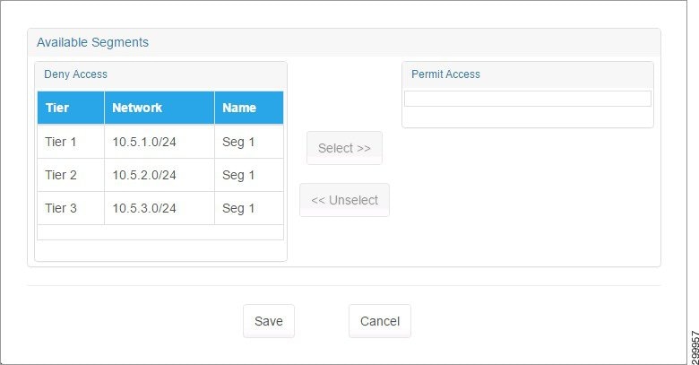
Step 3![]() Click a tier segment you want to have access to Shared Services, then click Select>>. Select additional tier segments in the same way, as shown in the following screen.
Click a tier segment you want to have access to Shared Services, then click Select>>. Select additional tier segments in the same way, as shown in the following screen.
Figure 2-12 Tier Segments Selected
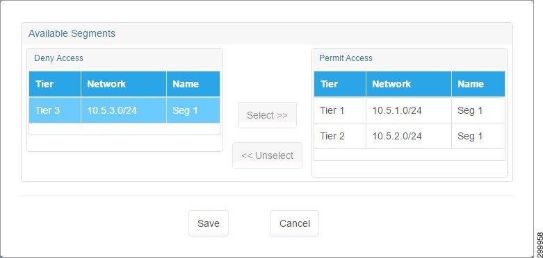
Step 4![]() When you are finished selecting tier segments, click Save.
When you are finished selecting tier segments, click Save.
You return to the Shared Service tab screen with the selected tiers displayed under Workload Tier Segments, as shown in the following screen.
Figure 2-13 Shared Services Tab with Access Enabled for Tier Segments
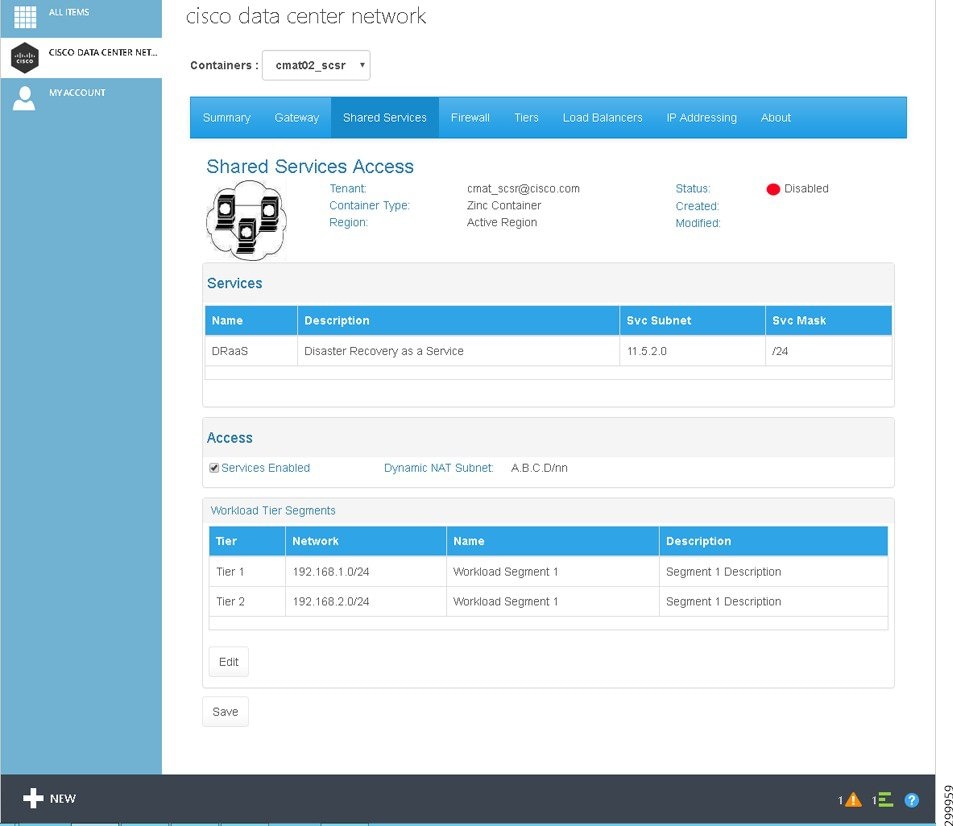
Step 5![]() The tier segments do not have access until you click Save.
The tier segments do not have access until you click Save.
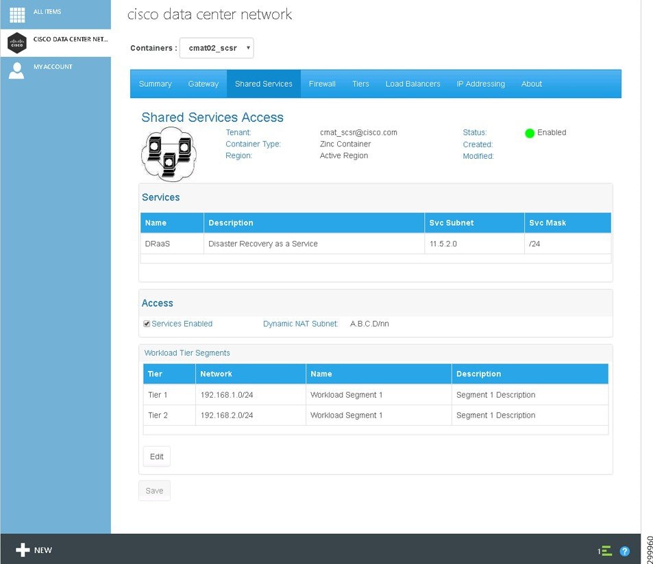
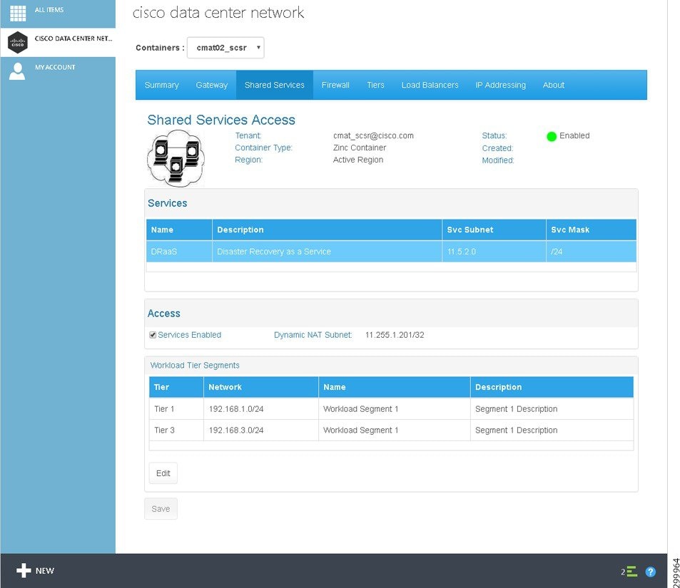
The configuration takes a few moments. When you refresh the screen, you see that the Status: is now Enabled. If you click on a specific Shared Services, the Dynamic NAT Subnet: field will update, as shown in the following screen. The Dynamic NAT Subnet is configured by your cloud provider.
Figure 2-14 Shared Services Access Enabled
Changing Access to Shared Services
You can change and add access rights for tier segments.
To change access to Shared Services:
Step 1![]() Click the Shared Services tab.
Click the Shared Services tab.
You see the following screen, which lists the available Shared Services.
Figure 2-15 Changing Access to Shared Services
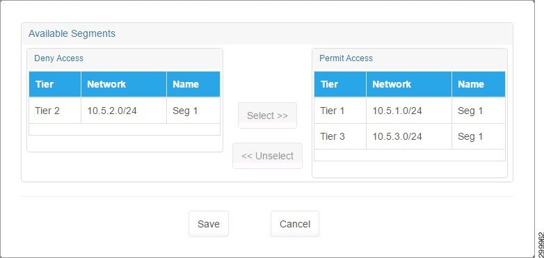
Figure 2-16 Tier Segments with Access to Shared Services
Step 3![]() You can remove and add access to tier segments by clicking a tier segment then clicking Select>> or <<Unselect to move tier segments between Deny Access and Permit Access. In the following screen, Tier 2 has been moved to Deny Access and Tier 3 to Permit Access.
You can remove and add access to tier segments by clicking a tier segment then clicking Select>> or <<Unselect to move tier segments between Deny Access and Permit Access. In the following screen, Tier 2 has been moved to Deny Access and Tier 3 to Permit Access.
Figure 2-17 Tier Segments Selected and Access Rights Changed
Step 4![]() When you are finished selecting tier segments, click Save.
When you are finished selecting tier segments, click Save.
You return to the Shared Service tab screen with the tiers displayed under Workload Tier Segments, as shown in the following screen.
Figure 2-18 Shared Services Tab with Access Changed for Tier Segments
Step 5![]() The changes to the tier segments are not effective until you click Save.
The changes to the tier segments are not effective until you click Save.
The configuration takes a few moments. When you refresh the screen, you see that the Status: is now Enabled. If you click on a specific Shared Services, the Dynamic NAT Subnet: field will update, as shown in the following screen.
Figure 2-19 Changed Shared Services Access Enabled
Disabling Access to Shared Services
To disable access to Shared Services:
Step 1![]() Click the Shared Services tab.
Click the Shared Services tab.
You see the following screen, which lists the available Shared Services.
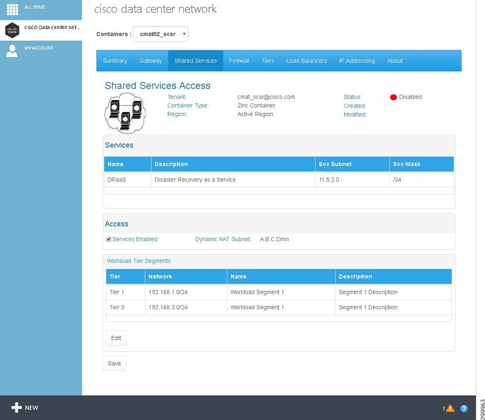
Figure 2-20 Access to Shared Services
Step 2![]() You can disable access to Shared Services in two ways:
You can disable access to Shared Services in two ways:
- Click Edit. On the pop-up menu, select the tier segments under Permit Access and use the <<Unselect button to move them all to Deny Access, then click Save. Also click Save on the main Shared Services tab screen.
- On the main Shared Services tab screen, remove the check mark from Service Enabled, then click Save.
Figure 2-21 Confirm Disable Access to Shared Services
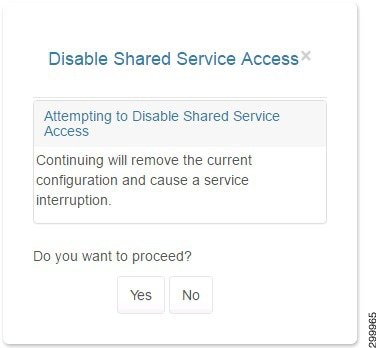
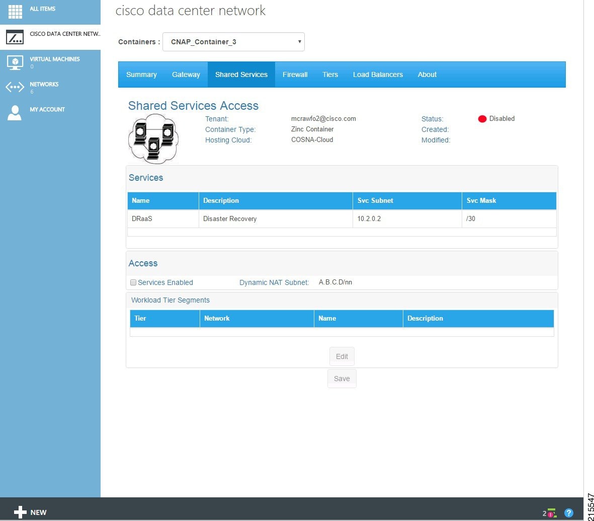
The configuration takes a few moments. When you refresh the screen, you see that the Status: is now Disabled and the tiers no longer display under Workload Tier Segments, as shown in the following screen.
Figure 2-22 Shared Services Access Disabled
Viewing and Modifying Firewall Information about a Container
Understanding Firewall Creation
A firewall is created by default the moment your cloud provider creates a WAN Gateway. Cisco CNAP will automatically set up a perimeter around each of the zones in your container. Each Tier is considered a zone, as is the Layer 3 VPN as well as any other external access such as Site-to-Site VPN, Internet access, etc. The Firewall tab will not display any information until the WAN Gateway has been provisioned, since there is no point in showing how traffic is going to be regulated if you cannot access the container from the “outside”.
For detailed information on the base firewall configuration, see: Cisco Cloud Architecture for the Microsoft Cloud Platform: Zinc Container Configuration Guide, Release 1.0
http://www.cisco.com/c/en/us/td/docs/solutions/Service_Provider/CCAMCP/1-0/IaaS_Zinc_Config/CCAMCP1_IaaS_Zinc_Config.html
Viewing Summary Information about a Firewall
Step 1![]() To view firewall information, click the Firewall tab.
To view firewall information, click the Firewall tab.
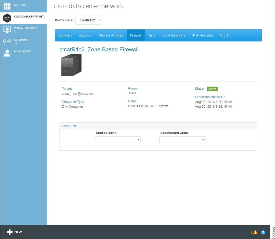
The screen displays the following information:
- Tenant:—Displays the tenant name.
- Container Type:—Displays the container type instance name.
- Hosting Cloud:—Displays the Hosting Cloud name.
- Modified:—Displays the date and time when the firewall was last modified.
- Status:—Displays the firewall status. The icons indicate (icons are only meaningful on initial configuration as status is not routinely monitored):
–![]() Yellow—Firewall state is Creating.
Yellow—Firewall state is Creating.
- Name:—Displays the name in the form < abbreviation >-fw.
- Created:—Displays the date and time when the firewall was created.
- Zone Pair—Source Zone and Destination Zone are the zones between which the firewall is configured.
Viewing the Hierarchy of Information on the Firewall Tab
You use the Firewall Tab to view the various layers of information about firewalls, including:
Note![]() To change the Policy Map associated with a Source and Destination Zone pair, you have to define a new Policy Map, which replaces the existing one.
To change the Policy Map associated with a Source and Destination Zone pair, you have to define a new Policy Map, which replaces the existing one.
- Class Maps in a Service Policy
- Access Control Lists within a Class Map
- Rules in an Access Control List
- Object Groups of a Rule
To display the various tiers of information about a firewall:
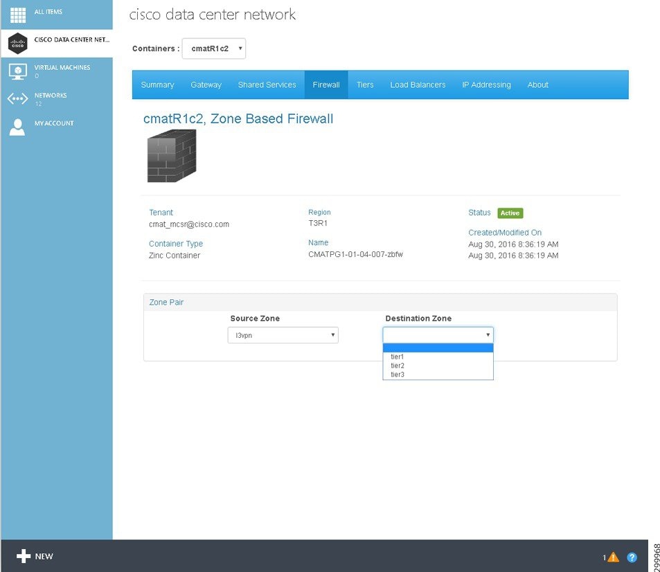
Step 1![]() Use the Source Zone: and Destination Zone: pull-down menus to select the relevant zones, as shown in the following screens.
Use the Source Zone: and Destination Zone: pull-down menus to select the relevant zones, as shown in the following screens.
Figure 2-24 Firewall Source Zone Pull-down Menu
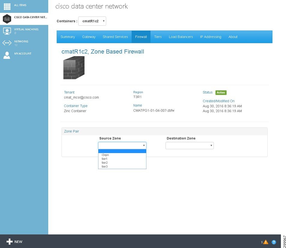
Figure 2-25 Firewall Destination Zone Pull-down Menu
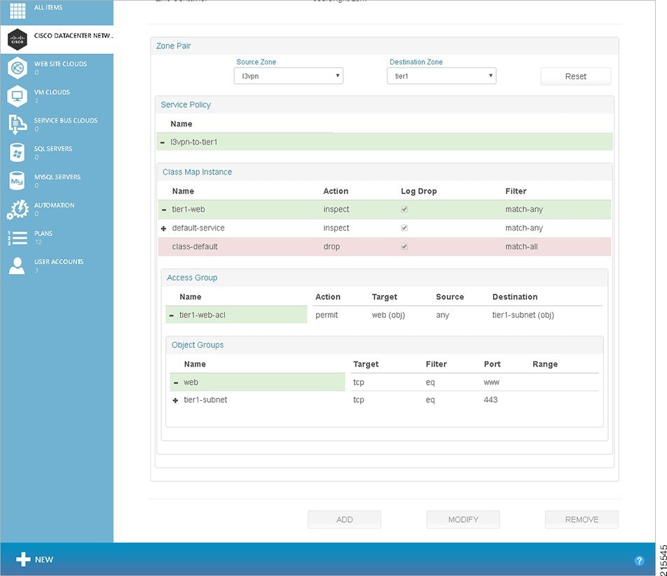
After you select the Source and Destination Zones, the screen populates with a variety of information, as shown in the following screen.
Figure 2-26 Firewall Zones Selected Screen—Detailed Firewall Information Displayed
The various operations you can perform on this screen are described in the following section, Configuring a Firewall.
Step 2![]() If you click an element on the screen to bring it into focus, it changes to blue. For the element in focus:
If you click an element on the screen to bring it into focus, it changes to blue. For the element in focus:
- The Remove button de-couples the entity in focus, for example the Class Map Instance tier1-web, from the parent entity marked, for example the Policy Map l3vpn-to-tier1 for the Service Policy.
The Remove button may be used to remove a:
–![]() Class Map Instance from a Policy Map
Class Map Instance from a Policy Map
–![]() Access List from a Class Map
Access List from a Class Map
Note![]() In the current release, Cisco CNAP allows and requires you to associate only one Policy Map with any given zone pair. Consequently, the Remove button is deactivated when you drill down to the Policy Map, but not further.
In the current release, Cisco CNAP allows and requires you to associate only one Policy Map with any given zone pair. Consequently, the Remove button is deactivated when you drill down to the Policy Map, but not further.
Configuring a Firewall
Note![]() You can only configure a firewall after you have created a container and your cloud provider has created a WAN Gateway. The firewall is automatically created with a base configuration either during container creation if the container has multiple tiers or when the WAN gateway is created. For more information, see the section Understanding Firewall Creation.
You can only configure a firewall after you have created a container and your cloud provider has created a WAN Gateway. The firewall is automatically created with a base configuration either during container creation if the container has multiple tiers or when the WAN gateway is created. For more information, see the section Understanding Firewall Creation.
Firewalls are configurable on a per-Tier basis. You configure one firewall per container (not per tier) and you specify policy rules between zones. Firewall policies are specified between each of the workload Tiers and outside interfaces and in each direction independently. That is, a policy needs to be specified for L3VPN to Tier 1 and Tier 1 to L3VPN, and so on for each tier.
To configure a firewall for a container:
Step 1![]() Use the Source Zone: and Destination Zone: pull-down menus to select the relevant zones. After you select the zones, the screen populates with a variety of information, as shown in the following screen.
Use the Source Zone: and Destination Zone: pull-down menus to select the relevant zones. After you select the zones, the screen populates with a variety of information, as shown in the following screen.
Figure 2-27 Firewall Zones Selected Screen—Detailed Firewall Information Displayed
Step 2![]() To add a Policy Map, click the Policy Map under Service Policy, then click the Add button. You see the following screen.
To add a Policy Map, click the Policy Map under Service Policy, then click the Add button. You see the following screen.
Figure 2-28 Add Policy Map for Service Policy Screen
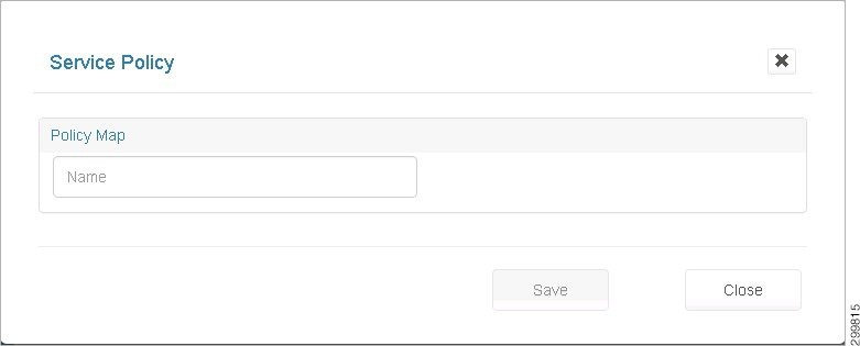
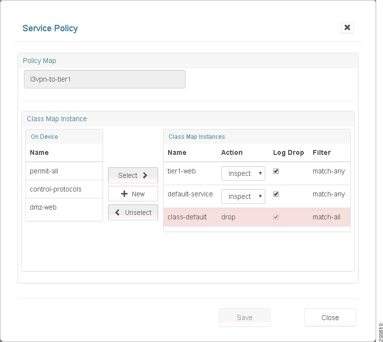
As you begin entering a name, the screen expands to display the following screen where you can associate class maps with the new Policy Map.
Figure 2-29 New Policy Map—Class Maps Screen
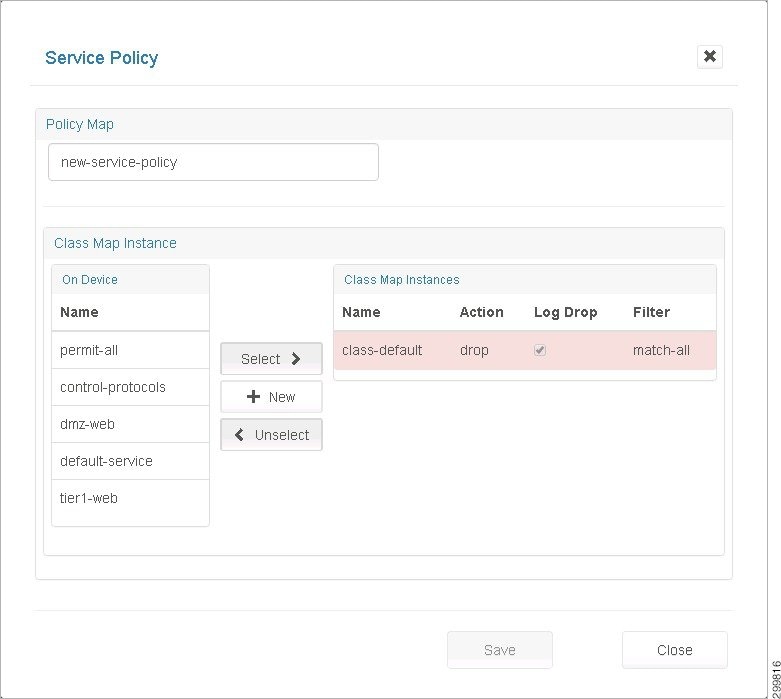
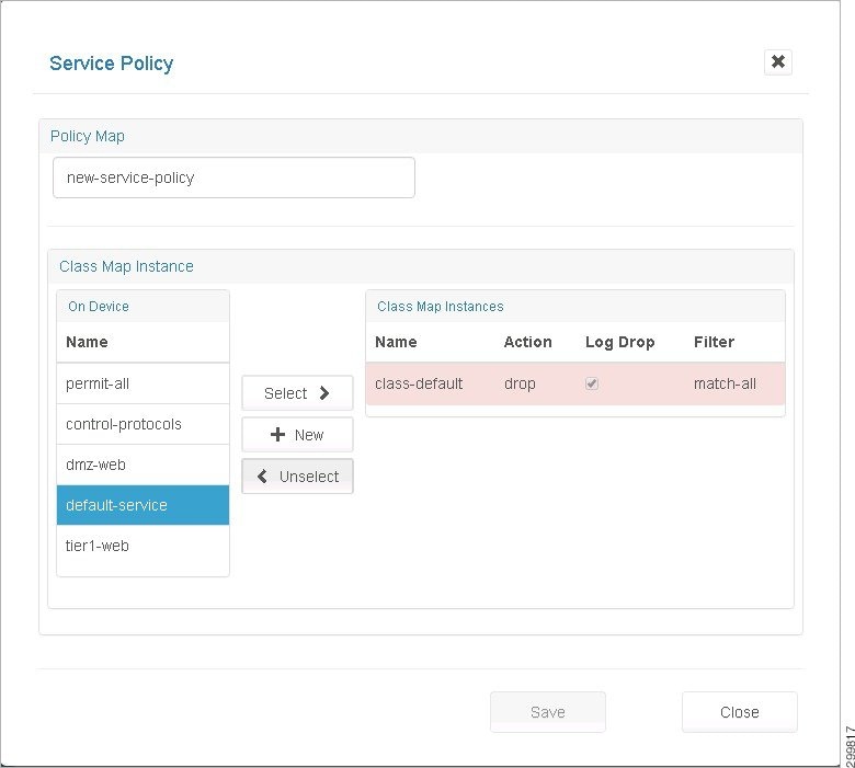
Step 4![]() Associate class maps with the new Policy Map:
Associate class maps with the new Policy Map:
- Name—Enter a descriptive name for the Policy Map.
- On Device—Lists all the Class Maps available on the device.
- Class Map Instances—Lists the class maps associated with this Policy Map.
- Select>> button—Click to select one or more Class Maps available “On Device”'. Clicking Select associates them to the current Policy Map.
- <<Unselect button—Click to select one or more Class Map Instances associated with the current Service Policy. Clicking Unselect disassociates them from the current Policy Map.
- +New button—Click the + New button to create a new Class Map.
- Ordering the Class Maps—The Class Map Instances get added to the top of the list. You can reorder them by clicking <<Unselect and Select>> on the Class Maps in the desired order.
Note![]() The class-default shown in the following screen cannot be de-coupled from the policy.
The class-default shown in the following screen cannot be de-coupled from the policy.
Figure 2-30 Class Map Instance class-default Screen
Step 5![]() When you are finished, click Save.
When you are finished, click Save.
Changing a Policy Map for a Service Policy
Step 1![]() Click a Policy Map to select it (mark it blue).
Click a Policy Map to select it (mark it blue).
Step 2![]() Click the Modify button to display the Policy Map pop-up.
Click the Modify button to display the Policy Map pop-up.
Figure 2-31 Policy Map Pop-up Screen
This is the same as the Create Service Policy page, but with the name field deactivated. You can click:
- Select>> to select Class Maps available on the device.
- <<Unselect to unselect Class Map Instances associated with the Policy Map.
- +New to create a new Class Map.
Adding a New Class Map
Step 1![]() Click + New in the Class Map Instance section on the Policy Map screen shown below.
Click + New in the Class Map Instance section on the Policy Map screen shown below.
Figure 2-32 Class Map Instance Screen—Click +New
Figure 2-33 New Class Map Instance Screen
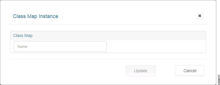
Step 2![]() In the Name field, enter a descriptive name for your new Class Map.
In the Name field, enter a descriptive name for your new Class Map.
This expands the screen to display the following screen.
Figure 2-34 New Class Map Instance Details Screen
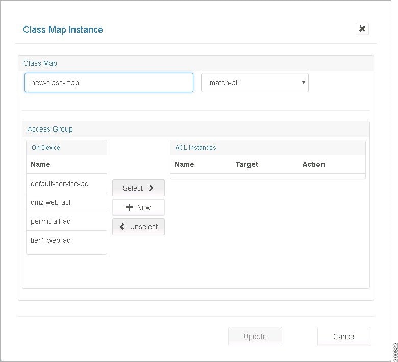
The fields on this screen are:
- match-all/match-any—This pull-down menu identifies the criteria used to match access groups in the map.
- On Device—Lists all the ACLs available for use on the device.
- ACL Instances—Lists the ACLs associated with this Class Map.
- Select>>, + New, and <<Unselect —These buttons work the same as on the Service Policy screen.
Step 3![]() When you are finished associating ACLs to this Class Map, click Update to return to the Service Policy screen.
When you are finished associating ACLs to this Class Map, click Update to return to the Service Policy screen.
Changing a Class Map
Step 1![]() Select the desired Class Map on the Firewall tab.
Select the desired Class Map on the Firewall tab.
Figure 2-35 Class Map Instance Screen
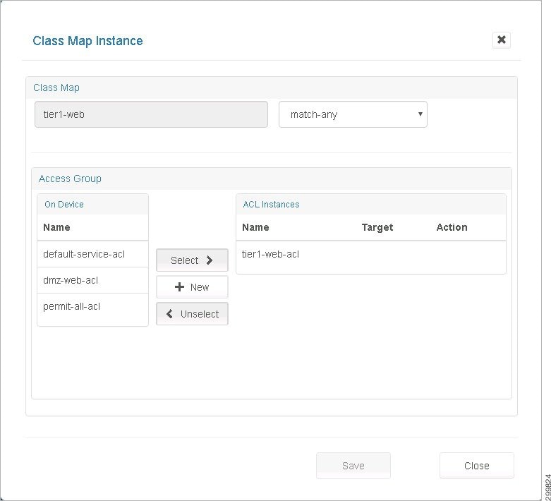
This screen is identical to the Create Class Map pop up, but with the Name field deactivated.
- Select>> ACLs from the list of ACLs available on the device.
- <<Unselect ACLs associated with the Class Map.
- Create a + New ACL on the device and have it associated with the Class Map.
Creating a New Network Access Control List
Step 1![]() Click New on the Class Map Instance screen shown above, which displays the Access Group screen shown below.
Click New on the Class Map Instance screen shown above, which displays the Access Group screen shown below.
Figure 2-36 Access Groups Screen
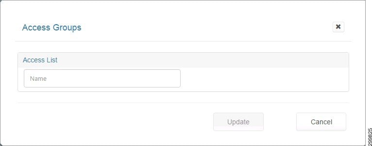
Step 2![]() When you enter a name for the Access List, the screen expands to display the Rules section. Since this is a new ACL, the screen expands in the Add Rule mode as shown below.
When you enter a name for the Access List, the screen expands to display the Rules section. Since this is a new ACL, the screen expands in the Add Rule mode as shown below.
Figure 2-37 Access Groups Details Screen
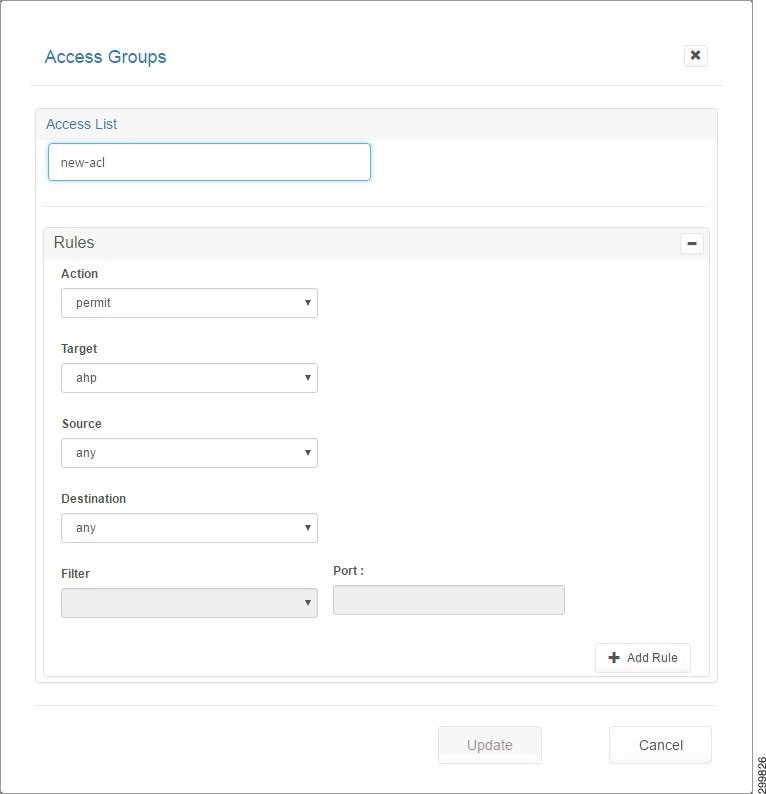
Step 3![]() The fields you can complete include:
The fields you can complete include:
- Action—Indicates weather traffic is permitted or denied by the rule.
- Target—A valid protocol or object group.
- Source—Network entity identified as the traffic source.
- Destination—Network entity identified as the traffic destination.
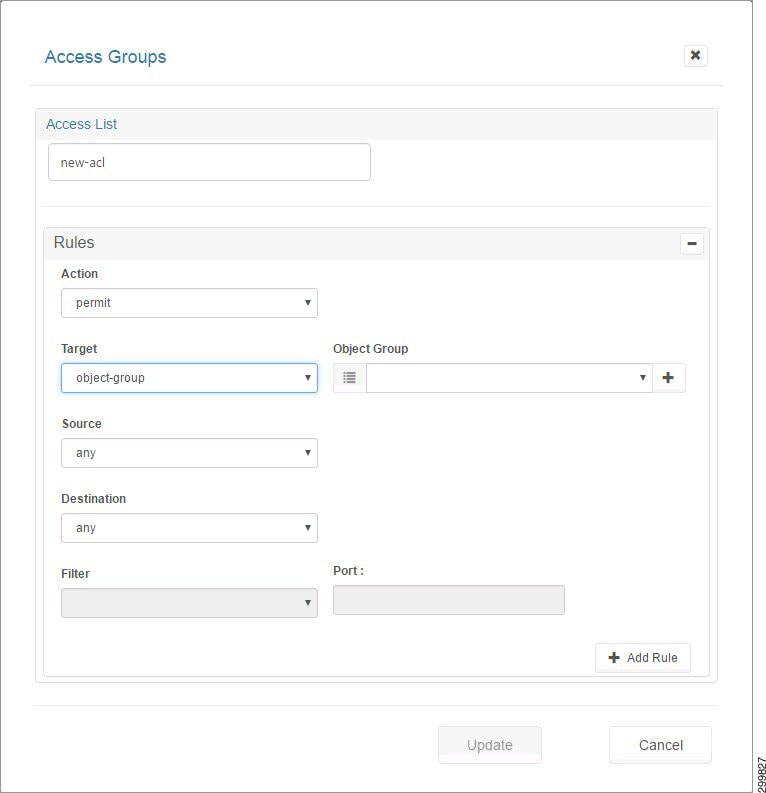
Step 4![]() If you select Object-Group in the drop-down menu for Target, the Source or Destination menus allow you to choose from object groups existing on the device or create new ones, as shown in the following screen.
If you select Object-Group in the drop-down menu for Target, the Source or Destination menus allow you to choose from object groups existing on the device or create new ones, as shown in the following screen.
Figure 2-38 Access Groups Screen—Object Group Selected
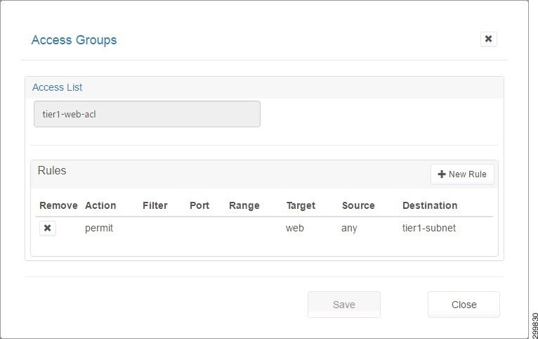
Step 5![]() Click the +Add Rule button to add the current rule being built to the ACL.
Click the +Add Rule button to add the current rule being built to the ACL.
Figure 2-39 Rule Added to ACL Screen
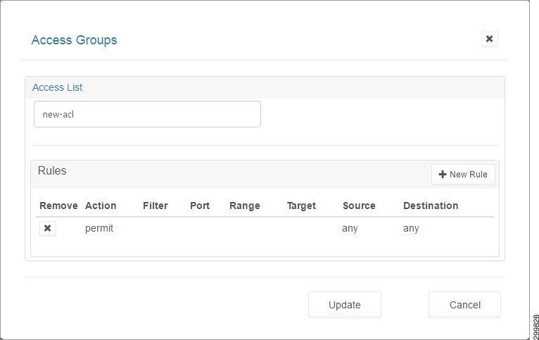
Step 6![]() Click +New Rule to add more rules.
Click +New Rule to add more rules.
Step 7![]() Click the Update button to exit the Add Rule mode and show the list of all rules in the ACL.
Click the Update button to exit the Add Rule mode and show the list of all rules in the ACL.
Changing an Access List
Step 1![]() Select the desired Access List on the Firewall tab.
Select the desired Access List on the Firewall tab.
Step 2![]() Click Modify to display the Access List pop-up screen, as shown below.
Click Modify to display the Access List pop-up screen, as shown below.
Figure 2-40 Access List Pop-up Screen
Step 3![]() You can add and remove rules as explained in Creating a New Network Access Control List.
You can add and remove rules as explained in Creating a New Network Access Control List.
Step 4![]() If you make any changes to the list of Rules, the Save button is activated and you can click it to save the changes.
If you make any changes to the list of Rules, the Save button is activated and you can click it to save the changes.
Creating a New Object Group
Step 1![]() Select the desired Access List on the Firewall tab.
Select the desired Access List on the Firewall tab.
Step 2![]() Click Modify to display the Access List pop-up screen, as shown in the following screen.
Click Modify to display the Access List pop-up screen, as shown in the following screen.
Figure 2-41 Access List Pop-up Screen
Step 3![]() Click the +New Rule button.
Click the +New Rule button.
On the Access Groups screen, the Target, Source, and Destination drop-down menus have an object-group option which when selected displays the Object Group: fields with drop-down menus with a list of compatible object groups and + buttons that launch a page where you can create a new compatible Object Group.
- The Object Group drop-down menu for Target would only show Service type Object Groups (groups of objects having the Target, filter, and port fields or having the Target and Range fields).
- The Object Group drop down for Source and Destination would only show Network type Object Groups (groups of objects having a Host field or having the Subnet and mask fields).
- The + buttons are contextual. Clicking the + button for the Target of the ACL Rule launches a page to create an Object Group with Service type objects.
- Clicking the + button for the Source or Destination of the ACL Rule launches a page to create an Object Group with Network type objects.
Step 4![]() Click the + button as shown in the following screen.
Click the + button as shown in the following screen.
Figure 2-42 Access Groups Screen—Object Group Selected
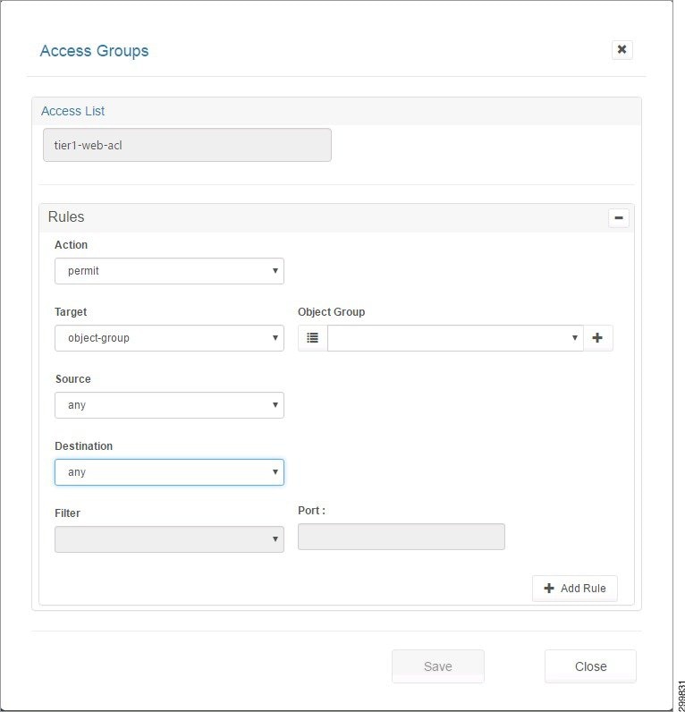
Figure 2-43 Object Group Screen
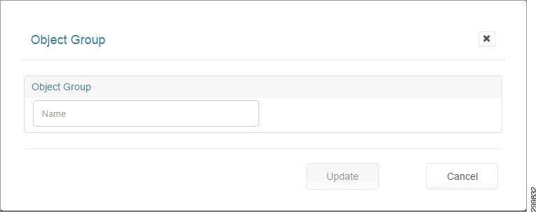
Step 5![]() When you enter a name, you see the Add Object screen, as shown below.
When you enter a name, you see the Add Object screen, as shown below.
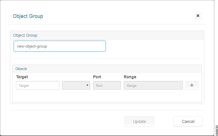
Step 6![]() When you click a field, you see information about allowable values, as shown in the following screen.
When you click a field, you see information about allowable values, as shown in the following screen.
Figure 2-45 Add Object Screen—Possible Field Values Displayed
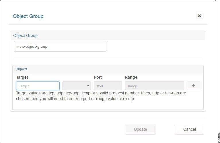
Step 7![]() You can enter information for the following fields:
You can enter information for the following fields:
- Target—A valid protocol {ahp, esp, gre, icmp, ip, tcp, udp, number [0,255]}.
- Filter—eq (equals), gt (greater than), or lt (less than). The Filter indicates the criteria to match packets based on the port number. If “filter” is present, then “port” must be present.
- Port—IP port [0,65535]
- Range—<port-number1>-<port-number2>. Must be entered from low to high, e.g., 20-90. Match only packets in the range of the port numbers.
Note![]() If “range” is present, the “filter” and “port” properties are ignored.
If “range” is present, the “filter” and “port” properties are ignored.
Step 8![]() You can create Network or Service type objects and click + to include the object in the group.
You can create Network or Service type objects and click + to include the object in the group.
A Group must be homogeneous; i.e., it must contain objects of only one type (Network or Service)
Step 9![]() When you click +, you see the following screen.
When you click +, you see the following screen.
Figure 2-46 Object Added to Group Screen
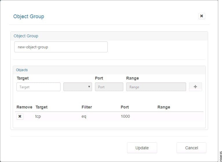
Step 10![]() Click the X under Remove to remove an object from the group.
Click the X under Remove to remove an object from the group.
Changing an Object Group
Step 1![]() On the screen shown below, select the object group you want to change, then click Modify.
On the screen shown below, select the object group you want to change, then click Modify.
Figure 2-47 Firewall Zones Selected Screen—Select Object Group
Figure 2-48 Modify Object Group Screen
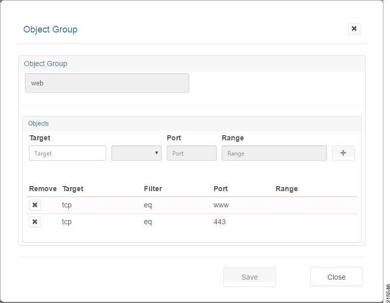
Step 2![]() You can enter information for the following fields:
You can enter information for the following fields:
- Target—A valid protocol {ahp, esp, gre, icmp, ip, tcp, udp, number [0,255]}.
- Filter—eq (equals), gt (greater than), or lt (less than). The Filter indicates the criteria to match packets based on the port number. If “filter” is present, then “port” must be present.
- Port—IP port [0,65535]
- Range—<port-number1>-<port-number2>. Must be entered from low to high, e.g., 20-90. Match only packets in the range of the port numbers.
Note![]() If “range” is present, the “filter” and “port” properties are ignored.
If “range” is present, the “filter” and “port” properties are ignored.
Step 3![]() You can create Network or Service type objects and click + to include the object in the group.
You can create Network or Service type objects and click + to include the object in the group.
A Group must be homogeneous; i.e., it must contain objects of only one type (Network or Service)
Step 4![]() When you click +, the object is added to the group. Click the X under Remove to remove an object from the group. When you are done, click Save to save your changes or Close to exit without saving them.
When you click +, the object is added to the group. Click the X under Remove to remove an object from the group. When you are done, click Save to save your changes or Close to exit without saving them.
Viewing and Modifying Tier Information about a Container
Step 1![]() To view tier information, click the Tiers tab.
To view tier information, click the Tiers tab.
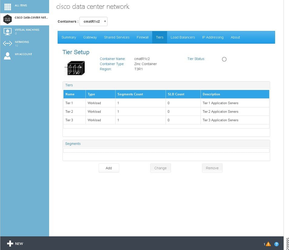
Step 2![]() To view segment information about a specific tier, click the tier name.
To view segment information about a specific tier, click the tier name.
Figure 2-50 Tiers Screen—Tier Selected and Segment(s) Visible
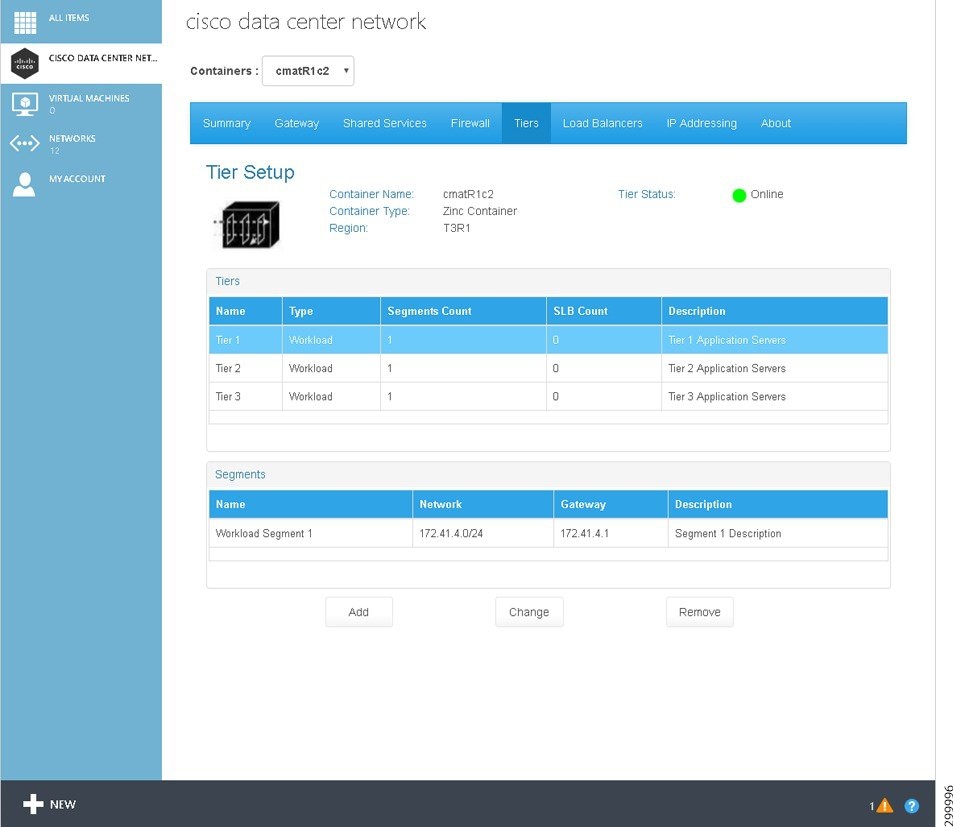
The screen displays the following information:
- Container Name:—Displays the container name.
- Container Type:—Displays the container type instance name.
- Hosting Cloud:—Displays the Hosting Cloud name.
- Name:—Name of the tier.
- Description:—Description of the tier.
- Status:—Displays the Tiers status. The icons indicate (icons are only meaningful on initial configuration as status is not routinely monitored):
–![]() Name—Name given to the tier. The System assigns Tier < space >< number > during container creation.
Name—Name given to the tier. The System assigns Tier < space >< number > during container creation.
–![]() Type—It specifies the type of container to which the tier belongs.
Type—It specifies the type of container to which the tier belongs.
–![]() Num Segments—Tiers can contain multiple segments.
Num Segments—Tiers can contain multiple segments.
–![]() Num SLB—Number of Server Load Balancers
Num SLB—Number of Server Load Balancers
–![]() Description—A brief description of the tier (what the user intends to use it for, what services are hosted in it, etc.)
Description—A brief description of the tier (what the user intends to use it for, what services are hosted in it, etc.)
–![]() Name—Name given to the segment. The System assigns Segment < space >< number > during container creation.
Name—Name given to the segment. The System assigns Segment < space >< number > during container creation.
–![]() Network—The subnet address of this segment.
Network—The subnet address of this segment.
–![]() Gateway—The default gateway to access this segment.
Gateway—The default gateway to access this segment.
–![]() Description—A brief description of the segment (what the user intends to use it for, what services are hosted in it, etc.).
Description—A brief description of the segment (what the user intends to use it for, what services are hosted in it, etc.).
Adding a Tier
Step 1![]() On the Tiers Tab screen, click Add.
On the Tiers Tab screen, click Add.
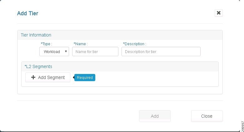
The screen displays the following information:
- Type:—Only Workload is supported in the current release.
- Name:—Enter a name for the tier.
- Description:—Enter a description for the tier.
- Enter L2 Segments—
–![]() Add—Add a segment. For more information, see the next section.
Add—Add a segment. For more information, see the next section.
–![]() Name—Name of the Layer 2 segment.
Name—Name of the Layer 2 segment.
–![]() Sub Net—Subnet of the Layer 2 segment.
Sub Net—Subnet of the Layer 2 segment.
–![]() Description—Description of the Layer 2 segment.
Description—Description of the Layer 2 segment.
Step 2![]() When you are finished, click Add.
When you are finished, click Add.
Adding a Segment
When you are adding a tier, you must add a segment:
Step 1![]() On the Add Tier screen shown in the previous section, under Enter L2 Segments, click the addition symbol (+).
On the Add Tier screen shown in the previous section, under Enter L2 Segments, click the addition symbol (+).
Figure 2-52 Add Segment Screen
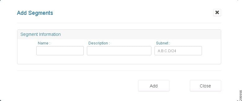
Enter information about the segment:
Step 2![]() When you are finished, click Add.
When you are finished, click Add.
Changing a Tier
Step 1![]() On the Tiers Tab screen, click the tier you want to change, then click Change (when you click a tier, you see segment information about the selected tier).
On the Tiers Tab screen, click the tier you want to change, then click Change (when you click a tier, you see segment information about the selected tier).
Figure 2-53 Change a Tier Screen
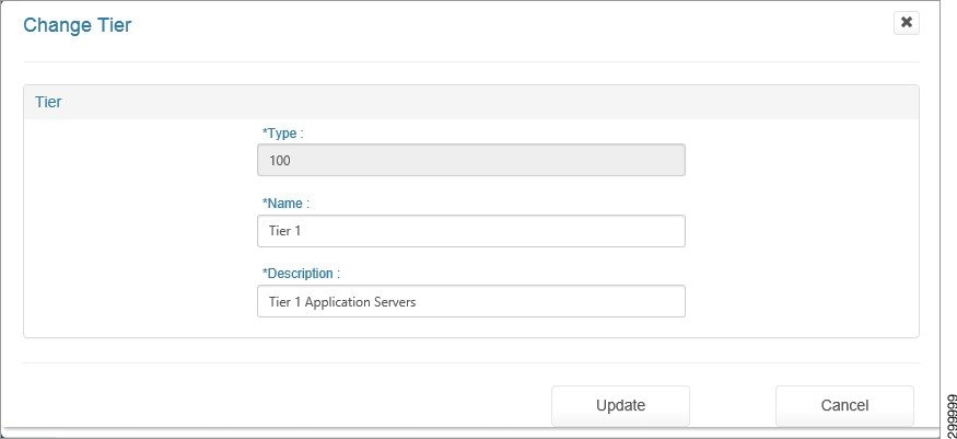
The screen displays the following information, some of which you can change:
–![]() Name:—You can edit the name.
Name:—You can edit the name.
–![]() Description:—You can edit the description.
Description:—You can edit the description.
–![]() Name—Name of the Layer 2 segment.
Name—Name of the Layer 2 segment.
–![]() Description—Description of the Layer 2 segment.
Description—Description of the Layer 2 segment.
–![]() Network—The network of the Layer 2 segment.
Network—The network of the Layer 2 segment.
You can click a specific segment under L2 Segments to update it. For more information, see the next section.
Step 2![]() When you are finished, click Change.
When you are finished, click Change.
Updating a Segment
When you are changing a tier, you can update a segment:
Step 1![]() On the Change Tier screen shown in the previous section, under L2 Segments, click the segment you want to update.
On the Change Tier screen shown in the previous section, under L2 Segments, click the segment you want to update.
Figure 2-54 Update Segments Screen
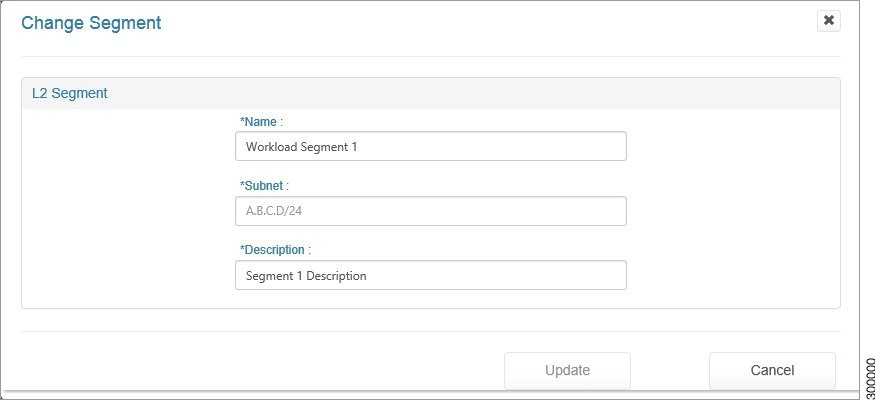
- Name:—You can edit the name of the segment
- Description:—You can edit the description of the segment.
Step 2![]() When you are finished, click Update.
When you are finished, click Update.
You return to the previous screen.
Removing a Tier
To remove a tier, on the Tiers Tab screen, click the tier you want to remove, then click Remove. In the current release, you must return to the Tiers tab to force a reload and consequent fetch from the backend.
Viewing and Modifying Load Balancer Information about a Container
Understanding the Load Balancer Creation Procedure
Creating a load balancer involves three steps:
1.![]() Add a Citrix NetScaler VPX.
Add a Citrix NetScaler VPX.
2.![]() Contact your cloud provider to license the Citrix NetScaler VPX you added.
Contact your cloud provider to license the Citrix NetScaler VPX you added.
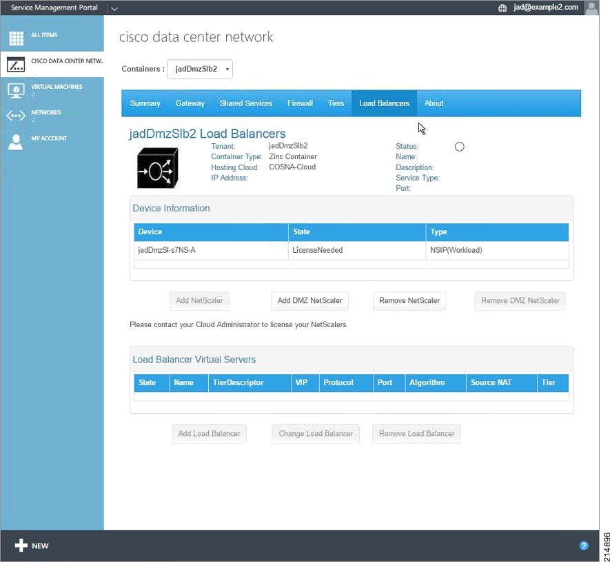
Viewing Load Balancer Information
Load balancing services are performed on a per-tenant container basis, so you can view information about a load balancer, such as the associated tenant, container type, hosting cloud, etc.
Step 1![]() If a load balancer has been created, to view information about it, click the Load Balancers tab.
If a load balancer has been created, to view information about it, click the Load Balancers tab.
Figure 2-55 Load Balancers Tab
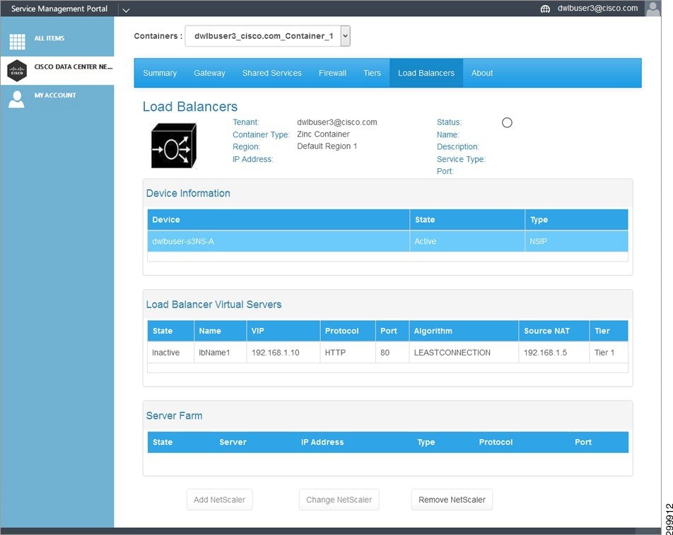
If you click a specific Load Balancer Virtual Server, you see the corresponding Server Farm.
The screen displays the following information:
- Tenant:—Displays the tenant name.
- Container Type:—Displays the container type name.
- Hosting Cloud:—Displays the Hosting Cloud name.
- IP Address:—Displays the IP address of the load balancer.
- Status:—Displays the load balancer status. The icons indicate:
–![]() Green—Load balancer is Active.
Green—Load balancer is Active.
–![]() Red— Load balancer is Inactive.
Red— Load balancer is Inactive.
–![]() Yellow— Load balancer is Creating.
Yellow— Load balancer is Creating.
- Name:—Displays the name in the form lb n.
- Description:—Descriptive name.
- Service Type:—The type of service for which the load balancer is configured.
- Port:—The Port for which the load balancer is configured.
- Device Information:—Information about the load balancer device.
- Load Balancer Virtual Servers:—Lists all the VIPs configured on the VPX device.
- Server Farm:—The list of servers which are configured and attached to the load balancer virtual server.
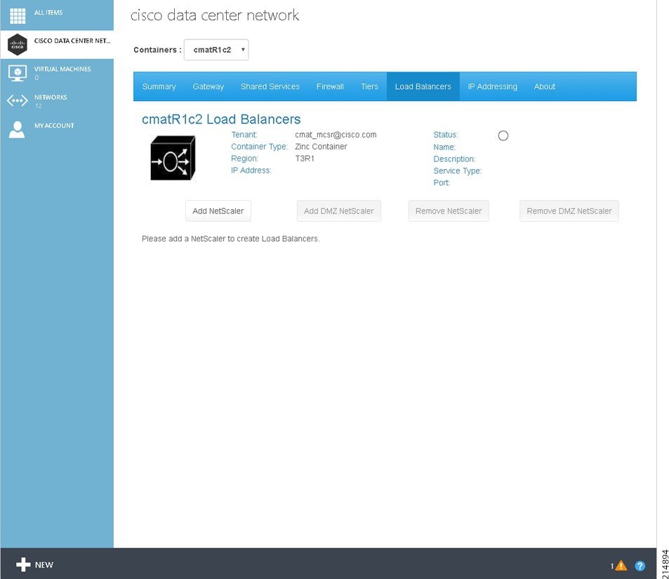
Adding a Citrix NetScaler VPX
To add a load balancer for the first time, you must first add a Citrix NetScaler1000V:
Step 1![]() On the Load Balancers Tab screen, you see the message: “Please add a NetScaler to create Load Balancers”, as shown in the following screen.
On the Load Balancers Tab screen, you see the message: “Please add a NetScaler to create Load Balancers”, as shown in the following screen.
Figure 2-56 Create a Citrix NetScaler VPX
You see the message “NetScaler create request has been created. Please wait 5-10 minutes for the NetScaler to come up. You will need to refresh the page or return to the tab.”, as shown in the following screen.
Figure 2-57 Citrix NetScaler VPX Being Created
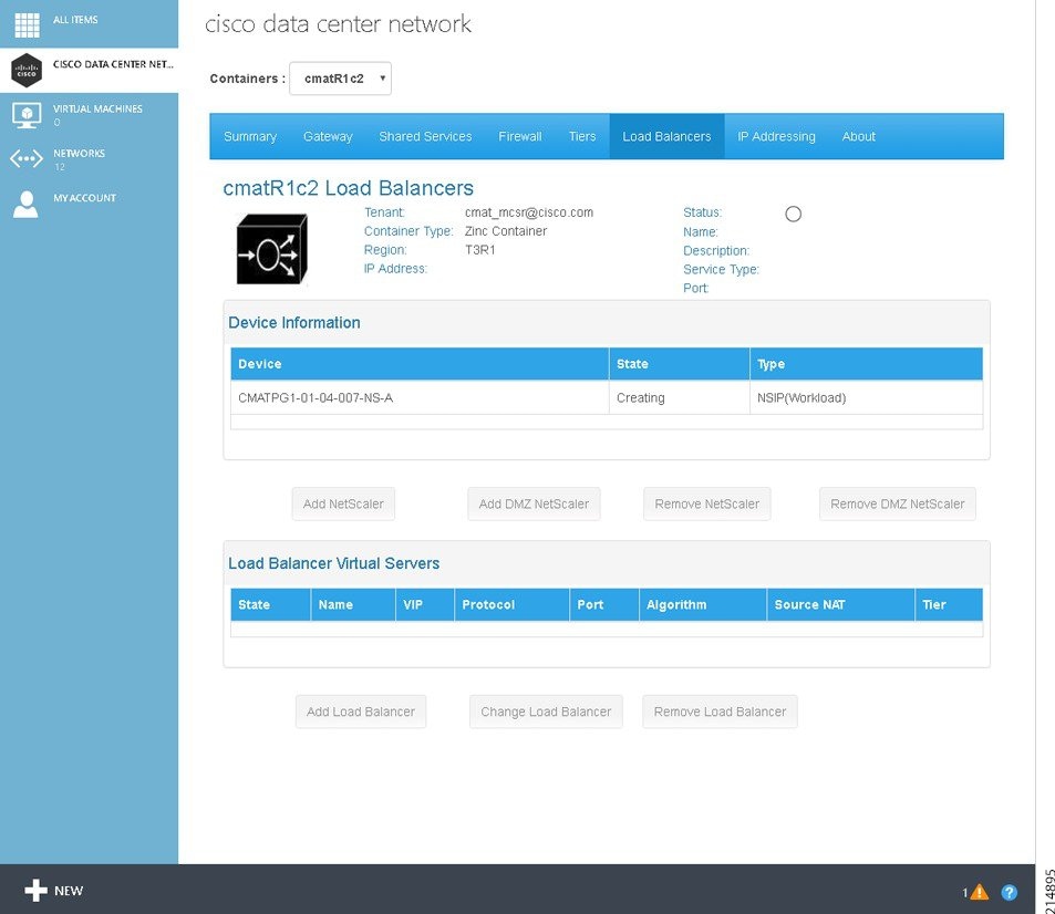
Cisco CNAP checks the configuration of your subscription to determine if it includes a SLB (Citrix NetScaler VPX). If it does, Cisco CNAP configures and onboards the Citrix NetScaler VPX.
Step 3![]() When the Citrix NetScaler VPX is configured, refresh the screen or click the Load Balancers tab again. You see the configured device with a State of LicenseNeeded and the message “Please contact your Cloud Administrator to license your NetScalers”, as shown in the following screen.
When the Citrix NetScaler VPX is configured, refresh the screen or click the Load Balancers tab again. You see the configured device with a State of LicenseNeeded and the message “Please contact your Cloud Administrator to license your NetScalers”, as shown in the following screen.
Figure 2-58 Citrix NetScaler VPX License Needed
Contact your cloud provider to license the Citrix NetScaler VPX(s).
Step 4![]() Once the Cloud Administrator licenses the Citrix NetScaler VPX, on the Tenant Portal Load Balancers tab, the Citrix NetScaler VPX will now be in an Active state, as shown in the following screen.
Once the Cloud Administrator licenses the Citrix NetScaler VPX, on the Tenant Portal Load Balancers tab, the Citrix NetScaler VPX will now be in an Active state, as shown in the following screen.
Figure 2-59 Citrix NetScaler VPX Active after Licensing
Adding a Load Balancer
After you have added a Citrix NetScaler VPX and confirmed that your cloud provider has licensed the Citrix NetScaler VPX (on the Load Balancers tab the Citrix NetScaler VPX is in an Active state), you can add a Virtual Server:
Step 1![]() On the Load Balancers Tab screen, click Add Load Balancer.
On the Load Balancers Tab screen, click Add Load Balancer.
Figure 2-60 Add Load Balancer Screen
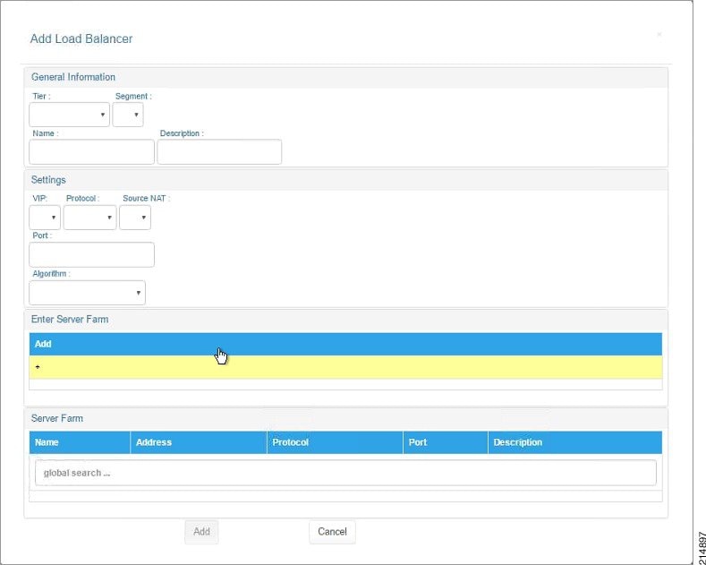
Enter the following information:
–![]() Segment:—Select the segment.
Segment:—Select the segment.
–![]() Description:—Enter a description.
Description:—Enter a description.
–![]() Protocol:—Select a protocol: HTTP or SSL
Protocol:—Select a protocol: HTTP or SSL
–![]() Port:—Enter the port number.
Port:—Enter the port number.
–![]() Source NAT:—Select the source NAT.
Source NAT:—Select the source NAT.
–![]() Algorithm:—Select the algorithm: LEASTCONNECTION or ROUNDROBIN.
Algorithm:—Select the algorithm: LEASTCONNECTION or ROUNDROBIN.
You can add a server. For more information, see the next section.
Step 2![]() When you are finished, click Add.
When you are finished, click Add.
Adding a Load Balancer Server
Step 1![]() On the Add Load Balancer screen shown in the previous section, under Enter Server Farm, click +.
On the Add Load Balancer screen shown in the previous section, under Enter Server Farm, click +.
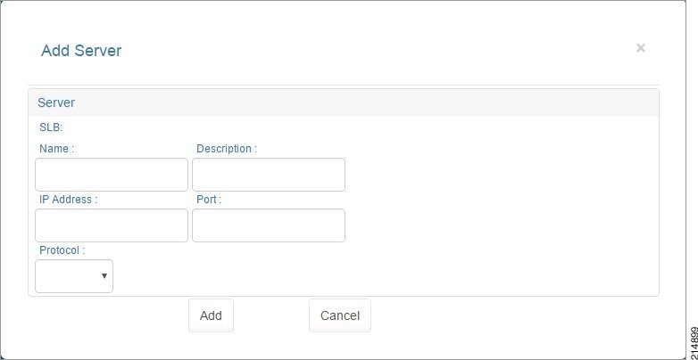
Enter the following information:
- Name:—Enter a name for the server.
- Description:—Enter a description for the server.
- IP Address:—Enter the IP address of the server.
- Protocol:—Select the protocol: HTTP or SSL
- Port:—Enter the port number.
Step 2![]() When you are finished, click Add.
When you are finished, click Add.
You return to the previous screen.
Changing a Load Balancer
Step 1![]() On the Load Balancers Tab screen, under Load Balancer Virtual Servers, click the load balancer you want to change, then click Change Load Balancer.
On the Load Balancers Tab screen, under Load Balancer Virtual Servers, click the load balancer you want to change, then click Change Load Balancer.
You see the Update Load Balancer screen.
Figure 2-62 Update Load Balancer
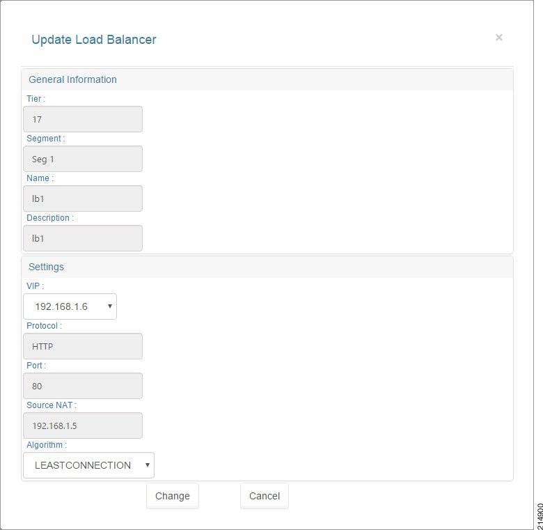
The screen displays the following fields, however you can only change the VIP and the Algorithm:
–![]() Tier:—The tier associated with the SLB.
Tier:—The tier associated with the SLB.
–![]() Segment:—The segment associated with the SLB.
Segment:—The segment associated with the SLB.
–![]() Description:—A description of the SLB.
Description:—A description of the SLB.
–![]() VIP:—You can change the VIP.
VIP:—You can change the VIP.
–![]() Protocol:—The protocol associated with the SLB: HTTP or SSL
Protocol:—The protocol associated with the SLB: HTTP or SSL
–![]() Port:—The port number associated with the SLB.
Port:—The port number associated with the SLB.
–![]() Source NAT:—The source NAT associated with the SLB.
Source NAT:—The source NAT associated with the SLB.
–![]() Algorithm:—You can change the algorithm: LEASTCONNECTION or ROUNDROBIN.
Algorithm:—You can change the algorithm: LEASTCONNECTION or ROUNDROBIN.
Step 2![]() When you are finished, click Change.
When you are finished, click Change.
Changing a Server Farm Server
To change the IP address of a load balancer server:
Step 1![]() On the Load Balancers Tab screen, click the Load Balancer Virtual Server you want to change, then under Server Farm click the server you want to change, then click Change Server.
On the Load Balancers Tab screen, click the Load Balancer Virtual Server you want to change, then under Server Farm click the server you want to change, then click Change Server.
You see the Update Server screen.
Figure 2-63 Update Server Load Balancer Server
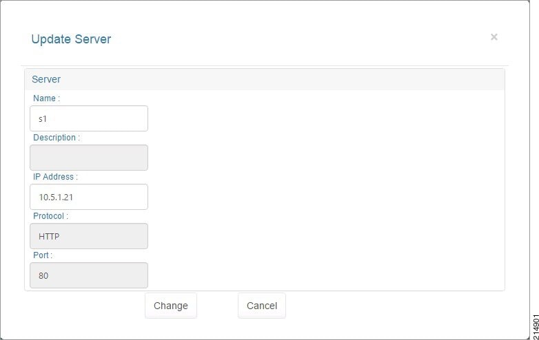
The screen displays the following:
- Name:—Name of the server.
- Description:—Displays a description.
- IP Address:—You can change this field.
- Protocol:—HTTP or SSL.
- Port:—The port number.
Step 2![]() When you are finished, click Change.
When you are finished, click Change.
Removing a Load Balancer
To remove a load balancer, on the Load Balancers Tab screen, click the Load Balancer Virtual Server you want to remove, then click Remove.
Removing a Server Farm Server
To remove a server, on the Load Balancers Tab screen, click the Load Balancer Virtual Server you want with the server you want to remove, then under Server Farm click the server you want to remove, then click Remove.
Removing a Citrix NetScaler VPX
Step 1![]() To remove a Citrix NetScaler VPX, which also removes the current load balancers, on the Load Balancers Tab screen, click the Citrix NetScaler VPX you want to remove, then click Remove.
To remove a Citrix NetScaler VPX, which also removes the current load balancers, on the Load Balancers Tab screen, click the Citrix NetScaler VPX you want to remove, then click Remove.
 Feedback