Extending Cisco SD-WAN into AWS with Cisco Cloud onRamp for IaaS and TGW Interconnection
Available Languages
Bias-Free Language
The documentation set for this product strives to use bias-free language. For the purposes of this documentation set, bias-free is defined as language that does not imply discrimination based on age, disability, gender, racial identity, ethnic identity, sexual orientation, socioeconomic status, and intersectionality. Exceptions may be present in the documentation due to language that is hardcoded in the user interfaces of the product software, language used based on RFP documentation, or language that is used by a referenced third-party product. Learn more about how Cisco is using Inclusive Language.
- US/Canada 800-553-2447
- Worldwide Support Phone Numbers
- All Tools
 Feedback
 Feedback
Define – Cisco Cloud onRamp for IaaS introduction
Design - Cisco Cloud onRamp for IaaS use case and feature overview
Deploy - Cisco Cloud onRamp for IaaS with AWS
Process: Deploy a transit VPC with Cisco Cloud onRamp for IaaS
Process: Discover and map host VPCs to the transit VPC
Operate - Cisco Cloud onRamp for IaaS monitoring
Process: Monitor Cisco Cloud onRamp for IaaS
Interconnecting Cisco SD-WAN with AWS Transit Gateway (TGW)
Process: Manually connecting Cisco CSR 1000v routers within a transit VPC to an AWS TGW
Appendix A: Changes from previous versions
Appendix B: Hardware and software used for validation
Appendix C: Cisco SD-WAN Edge router configuration template summary
Appendix D: Transit VPC Cisco SD-WAN Edge router CLI configuration
Appendix E: Verify AWS prerequisites
Appendix F: Creating an AWS IAM Role
Appendix G: Generating an AWS SSH key pair
About the guide
This guide is intended to provide technical guidance to design, deploy, and operate Cisco Cloud onRamp for IaaS. The following IaaS public cloud providers are supported with Cisco Cloud onRamp for IaaS as of Cisco vManage release 20.1.1, which this guide is based upon:
● Amazon Web Services (AWS)
● Microsoft Azure
This deployment guide discusses AWS only.
The deployment models discussed include both Cisco IOS XE SD-WAN and Cisco vEdge devices, collectively referred to as Cisco SD-WAN Edge routers. The last section of this guide describes interconnection of the Cisco SD-WAN with one or more AWS VPCs using an existing AWS Transit Gateway (TGW) and an AWS transit VPC containing Cisco CSR 1000v routers, separate from the functionality within Cisco Cloud onRamp for IaaS.
Although this deployment guide is about Cisco Cloud onRamp for IaaS, it is presumed that:
● Cisco SD-WAN controllers (vManage, vBond, and vSmart) are already deployed with valid certificates.
● Cisco SD-WAN Edge devices and vSmart controllers have configurations – feature templates defined, device templates associated, and are in vManage mode.
● Cisco SD-WAN Edge devices at branch and campus locations have been onboarded, have established control connections to the Cisco SD-WAN controllers, and have established data tunnels to other SD-WAN Edge devices across all available transports.
For more information on SD-WAN controller design and deployment, please refer to the Cisco SD-WAN Design Guide and the Cisco SD-WAN End-to-End Deployment Guide at the following URLs:
https://www.cisco.com/c/en/us/td/docs/solutions/CVD/SDWAN/cisco-sdwan-design-guide.html
https://www.cisco.com/c/dam/en/us/td/docs/solutions/CVD/SDWAN/SD-WAN-End-to-End-Deployment-Guide.pdf
This document contains four major sections:
● The Define section discusses various IaaS public cloud connectivity models and introduces Cisco Cloud onRamp for IaaS.
● The Design section describes the AWS transit VPC design used by Cisco Cloud onRamp for IaaS.
● The Deploy section is divided into two parts. The first part provides information regarding the prerequisites necessary for deploying Cisco Cloud onRamp for IaaS using AWS as the IaaS public cloud provider. The second part discusses the automated deployment workflow of Cisco Cloud onRamp for IaaS.
● The Operate section shows some of the monitoring capabilities of Cisco Cloud onRamp for IaaS available through the Cisco vManage web-based graphical user interface (GUI).
An additional section just before the Appendices discusses how to manually connect an AWS Transit Gateway into an existing transit VPC consisting of Cisco CSR 1000v routers. This section is only for customers who may have existing AWS Transit Gateways, or Cisco vManage releases below 20.3. In Cisco vManage release 20.3, Cisco Cloud onRamp for Multi-Cloud is introduced. Cisco Cloud onRamp for Multi-Cloud automates the creation of a transit VPC along with an AWS TGW, which together are referred to as a Cloud Gateway.
Audience
The audience for this document includes network design engineers, network operations personnel, and security operations personnel who wish to implement Cisco SD-WAN secure virtual private network (VPN) connectivity from their private networks to one or more Amazon Web Services (AWS) virtual private clouds (VPCs).
Define – Cisco Cloud onRamp for IaaS introduction
About the solution
In a multi-cloud world, IT managers are quickly realizing the benefits of cloud computing services such as infrastructure as a service (IaaS). IaaS public cloud providers, such as AWS, allow organizations to prototype new applications more rapidly and cost-effectively. Instead of procuring, installing, and managing hardware – which could take months to accomplish – you can easily use the on-demand and scalable compute services in AWS. This allows you to focus your resources on applications rather than on managing the data center and physical infrastructure.
With the use of IaaS, expenses shift from fixed costs for hardware, software, and data center infrastructure to variable costs based on the usage of compute resources and the amount of data transferred between the private data center, campus, and branch locations, and the IaaS public cloud provider. Therefore, you must also be able to monitor the usage of such resources for cost tracking and/or internal billing purposes.
This guide focuses on how to deploy secure network connectivity from private network campus and branch locations to one or more Amazon Web Services (AWS) virtual private clouds (VPCs) using the Cisco SD-WAN Cloud onRamp for Infrastructure as a Service (IaaS) feature within Cisco vManage version 20.1.1. A VPC is an on-demand virtual network, logically isolated from other virtual networks within an IaaS public cloud.
With this design, host VPCs (also referred to as spoke VPCs within this document) connect via AWS Site-to-Site VPN Connections to a transit VPC consisting of one or more redundant pairs of Cisco vEdge Cloud or Cisco CSR 1000v virtual form-factor routers. The transit VPC is in turn part of the SD-WAN Secure Extensible Network (SEN), which provides direct SD-WAN VPN connectivity to branch and campus sites within the private network. The deployment of the AWS transit VPC, Cisco vEdge Cloud or CSR 1000v routers within the transit VPC, AWS Site-to-Site VPN Connections from the host VPCs to the transit VPC, and SD-WAN VPN connectivity from the transit VPC to branch and campus sites within the private network is fully automated through the Cisco SD-WAN Cloud onRamp for IaaS feature. This design is generally targeted for customers with a smaller number of host VPCs that are required to be connected into the Cisco SD-WAN.
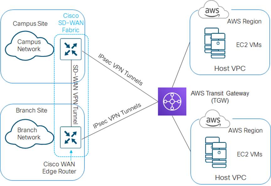
Another design option, generally targeted for customers with a larger number of host VPCs that are required to be connected into the Cisco SD-WAN, is to connect AWS host VPCs to an AWS Transit Gateway (TGW), which is then connected to a transit VPC. This functionality is provided through the Cisco Cloud onRamp for Multi-Cloud feature within Cisco vManage release 20.3 for new deployments – meaning Cisco Cloud onRamp for Multi-Cloud will create a new AWS Transit Gateway. In Cisco vManage release 20.3 Cisco Cloud onRamp for Multi-Cloud will not attach an existing AWS Transit Gateway (with or without attached AWS host VPCs) to a transit VPC. Cisco Cloud onRamp for Multi-Cloud supports only Cisco CSR 1000v routers within the transit VPC.
The Cisco Cloud onRamp for Multi-Cloud design is not the focus of this deployment guide. However, the last section of this guide (before the Appendices) will discuss how to manually connect a transit VPC to an AWS Transit Gateway, using AWS site-to-site VPN connections and BGP routing. This functionality is discussed separately from Cisco Cloud onRamp for IaaS and is targeted for customers with existing AWS Transit Gateways, Cisco SD-WAN deployments which have not yet migrated to leverage the Cisco Cloud onRamp for Multi-Cloud feature introduced in Cisco vManage version 20.3, or those who wish to connect a transit VPC consisting of Cisco vEdge Cloud routers to an AWS Transit Gateway.
Design options
There are multiple options for connecting AWS host VPCs to the Cisco SD-WAN. The following sections present these design options and discuss some of the advantages and disadvantages of each option.
Design option #1 – Cisco Cloud onRamp for IaaS transit VPC design
The first design option is to extend the Cisco SD-WAN fabric out to AWS through a transit VPC. A transit VPC is a VPC that has the single purpose of transporting traffic between other VPCs as well as campus and branch locations. AWS host VPCs are then connected to the transit VPC through AWS Site-to-Site VPN connections.
This is the design option implemented by Cisco Cloud onRamp for IaaS for connecting AWS host VPCs to the Cisco SD-WAN network. This option is fully automated and managed through the Cisco vManage web-based graphical user interface (GUI). An example is shown in the following figure.
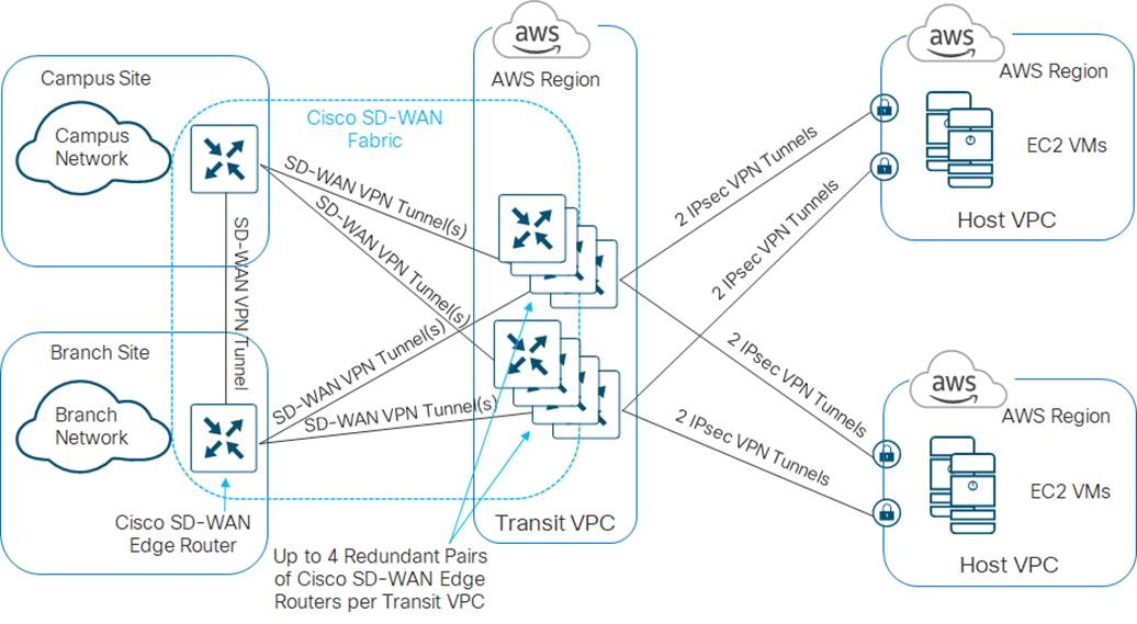
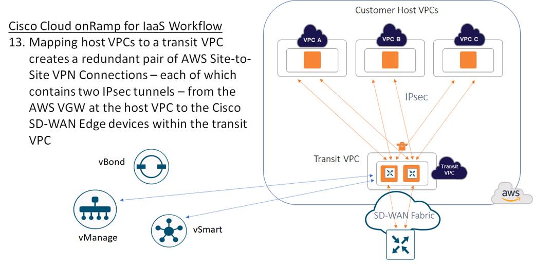
The Cisco Cloud onRamp for IaaS feature within the Cisco SD-WAN solution first provisions a transit VPC with one or more redundant pairs of Cisco SD-WAN Edge (Cisco vEdge Cloud or Cisco CSR 1000v) routers. AWS Site-to-Site VPN Connections are then established between AWS Virtual Private Gateways (VGWs) at the host VPCs and the Cisco SD-WAN Edge routers within the transit VPC. Since each AWS Site-to-Site VPN Connection consists of a pair of redundant IPsec tunnels, a total of four IPsec tunnels is established from each AWS host VPC to the transit VPC.
Traffic between AWS host VPCs flows through the dedicated transit VPC. Traffic from campus and branch sites to the host VPCs also passes through the transit VPC via the Cisco SD-WAN fabric (VPN connections established between Cisco SD-WAN Edge routers within the campus and branch sites and each of the Cisco SD-WAN Edge routers within the transit VPC).
| Tech tip |
| Traffic between campus and branch sites flows directly to each other over the Cisco SD-WAN fabric (SD-WAN VPN connections established between Cisco SD-WAN Edge routers within the campus and branch sites). |
Advantages and disadvantages of the Cisco Cloud onRamp for IaaS transit VPC design
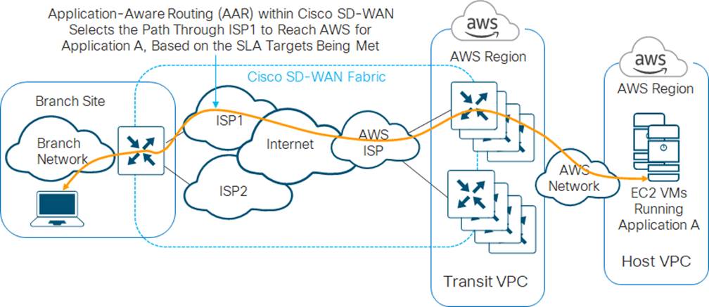
One of the primary benefits of the Cisco Cloud onRamp for IaaS transit VPC design is that it extends the Cisco SD-WAN fabric into the IaaS public cloud provider. This allows campus and branch locations which are part of the Cisco SD-WAN fabric to leverage features such as Application Aware Routing (AAR) to choose the best transport network to reach the IaaS public cloud provider. This benefit applies to internal applications which may be hosted in private (non-publicly accessible) VPCs within an IaaS public cloud provider such as AWS, instead of being hosted in a traditional on-premises data center. An example is shown in the following figure.
One of the downsides of the Cisco Cloud onRamp for IaaS transit VPC design is that each host VPC has to establish an AWS Site-to-Site VPN Connection to each router of a redundant pair of Cisco SD-WAN Edge devices within the transit VPC. Since each AWS Site-to-Site VPN Connection consists of two IPsec tunnels, and since there are two routers in each redundant pair of Cisco SD-WAN Edge devices within the transit VPC – each host VPC adds four additional IPsec tunnels across the pair of Cisco SD-WAN Edge devices within the transit VPC. As the number of AWS host VPCs increases, so does the number of IPsec tunnels that must be supported on the Cisco SD-WAN Edge devices within the transit VPC. This somewhat limits the scalability of the design.
However, this is somewhat offset by the ability to support up to four pairs of Cisco SD-WAN Edge devices within a transit VPC, and the ability to create multiple transit VPCs as needed. Each pair of Cisco SD-WAN Edge devices can support up to 32 host VPCs – although the actual number of host VPCs you should map to a single Cisco SD-WAN Edge device pair within a transit VPC will also depend upon your overall throughput requirements, as well as the size (performance) of the AWS EC2 instances which host the Cisco SD-WAN Edge devices.
| Tech tip |
| Individual IPsec tunnels within AWS Site-to-Site VPN Connections support up to 1.25 Gbps of throughput. Note, however, that multiple AWS Site-to-Site VPN Connections utilizing the same Virtual Private Gateway (VGW) are bound by an aggregate throughput limit from AWS of up to 1.25 Gbps, as discussed in the following AWS document. |
Design option #2 – Cisco Cloud onRamp for Multi-Cloud SD-WAN Cloud Gateway design
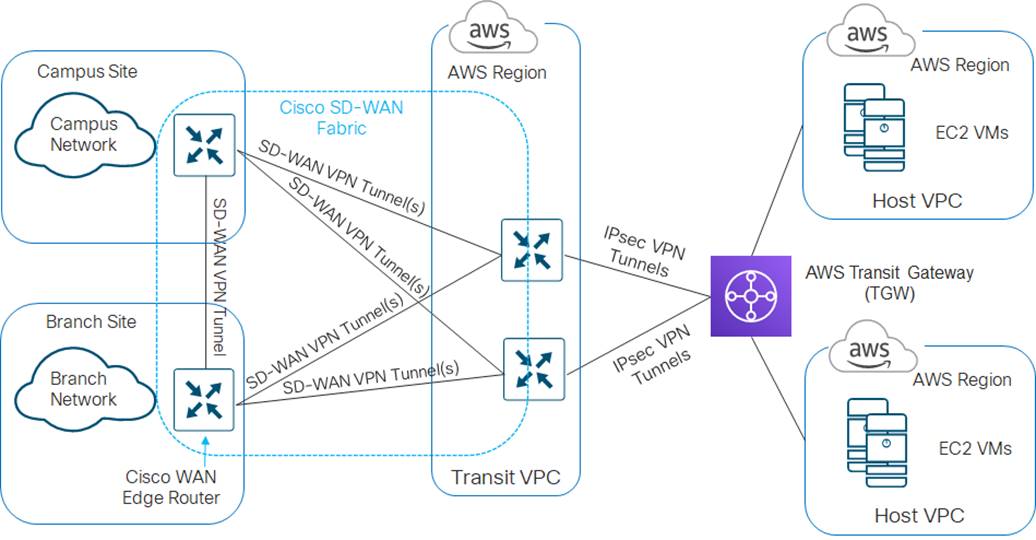
The second design option again extends the Cisco SD-WAN fabric to AWS through a transit VPC. However, AWS host VPCs are not directly connected to the transit VPC. Instead host VPCs are connected to an AWS Transit Gateway (TGW) through VPC attachments.
| Tech tip |
| AWS Transit Gateways support three types of attachments – VPC, VPN, and Peering Connection. With VPC attachments, one or more subnets within the VPC are directly attached to the AWS Transit Gateway. Multiple subnets (each within a different AWS availability zone) within the VPC provide a level of resiliency in attaching a host VPC to the AWS Transit Gateway. With VPN attachments, one or more AWS Site-to-Site VPN Connections (each of which supports two IPsec tunnels) are used to attach to the AWS Transit Gateway. Peering Connections are used to connect AWS Transit Gateways to other AWS Transit Gateways in different regions and/or across different AWS accounts. |
The AWS Transit Gateway is connected to the transit VPC through VPN attachments. The combination of the transit VPC connected to the AWS Transit Gateway is referred to as the SD-WAN Cloud Gateway (CGW).
This is the design option implemented for Cisco CSR 1000v routers by Cisco Cloud onRamp for Multi-Cloud, with the SD-WAN Cloud Gateway selection, for connecting AWS host VPCs to the Cisco SD-WAN network. This option is automated and managed through the vManage web-based graphical user interface (GUI) as of Cisco vManage release 20.3 / Cisco IOS XE release 17.3 for new deployments – meaning Cisco Cloud onRamp for Multi-Cloud will create a new AWS Transit Gateway. In Cisco vManage release 20.3, Cisco Cloud onRamp for Multi-Cloud will not attach an existing AWS Transit Gateway (with or without attached host VPCs) to a transit VPC.
An example of the Cisco Cloud onRamp for Multi-Cloud Cloud Gateway design is shown in the following figure.
When you select the SD-WAN Cloud Gateway option within Cisco Cloud onRamp for Multi-Cloud in the Cisco SD-WAN solution, Cisco vManage does the following:
● Provisions an AWS Transit Gateway within the AWS region selected
● Provisions a transit VPC with a redundant pair of Cisco CSR 1000v routers, also within the AWS region selected
You can then map tagged host VPCs to SD-WAN service VPNs to allow traffic flows, as well as map tagged host VPCs to other tagged host VPCs to allow for traffic flows between host VPCs. Tags are used to abstract VPC names into logical entities for ease of mapping. When you map the first host VPC to the Cloud Gateway, Cisco Cloud onRamp for Multi-Cloud will connect the transit VPC to the AWS Transit Gateway via a VPN attachment (AWS Site-to-Site VPN Connection).
With the Cisco Cloud onRamp for Multi-Cloud SD-WAN Cloud Gateway design, traffic between host VPCs flows through the AWS Transit Gateway. Traffic from campus and branch sites to the host VPCs passes first through the transit VPC via the Cisco SD-WAN fabric (VPN connections established between Cisco SD-WAN Edge routers within the campus and branch sites and each of the Cisco CSR 1000v routers within the transit VPC). Traffic then passes through the AWS Transit Gateway, to reach the host VPCs.
| Tech tip |
| Traffic between campus and branch sites flows directly to each other over the Cisco SD-WAN fabric (SD-WAN VPN connections established between Cisco SD-WAN Edge routers within the campus and branch sites). |
Advantages and disadvantages of the Cisco Cloud onRamp for Multi-Cloud Cloud Gateway design
One of the primary benefits of the Cisco Cloud onRamp for Multi-Cloud SD-WAN Cloud Gateway design is that it again extends the Cisco SD-WAN fabric into the IaaS public cloud provider, as show in Figure 3 earlier. This allows campus and branch locations which are part of the Cisco SD-WAN fabric to leverage features such as Application Aware Routing (AAR) to choose the best transport network to reach the IaaS public cloud provider. This benefit applies to internal applications which may be hosted in private (non-publicly accessible) VPCs within an IaaS public cloud provider such as AWS, instead of being hosted in a traditional on-premises data center.
Since each host VPC is connected to the AWS Transit Gateway via a VPC attachment instead of a VPN attachment, the design is more scalable than the Cisco Cloud onRamp for IaaS transit VPC design.
| Tech tip |
| AWS Transit Gateways support up to 50 Gbps of throughput per VPC. For additional information regarding performance and limits of AWS Transit Gateways, please refer to the AWS document at the following URL. |
Only the connection between the transit VPC and the AWS Transit Gateway uses VPN attachments (Site-to-Site VPN Connections). However, multiple VPN attachments may be provisioned between the redundant pair of Cisco CSR 1000v routers deployed within the transit VPC, and the AWS Transit Gateway, based on the SD-WAN service VPNs which are extended to the host VPCs. AWS also supports Transit Gateway-to-Transit Gateway peering, further increasing the scalability of the overall design.
One downside of the Cisco Cloud onRamp for Multi-Cloud Cloud Gateway design is that the automation of the SD-WAN Cloud Gateway (the combination of the AWS TGW connected to the transit VPC) is only supported from Cisco vManage release 20.3 / IOS XE release 17.3 and higher, and only for Cisco CSR 1000v routers within the transit VPC. Also, the initial release only supports the creation of an AWS Transit Gateway (i.e. a new AWS Transit Gateway deployment), not the use of an existing AWS Transit Gateway with host VPCs already connected to it. It is for this reason that the last section of this document shows how to manually connect a transit VPC to an existing AWS Transit Gateway.
Design option #3 – Cisco Cloud onRamp for Multi-Cloud Branch Connect design
A third option is to connect host VPCs to an AWS Transit Gateway; and then also connect Cisco SD-WAN Edge devices at campus and branch locations directly to the AWS Transit Gateway.
Advantages and disadvantages of the Cisco Cloud onRamp for Multi-Cloud Branch Connect design
This option does not extend the Cisco SD-WAN fabric directly to the IaaS public cloud provider. Therefore, the benefits of using Application Aware Routing (AAR) to choose the best transport network to reach the IaaS public cloud provider cannot be realized.
However, since this design does not involve a transit VPC, no incremental expenses are incurred running AWS EC2 instances which support Cisco SD-WAN Edge routers within the transit VPC. However, recurring incremental charges for each Site-to-Site VPN Connection (from the Cisco SD-WAN Edge routers within campus and branch locations to the AWS Transit Gateway) as well as transport charges across those IPsec VPN tunnels still apply.
Since each AWS host VPC connects to the AWS Transit Gateway through a VPC connection, host VPC to host VPC throughput is more scalable than using AWS Virtual Private Gateways (VGWs) and Site-to-Site VPN connections. Also, since each Cisco SD-WAN campus or branch location establishes one or more AWS Site-to-Site VPN Connections (which consist of two IPsec tunnels) depending upon how many service VPNs are extended to the AWS Transit Gateway, the overall bandwidth from all Cisco SD-WAN sites to the AWS Transit Gateway may be higher.
The configuration of the AWS Site-to-Site VPN connections at the AWS Transit Gateway requires the static configuration of the public IP address of each branch Cisco SD-WAN Edge router as a Customer Gateway (CGW) definition within AWS. The AWS Customer Gateway definitions serve as the customer-side IP address endpoints for the IPsec tunnels within the AWS Site-to-Site VPN connections. Because of this, it is preferred that the public IP address issued by the Internet Service Provider (ISP) is statically configured on Cisco SD-WAN Edge router, or at least that the same public IP address is always issued to the Cisco SD-WAN Edge router, if using DHCP.
Design options covered within the use cases of this deployment guide
This deployment guide is primarily focused around Cisco Cloud onRamp for IaaS, using AWS. Therefore, the use cases within this deployment guide will mainly focus on how to implement Design option #1 – Cisco Cloud onRamp for IaaS transit VPC design. This includes transit VPC designs with either Cisco vEdge Cloud routers or Cisco CSR 1000v virtual routers, since both are supported through the Cloud onRamp for IaaS feature within the Cisco SD-WAN solution. Autoscaling will also be discussed as a means to scale the design.
This deployment guide does not cover the deployment of the Cisco Cloud onRamp for Multi-Cloud SD-WAN Cloud Gateway design deployed by Cisco vManage in release 20.3 / IOS XE release 17.3, or the Multi-Cloud Branch Connect design. The Cisco Cloud onRamp for Multi-Cloud feature will be covered in a separate future deployment guide.
However, the last section of this deployment guide (before the Appendices) presents a use-case for the manual (non-automated) connection of a transit VPC to an existing AWS Transit Gateway using Site-to-Site VPN attachments. This section is intended for Cisco SD-WAN deployments not yet running vManage release 20.3, and/or for deployments with existing AWS Transit Gateways that cannot leverage the benefits of the automation within the Cisco Cloud onRamp for Multi-Cloud feature, and/or for deployments that only implement Cisco vEdge router platforms, since the Cisco Cloud onRamp Multi-Cloud feature only implements Cisco CSR 1000v routers within the transit VPC. The use of the Cisco Cloud onRamp for Multi-Cloud feature to deploy a SD-WAN Cloud Gateway design is recommended for customers with new AWS Transit Gateways, deployments with Cisco vManage release 20.3 / IOS XE release 17.3, and customers who also currently use or wish to use Cisco CSR 1000v platforms.
| Tech tip |
| For clarity, you can implement a combination of Cisco vEdge router platforms within campus and branch locations, and Cisco CSR 1000v virtual router platforms within the AWS transit VPC. The Cisco SD-WAN fabric will be extended from your campus and branch locations to the AWS transit VPC, allowing interconnection to your host VPCs. Unlike the Cisco Cloud onRamp for IaaS feature which supports both Cisco vEdge Cloud and Cisco CSR 1000v routers within the AWS transit VPC, the Cisco Cloud onRamp for Multi-Cloud feature only supports Cisco CSR 1000v routers within the transit VPC, as of Cisco vManage release 20.3. Customers who wish to maintain only Cisco vEdge and vEdge Cloud router platforms within their Cisco SD-WAN networks cannot use the Cisco Cloud onRamp for Multi-Cloud feature within Cisco vManage release 20.3 to provide interconnection to their AWS host VPCs. |
Design - Cisco Cloud onRamp for IaaS use case and feature overview
This section focuses on a use case involving the Cisco Cloud onRamp for IaaS feature within the Cisco SD-WAN solution in order to deploy SD-WAN to AWS connectivity shown in Design option #1 - Cisco Cloud onRamp for IaaS transit VPC with AWS within the Define section of this guide.
Use case
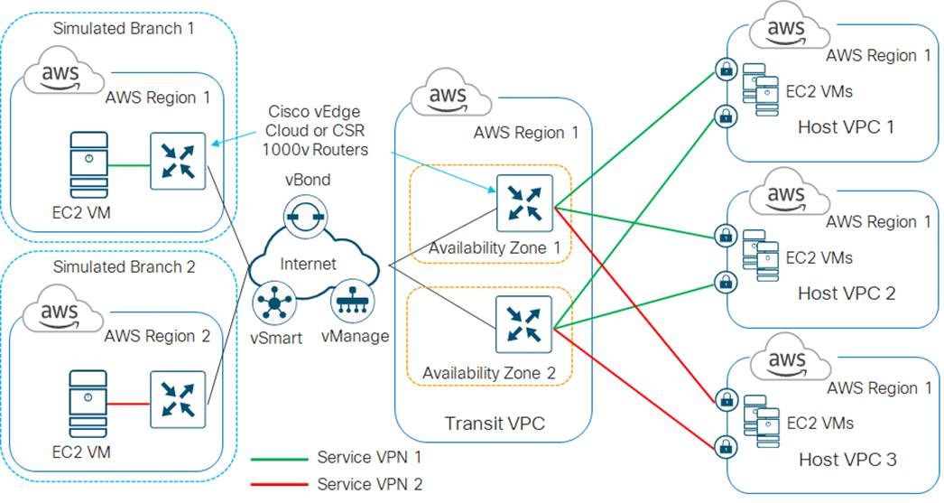
In the high-level design for this use case, a single transit VPC is created by Cisco Cloud onRamp for IaaS within an AWS region. Three existing host VPCs within the same AWS region are then mapped to the transit VPC using Cisco Cloud onRamp for IaaS. Because Cisco Cloud onRamp for IaaS is used to map the host VPCs, they connect to the Cisco SD-WAN Edge routers within the transit VPC via AWS Site-to-Site VPN Connections. This design does not make use of the Transit Gateway (TGW) functionality which AWS has added to support VPC-to-VPC communication. The host VPCs are accessed from two simulated branch locations.
This use case is deployed around the high-level design shown in the following figure.
| Tech tip |
| The branch sites were simulated using a Cisco SD-WAN Edge router (vEdge Cloud or Cisco CSR 1000v) deployed within a VPC. Both branch sites are deployed simply to test connectivity to the host VPCs which are mapped through the transit VPC. The configuration of the branch Cisco SD-WAN Edge routers, as well as the vSmart, vManage, and vBond controllers are not discussed within this deployment guide. |
Cisco SD-WAN deployments implement segmentation using different VPNs - which have a range from 0 - 65528. VPN 0 represents the transport (WAN) network for all Cisco SD-WAN deployments. Likewise, VPN 512 represents the management network for all Cisco SD-WAN deployments. These cannot be used as SD-WAN service VPNs. The remaining VPNs (1 – 511 and 513 - 65528) can be used as service VPNs. Service VPNs support the transport of customer traffic across the Cisco SD-WAN network
For this use case, two host VPCs are mapped to service VPN 1 within the transit VPC. Service VPN 1 is also configured on the LAN-side of the Cisco SD-WAN Edge router deployed within Branch 1. The third host VPC is mapped to service VPN 2 within the transit VPC. Service VPN 2 is also configured on the LAN-side of the Cisco SD-WAN Edge router deployed within Branch 2.
This configuration allows devices within Branch 1 to access applications running within AWS Elastic Compute Cloud (EC2) instances within the first two host VPCs. It also allows communication between applications running on AWS EC2 instances deployed within the first two host VPCs. Likewise, this configuration allows devices within Branch 2 to access applications running within AWS EC2 instances within the third host VPC. However, devices within Branch 1 cannot access applications running on AWS EC2 instances deployed within the third host VPC, nor can devices within Branch 2 access applications running on the AWS EC2 instances deployed within the first two host VPCs.
This design provides segmentation and therefore traffic isolation between the first two host VPCs and the third host VPC. This demonstrates the use case where different entities within an organization require access only to specific public IaaS cloud resources.
How it works
This section discusses at a high-level the Cisco Cloud onRamp for IaaS workflow when using AWS as the IaaS public cloud provider.
Prerequisites
Before configuring Cisco Cloud onRamp for IaaS, you must make sure the pre-requisites are met before configuration can be performed successfully.
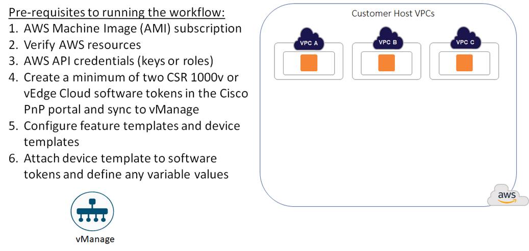
The pre-requisites include verifying you meet the AWS prerequisites, including the necessary AWS credentials and subscriptions to the Amazon Machine Image (AMI) instances for Cisco SD-WAN Edge routers (Cisco CSR 1000v virtual routers or Cisco vEdge Cloud); verifying you have available tokens/licenses for at least two additional Cisco SD-WAN Edge Routers within Cisco vManage; and configuring and deploying device templates for the Cisco SD-WAN Edge routers that will be used within the transit VPCs.
Note that the creation of the customer host VPCs, shown in the figure above, is outside the scope of this document. It is assumed that one or more customer host VPCs have already been created.
Transit VPC creation
Within the Cisco Cloud onRamp for IaaS workflow, one or more cloud instances can be created. Each cloud instance corresponds to an AWS account and region in which one or more transit VPCs can be created, and to which one or more host VPCs can then be mapped.
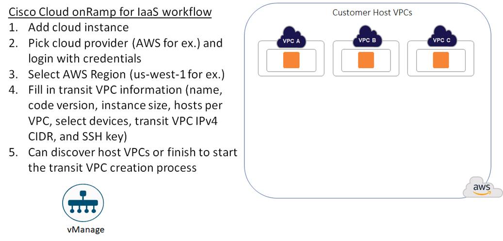
Multiple AWS accounts can be added to Cisco Cloud onRamp for IaaS, by adding either AWS Identity and Management (IAM) Roles or Access Keys. These are used by Cisco Cloud onRamp for IaaS to make the necessary Application Programming Interface (API) calls to create the transit VPC and map host VPCs to the transit VPC.
Also, within the Cisco Cloud onRamp for IaaS workflow, you specify an IPv4 CIDR block range when creating the transit VPC. The IPv4 CIDR range you configure is automatically subnetted to create the necessary subnets within the transit VPC.
Up to four pairs of redundant Cisco SD-WAN Edge routers (vEdge Cloud or Cisco CSR 1000V routers) can be provisioned and instantiated within each VPC dedicated to function as a transit point for traffic between host VPCs. The individual Cisco SD-WAN Edge routers of each redundant pair are deployed within a different availability zone within the AWS region of the transit VPC, for greater resilience in case of failure. Each Cisco SD-WAN Edge router is automatically provisioned with the following:
● A management VPN (VPN 512) - available via an AWS elastic IP address (public IP address)
● A transport VPN (VPN 0) - also available via an AWS elastic IP address (public IP address)
● One or more service VPNs (VPNs 1, 2, etc.).
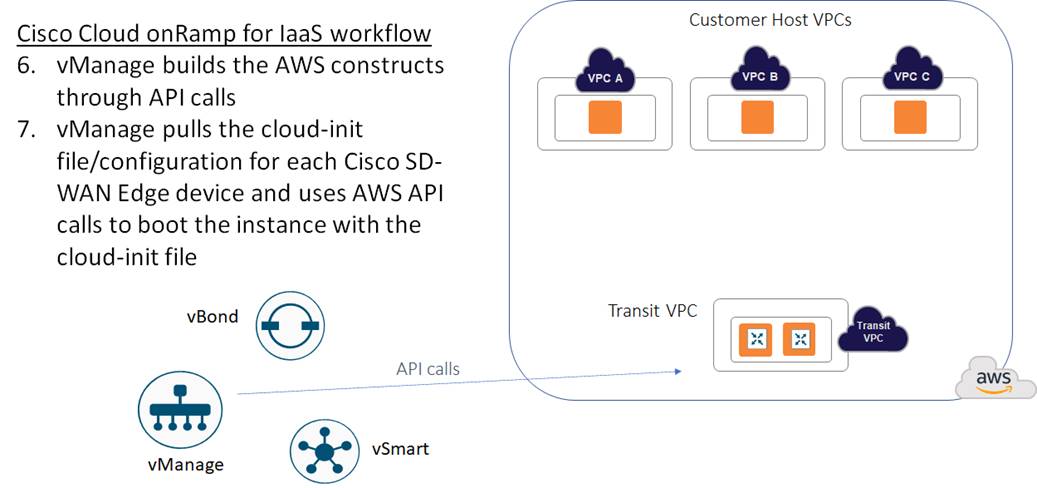
Cisco Cloud onRamp uses AWS APIs to create the AWS logical components - including the transit VPC, subnets, network interfaces, Internet gateway (IGW), and elastic IP addresses (public routable IP addresses). The contents of the cloud-init file are included within the AWS API calls used to instantiate the Cisco SD-WAN Edge device instances within the transit VPC. The cloud-init file contains both a one-time password (OTP) used to initially authenticate the specific Cisco SD-WAN Edge device to vBond and vManage, as well as the configuration of the device based on the device template and variables applied to the specific Cisco SD-WAN Edge device within vManage.
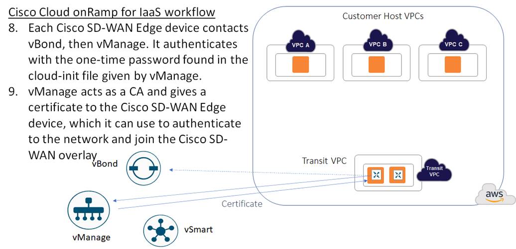
When a Cisco SD-WAN Edge device within the transit VPC device boots up, it uses the one-time password (OTP) passed within the cloud-int file to initially authenticate and connect to Cisco vBond and then Cisco vManage. Cisco vManage then acts as a certificate authority (CA), handing the Cisco SD-WAN Edge device a certificate.
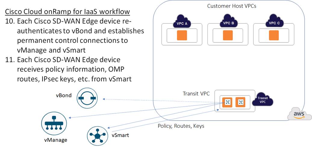
The Cisco SD-WAN Edge device then uses this certificate to re-authenticate to vBond and establish permanent control connections to vManage and vSmart. Once the control connections are established, vSmart can update the Cisco SD-WAN Edge device with policy information, OMP routing information, IPsec keys for establishing connections to other Cisco SD-WAN Edge devices, etc.
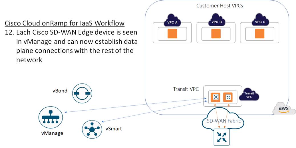
The transit VPC then provides the entry point from AWS into the Cisco SD-WAN fabric.
Host VPC to transit VPC mapping
When you map a host VPC to the transit VPC (either during the creation of the transit VPC, or separately after the creation of the transit VPC), Cisco Cloud onRamp for IaaS again uses AWS APIs to automatically create a redundant pair of AWS Site-to-Site VPN Connections from the AWS Virtual Private Gateway (VGW) at the host VPC. Each Cisco SD-WAN Edge router within the transit VPC functions as a Customer Gateway (CGW) from an AWS perspective. Each AWS Site-to-Site VPN Connection consists of a pair of IPsec tunnels established to the same Customer Gateway (CGW). Therefore, a total of four IPsec tunnels is established from each host VPC to the transit VPC.
Each AWS Site-to-Site VPN Connection is mapped to one of the two Cisco SD-WAN Edge routers of a redundant pair within the transit VPC, through the service VPN side of the Cisco SD-WAN Edge routers. Each host VPC can only be mapped to a single service VPN within the SD-WAN network. Multiple host VPCs can be mapped to the same SD-WAN service VPN at the transit VPC. This provides connectivity between the host VPCs. Alternatively, individual host VPCs can be mapped to separate SD-WAN service VPNs at the transit VPC - if network segmentation is required. In deployments where there are multiple pairs of Cisco SD-WAN Edge routers instantiated within a transit VPC, each host VPC is mapped to only one pair of redundant Cisco SD-WAN Edge routers.
Within the Cisco SD-WAN Edge routers, Cisco Cloud onRamp for IaaS dynamically configures the following:
● The combination of security parameters, including pre-shared keys, cryptographic suites, rekey intervals, etc., to be used during Internet Key Exchange version 1 (IKEv1) negotiation between the IPsec peers.
● The combination of security parameters, including cryptographic suites, rekey intervals, etc., to be used for the IPsec Security Associations (SAs).
● IPsec protected logical tunnel interfaces (called “ipsec” interfaces on Cisco vEdge platforms and “tunnel” interfaces on Cisco CSR 1000v platforms) between the Cisco SD-WAN Edge routers and the IPsec endpoints of the AWS Site-to-Site VPN Connections associated with the AWS Virtual Private Gateway (VGW) at the host VPC. These tunnel interfaces are associated to the service VPN (also referred to as a VRF on Cisco CSR 1000v routers) to which the host VPC has been mapped.
● A BGP routing instance using Autonomous System Number (ASN) 9988, along with the BGP neighbor definitions corresponding to the endpoints of the AWS Site-to-Site VPN Connections associated with the AWS Virtual Private Gateway (VGW) at the host VPC. Again, these BGP neighbors are associated to the service VPN (also referred to as a VRF on Cisco CSR 1000v routers) to which the host VPC has been mapped. BGP routes are redistributed into OMP. OMP routes are not redistributed into BGP as of vManage release 20.1.1. Instead the Cisco SD-WAN Edge routers are configured to advertise network 0.0.0.0/0 to their BGP neighbors.
Appendix D shows CLI examples of the configurations of a Cisco CSR 1000v router and a Cisco vEdge Cloud router instantiated within a transit VPC and when host VPCs have been mapped to the transit VPC. The configuration commands highlighted in bold text show the specific commands added to the configuration when host VPCs are mapped to service VPNs 1 & 2 within Cisco Cloud onRamp for IaaS. Alternatively, the configuration can be observed by establishing SSH sessions to the Cisco SD-WAN Edge devices within the transit VPC.
You should note that when host VPCs are mapped to the transit VPC, the device template assigned to the Cisco SD-WAN Edge routers does not get updated within vManage to show the additional configuration resulting from the IPsec connections and BGP routing to the host VPCs. Instead, the configurations of the Cisco SD-WAN Edge devices within the transit VPC are dynamically modified by Cisco Cloud onRamp for IaaS.
Because of this, you must exercise some caution if you wish to modify the configuration of the Cisco SD-WAN Edge routers within a transit VPC after you have mapped host VPCs to it. For example, if you add a BGP feature template to a service interface within the device template for the Cisco SD-WAN Edge router, you have to use BGP ASN 9988 in the feature template. This is the BGP ASN that Cisco Cloud onRamp for IaaS uses for the transit VPC when mapping host VPCs to the transit VPC. Network devices can only be part of a single BGP ASN at one time.
Likewise if you add IPsec VPN connections, you must make sure you don’t duplicate the tunnel interface numbers (Cisco CSR 1000v routers) or ipsec interface numbers (Cisco vEdge Cloud routers) automatically generated by Cisco Cloud onRamp for IaaS when it mapped the host VPCs to the transit VPC.
It is for this reason, also, that it is not recommended to use Cisco Cloud onRamp for IaaS to create a transit VPC with attached host VPCs, and then manually attach an AWS TGW to the transit VPC. Although it is possible to do this if you are very careful with the configuration – due to potential conflicts between the configuration automatically provisioned by Cisco Cloud onRamp for IaaS and your manual configuration, this is not recommended. Instead it is recommended you use the Cisco Cloud onRamp for Multi-Cloud feature to provision Cloud Gateways (CGWs) designs, as presented in the Design chapter of this deployment guide.
Autoscaling
For increased scale, the network administrator can provision up to four redundant pairs of Cisco SD-WAN Edge routers within each transit VPC. The network administrator also specifies the maximum number of host VPCs that can be mapped to a single Cisco SD-WAN Edge router pair within the transit VPC. Both are specified when the transit VPC is initially created but can be modified later through the Cisco Cloud onRamp for IaaS web-based user interface. Up to 32 host VPCs can be mapped to each redundant pair of Cisco SD-WAN Edge routers within each transit VPC. Each host VPC will be mapped to only one of the pairs of Cisco SD-WAN Edge routers in the transit VPC.
| Tech tip |
| The actual number of host VPCs which should be mapped to a single redundant pair of Cisco SD-WAN Edge routers depends upon the throughput requirements of each host VPC within your organization, and the size of the EC2 instances upon which the Cisco SD-WAN Edge routers are deployed within the transit VPC. |
When the transit VPC is initially created, if multiple pairs of Cisco SD-WAN Edge routers were specified within the Cloud onRamp for IaaS web-based user interface, only the first pair of redundant Cisco SD-WAN Edge routers will be instantiated within the transit VPC. Host VPCs will be mapped to the first pair of redundant Cisco SD-WAN Edge routers until the maximum number of host VPCs for the pair is reached. Once the maximum is reached, when the next host VPC is mapped to the transit VPC, Cisco Cloud onRamp for IaaS will automatically instantiate another pair of Cisco SD-WAN Edge routers within the transit VPC and map the new host VPC to the new pair of Cisco SD-WAN Edge routers. Subsequent host VPCs will be mapped to the new pair of Cisco SD-WAN Edge routers, until the maximum number of host VPCS for the pair is reached, and so on. This autoscaling feature provides additional scale for each transit VPC, while still optimizing AWS costs, since additional Cisco SD-WAN Edge routers are not instantiated within the transit VPC until they are needed.
| Tech tip |
| Cisco Cloud onRamp for IaaS will not automatically re-map existing host VPCs to balance the number of host VPCs across each redundant pair of Cisco SD-WAN Edge Routers within a transit VPC. Also, if the network administrator removes all host VPCs from a given Cisco SD-WAN Edge router pair within a transit VPC, Cisco Cloud onRamp for IaaS will not automatically terminate the unused Cisco SD-WAN Edge router pair. However, the network administrator can manually trigger the autoscaling feature within the Cisco Cloud onRamp for IaaS web-based user interface to terminate unused Cisco SD-WAN Edge router pairs within the transit VPC. |
Site ID configuration when multiple device pairs are implemented per transit VPC
The way you assign Site IDs to each set of Cisco SD-WAN Edge device pairs within a transit VPC may affect the way traffic is routed between host VPCs that connect to different device pairs. Each Cisco SD-WAN Edge router within a single device pair (Device Pair #1, Device Pair #2, etc.) should have the same Site ID. However, you can configure different Cisco SD-WAN Edge device pairs within the same transit VPC to have different Site IDs, or to all have the same Site ID.
When different pairs of Cisco SD-WAN Edge devices within a single transit VPC are configured with the same Site IDs (for example Device Pair #1 is configured for Site ID 115001, and Device Pair #2 is also configured for Site ID 115001), by default, they do not form SD-WAN VPN tunnels between the pairs. This does not allow for traffic between host VPCs connected to different device pairs within the same transit VPC to be routed directly from one device pair to the other device pair.
Within this deployment guide, since there is no service side network interface configured by Cisco Cloud onRamp for IaaS within the transit VPC for Cisco SD-WAN Edge devices, traffic cannot be directly routed between device pairs within the transit VPC unless the device pairs form SD-WAN IPsec VPN connections between each other. For example, by default, traffic from host VPC #1 connected to Device Pair #1 destined to host VPC #2 connected to Device Pair #2, will not route directly from Device Pair #1 to Device Pair #2 within the transit VPC – if the device pairs have the same Site IDs. The traffic may (depending upon your network configuration) end up routing through a campus or branch location – remote from the transit VPC – if the host VPCs are mapped to the same service VPN. The net result is that the latency of traffic between host VPC #1 and host VPC #2 may be significantly higher, and the bandwidth utilization at the remote site may be higher due to the host VPC to host VPC traffic.
This can be modified by one of the following two methods:
● Configure different Cisco SD-WAN Edge device pairs within a single transit VPC with different Site IDs
● Configure different Cisco SD-WAN Edge device pairs within a single transit VPC with the same Site IDs, but also allow same-site-tunnels within the Cisco SD-WAN Edge devices within the transit VPC
When different pairs of Cisco SD-WAN Edge devices within a single transit VPC are configured with different Site IDs (for example Device Pair #1 is configured for Site ID 115001, and Device Pair #2 is configured for Site ID 115002), by default, they form SD-WAN VPN tunnels between the device pairs. This allows for traffic between host VPCs connected to different device pairs within the same transit VPC to be routed directly from one device pair to the other device pair. For example, traffic from host VPC #1 connected to Device Pair #1 destined to host VPC #2 connected to Device Pair #2, will route directly from Device Pair #1 to Device Pair #2 within the transit VPC – if the device pairs have different Site IDs. However, a downside to this method is that it can potentially add complexity to policies, due to the fact that there are now multiple Site IDs within the transit VPC.
The second method is to configure all SD-WAN Edge device pairs within a transit VPC to have the same Site ID, and to allow same-site-tunnels. For Cisco vEdge Cloud routers, this is accomplished through the Allow same-site-tunnel setting within the Advanced section of the WAN Edge System feature template. You will need to change the Allow same-site-tunnel setting from the default value of Off to On and include the WAN Edge System feature template within the device template assigned to all of the Cisco vEdge Cloud routers within the transit VPC.
For Cisco CSR 1000V routers, the Allow same-site-tunnel setting does not appear within the Cisco System feature template. You will need to create a CLI feature template with the following lines:
system
allow-same-site-tunnels
You will then need to include the CLI feature template within the device template assigned to all of the Cisco CSR 1000V routers within the transit VPC.
In summary, to facilitate more efficient host VPC to host VPC communication when deploying multiple Cisco SD-WAN Edge device pairs within a single transit VPC, you may wish to either configure each Cisco SD-WAN Edge Device pair with a different Site ID, or configure each Cisco SD-WAN Edge Device pair with the same Site ID and allow same-site-tunnels within the configurations of each of the Cisco SD-WAN Edge devices within the transit VPC.
Transit VPC to host VPC routing
When a host VPC is mapped to a transit VPC, BGP peering relationships are established between the Cisco SD-WAN Edge devices within the transit VPC and the IPsec tunnel endpoints representing the AWS Site-to-Site VPN Connections that are associated with the AWS Virtual Private Gateway (VGW) within the host VPC. Each host VPC can only be mapped to one service VPN within the Cisco SD-WAN.
Since there are two AWS Site-to-Site VPN Connections (each of which consists of two IPsec tunnels) between the Cisco SD-WAN Edge devices within the transit VPC and the host VPC, there are a total of four IPsec tunnels for each mapped host VPC, as shown in the figure below.
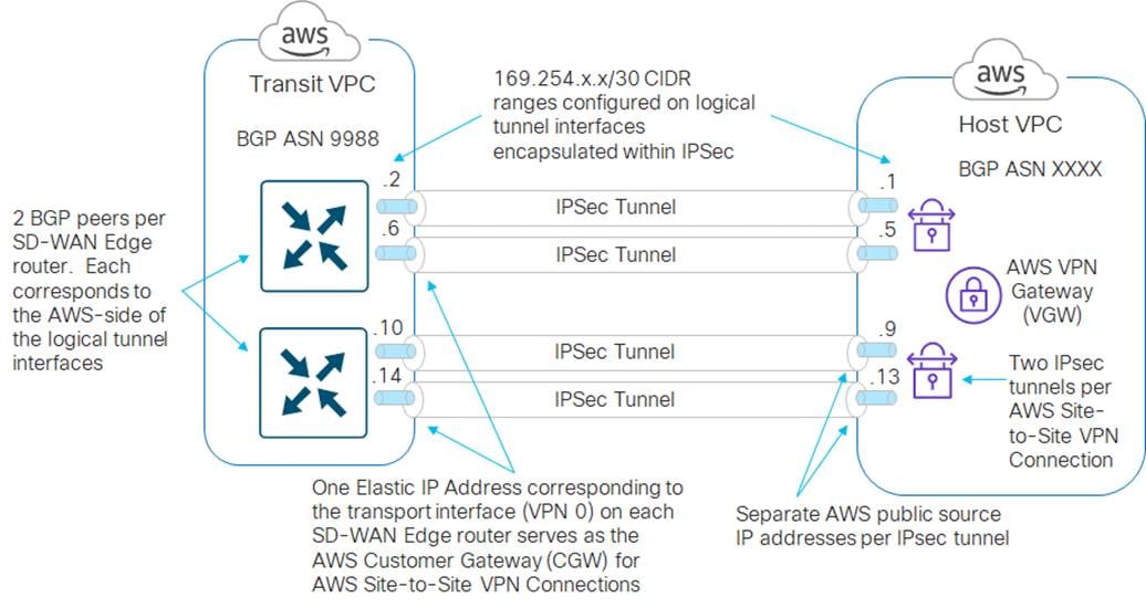
Logical tunnel interfaces are created both within the Cisco SD-WAN Edge routers and within the AWS Site-to-Site VPN Connections. The source and destination IP addresses of these logical tunnel interfaces (also referred to as inside tunnel addresses) serve as BGP peers for routing between the transit VPC and the host VPCs.
| Tech tip |
| AWS only allows tunnel interfaces in the IPv4 CIDR range of 169.254.x.x with a subnet mask of /30. A /30 subnet mask allows only two IPv4 host addresses within the subnet. AWS uses the lower IP address for the AWS-side of the tunnel. Therefore, all BGP peers to AWS which use AWS Site-to-Site VPN Connections have 169.254.x.x. IP addresses, with the lower IP address of the subnet assigned to the AWS-side of the BGP peering relationship. |
For each mapped host VPC, there are a total of four BGP peers – two BGP peers configured on one Cisco SD-WAN Edge router, and two BGP peers configured on the other Cisco SD-WAN Edge router. Hence, there are four potential paths from the transit VPC to the host VPC.
| Tech tip |
| AWS may occasionally perform updates on one of the two redundant IPsec tunnels within an AWS Site-to-Site VPN Connection. During updates, AWS may set a lower BGP outbound multi-exit discriminator (MED) value on the other IPsec tunnel. Hence, although there are four potential paths between the transit VPC and the host VPC, they may all not be equal cost paths. Please reference the AWS document at the following URL for additional details. https://docs.aws.amazon.com/vpn/latest/s2svpn/VPNRoutingTypes.html Note also, that since both AWS Site-to-Site VPN Connections (and therefore all four IPsec tunnels) utilize the same AWS Virtual Private Gateway (VGW); throughput to the host VPC is still constrained by the aggregate throughput of 1.25 Gbps of the AWS Virtual Private Gateway (VGW). Please reference the AWS document at the following URL for additional details. https://aws.amazon.com/vpn/faqs/#:~:text=Multiple%20VPN%20connections%20to%20the,Direct%20Connect%20physical%20port%20itself. |
BGP peering between the transit VPC and the host VPCs ensures that routes to the IPv4 address space within the host VPCs are visible within the service VPN at the transit VPC. These BGP routes (and optionally connected routes) must be re-distributed into OMP within the transit VPC SD-WAN Edge routers, in order to appear at remote SD-WAN sites. Redistribution of BGP routes into OMP is done either granularly within the WAN Edge VPN / Cisco VPN feature template for each service VPN, or more broadly within the vEdge OMP / Cisco OMP feature template assigned the Cisco SD-WAN Edge devices within the transit VPC.
Redistribution of OMP routes into BGP is not necessarily needed, and as of vManage release 20.1.1, Cisco Cloud onRamp for IaaS does not redistribute OMP routes into BGP. Instead Cisco Cloud onRamp for IaaS configures the Cisco SD-WAN Edge routers to advertise network 0.0.0.0/0 to the Virtual Private Gateway (VGW) within the host VPC. However, you still have a choice of enabling route propagation, when mapping a host VPC to the transit VPC. The route propagation setting within Cisco Cloud onRamp for IaaS determines whether the 0.0.0.0/0 route advertised by the Cisco SD-WAN Edge routers within the transit VPC is propagated to the main route table of the host VPC. It also determines whether routes corresponding to the IPv4 network address space within other host VPCs mapped to the same service VPN within the transit VPC are propagated to each other. This is because the Cisco SD-WAN Edge routers within the AWS transit VPC learn about these networks via BGP updates from the host VPCs, and hence no redistribution from OMP to BGP is involved.
| Tech tip |
| Every subnet within an AWS VPC must be associated with a route table. Route tables control where network traffic from the subnet is directed. If a subnet within a host VPC has not been assigned to a route table, then by default, the subnet is assigned to the main route table. You can also configure custom route tables within your VPC, and associate subnets to those custom route tables. Please reference the AWS document at the following URL for additional details regarding route tables. https://docs.aws.amazon.com/vpc/latest/userguide/VPC_Route_Tables.html |
| Tech tip |
| The route propagation setting within Cisco Cloud onRamp for IaaS uses AWS API calls to enable route propagation within the main route table of the host VPC mapped to the transit VPC. Note also, that due to the network 0.0.0.0/0 route advertised by the Cisco SD-WAN Edge routers within the transit VPC, the subnets learned via BGP from other host VPCs mapped to the same service VPN do not necessarily need to be redistributed to each other in some scenarios. The network 0.0.0.0/0 route via the AWS VGW already provides a default routing path when route propagation is enabled. Finally, there is also a limit of 100 BGP advertised routes per route table (propagated routes) within AWS. This limit cannot be increased. |
As of vManage release 20.1.1, Cisco Cloud onRamp for IaaS also configures a static default route pointing to Null0 within each Cisco SD-WAN Edge router in the transit VPC – for the service VPN to which a host VPC has been mapped. For example, if a host VPC has been mapped to service VPN 1 within a transit VPC consisting of Cisco CSR 1000V routers, then the following configuration is added to each of the CSR 1000V routers:
ip route vrf 1 0.0.0.0 0.0.0.0 Null0
Because of this default route pointing to Null0, host VPCs cannot send traffic through an AWS transit VPC configured by Cisco Cloud onRamp for IaaS, in order to reach the Internet – even if Internet connectivity is available via the Cisco SD-WAN network.
Note also that the static default route (to Null0) will be redistributed into OMP if redistribution of static routes into OMP is enables within the Cisco OMP feature template (for Cisco CSR 1000V routers) / vSmart OMP feature template (for Cisco vEdge Cloud routers), which is then included within the device template assigned to the Cisco SD-WAN Edge routers within the transit VPC.
Alternatively, redistribution of static routes into OMP can be more granularly controlled at the service VPN level. The static default route (to Null0) will be redistributed into OMP if redistribution of static routes into OMP is enabled within the Cisco VPN feature template (for Cisco CSR 1000V routers) / WAN Edge VPN feature template (for Cisco vEdge Cloud routers) for the particular service VPN, which is then included within the device template assigned to the Cisco SD-WAN Edge routers within the transit VPC.
The advertisement of a default route by the Cisco SD-WAN Edge routers within the transit VPC can be highly disruptive to your network. One method of preventing this is to disable the redistribution of static routes into OMP, either at the OMP template or VPN template for the particular service VPN, as discussed above. However, if for any reason you have additional static routes defined within the Cisco SD-WAN Edge routers, requiring the redistribution of static routes into OMP within the transit VPC, then you may need to look at filtering out the static default route through policies applied to the SD-WAN network.
The choice of whether to enable or disable route propagation, when mapping a host VPC to the transit VPC, may also be influenced based upon whether the host VPC needs outbound access to the Internet. The following sections discuss four scenarios.
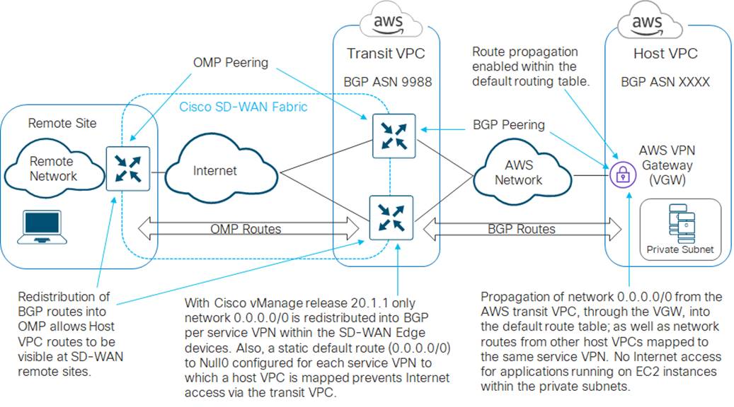
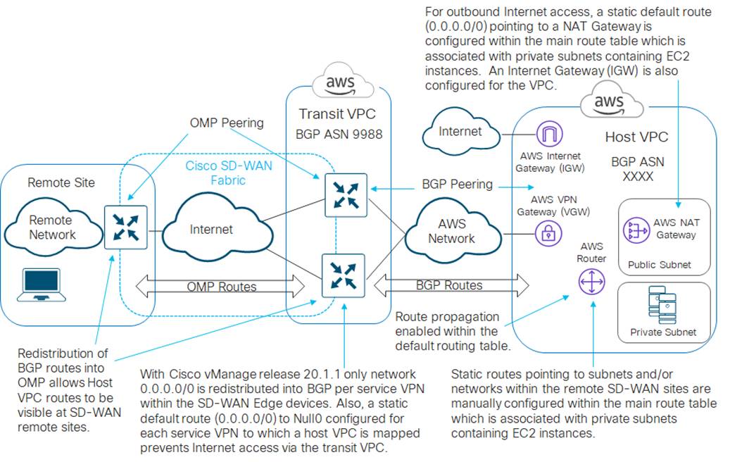
Outbound Internet access from host VPCs not required – route propagation enabled
If you choose to enable route propagation, then network 0.0.0.0/0 will be propagated from the Cisco SD-WAN Edge routers within the AWS transit VPC, through the Virtual Private Gateway (VGW) within the host VPC, to the main route table of the host VPC. Routes corresponding to the IPv4 network address space of other host VPCs mapped to the same service VPN within the AWS transit VPC will also be propagated to the main route table of the host VPC. An example is shown in the figure below.
If all of the private subnets containing AWS EC2 instances are using the main route table, then no further action is required. However, if there are private subnets containing AWS EC2 instances which have been assigned to custom (user-defined) route tables within the host VPC – you must either manually enable route propagation within the custom route tables; or manually configure a static default route (0.0.0.0/0) within the custom route tables, pointing at the AWS Virtual Private Gateway (VGW).
| Tech tip |
| From an AWS perspective, a public subnet is one where the subnet’s traffic is routed to an Internet Gateway (IGW), and a private subnet is one that does not have a route to the Internet Gateway (IGW). Please reference the AWS document at the following URL for additional details. https://docs.aws.amazon.com/vpc/latest/userguide/VPC_Subnets.html |
Since network 0.0.0.0/0 is being advertised by the Cisco SD-WAN Edge routers within the AWS transit VPC, since Internet access is generally advertised through a default route consisting of network 0.0.0.0/0, and since the Cisco SD-WAN Edge routers also have a statically configured default route pointing to Null0 for each service VPN with a host VPC mapped to it – all Internet bound traffic sent from the host VPCs will be routed to Null0 within the SD-WAN Edge routers within the transit VPC. In other words, the host VPCs will not be able to reach the Internet with this configuration.
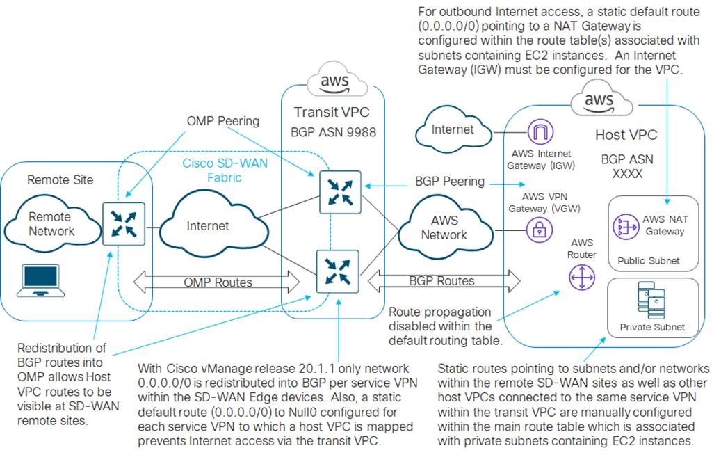
Outbound Internet access from host VPCs not required – route propagation disabled
If you choose to disable route propagation, then the network 0.0.0.0/0 route will not be propagated from the Cisco SD-WAN Edge routers within the AWS transit VPC, through the Virtual Private Gateway (VGW) within the host VPC, to the main route table of the host VPC. Routes corresponding to the IPv4 network address space of other host VPCs mapped to the same service VPN within the AWS transit VPC will also not be propagated to the main route table of the host VPC.
With this configuration choice, if your host VPCs do not require outbound Internet access, you can manually configure a static default route (0.0.0.0/0) within the route table(s) associated with each of the private subnets which contain EC2 instances within the host VPC – pointing to the AWS Virtual Private Gateway (VGW). This essentially sends all non-local traffic to the AWS Virtual Private Gateway (VGW). An example is shown in the figure below.
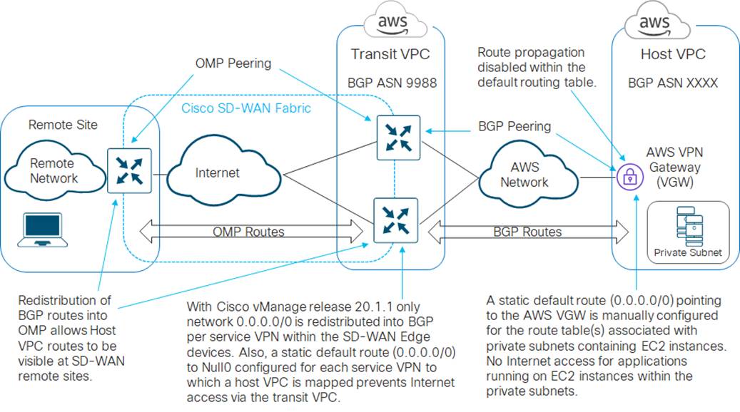
Since Internet access is generally advertised through a default route consisting of network 0.0.0.0/0, and since the Cisco SD-WAN Edge routers have a statically configured default route pointing to Null0 for each service VPN with a host VPC mapped to it – all internet bound traffic sent from the host VPCs will be routed to Null0. In other words, the host VPCs will again not be able to reach the Internet with this configuration.
Note also, that with this configuration it doesn’t really matter if you are using the main route table or custom route tables within the host VPC for your private subnets, since no routes are being propagated from the Cisco SD-WAN Edge routers within the transit VPC, through the AWS Virtual Private Gateway (VGW) and into the main route table of the VPC.
Outbound Internet access from host VPCs required – route propagation enabled
If you choose to enable route propagation, then the network 0.0.0.0/0 route will be propagated from the Cisco SD-WAN Edge routers within the AWS transit VPC, through the Virtual Private Gateway (VGW) within the host VPC, to the main route table of the host VPC. Routes corresponding to the IPv4 network address space of other host VPCs mapped to the same service VPN within the AWS transit VPC will also be propagated to the main route table of the host VPC.
With this configuration choice, if applications running on EC2 instances within private subnets in your host VPCs require outbound Internet access, you can configure the following:
● Provision two Elastic IP addresses within the host VPC
● Provision an AWS Internet Gateway (IGW) for the host VPC, and associate it to one of the Elastic IP addresses
● Provision a public subnet within the host VPC
● Provision a custom route table within the host VPC
● Provision a static default route (0.0.0.0/0) within the custom route table, pointing to the AWS Internet Gateway (IGW) for the host VPC.
● Associate the public subnet to the custom route table within the host VPC
● Provision an AWS NAT Gateway within the public subnet of the host VPC, and associate it to the other Elastic IP address
● In order to provide outbound Internet access for applications running on EC2 instances within private subnets within the host VPC, manually configure a static default route (0.0.0.0/0) within the main route table, pointing to the AWS NAT Gateway. By default, the main route table is associated with any subnet which has not be explicitly associated with a custom route table. Hence, your private subnets with EC2 instances should be associated with the main route table.
● In order to provide visibility / reachability through the AWS transit VPC to subnets and/or networks located within SD-WAN campus and branch locations, configure static routes to these subnets / networks within the main route table of the host VPC, pointing to the AWS Virtual Private Gateway (VGW) within the host VPC. Again, by default, the main route table is associated with any subnet which has not be explicitly associated with a custom route table. Hence, your private subnets with EC2 instances should be associated with the main route table.
● Visibility / reachability to networks located within other host VPCs mapped to the same service VPN within the AWS transit VPC will automatically be provided within the main route table due to the propagation of routes from the transit VPC.
This configuration selectively sends Internet-bound traffic directly from the EC2 instances within private subnets within the host VPC to the Internet via the AWS NAT Gateway (IGW) associated with the public subnet within host VPC. It sends traffic bound for either the campus and branch SD-WAN network or bound for other host VPCs mapped to the same service VPN within the transit VPC, through the AWS Virtual Private Gateway (VGW) to the transit VPC. An example is shown in the figure below.
With this design, there will actually be two routes to network 0.0.0.0/0 (default route) within the main route table of the host VPC. One route will be learned via BGP updates from the Cisco SD-WAN Edge routers within the transit VPC and propagated into the main route table of the host VPC. This route will show network 0.0.0.0/0 visible via the AWS Virtual Private Gateway (VGW) associated with the host VPC. The second route is a manually configured static route. This route will show network 0.0.0.0/0 visible via the NAT Gateway (which itself is associated to the public subnet within the host VPC).
Because static routes have a higher priority within AWS, all traffic for which there is not a more specific route within the main route table, will be sent to the AWS NAT Gateway. Hence outbound Internet traffic will be NATed to the Elastic IP address associated to the AWS NAT Gateway and sent out to the Internet. However, you will still need to configure more specific static routes within the main route table to the subnets and/or networks of the remote SD-WAN campus and branch locations, pointing to the AWS Virtual Private Gateway (VGW).
The benefit of enabling route propagation in this design is that you do not have to manually provision routes within the main route table to other host VPC networks which are mapped to the same service VPN within the transit VPC. These network routes will automatically be distributed via BGP from the SD-WAN Edge routers within the transit VPC, through the AWS Virtual Private Gateway (VGW) within the host VPC, and into the main route table of the host VPC, when route propagation is enabled. Keep in mind however, that there is a limit of at most 100 BGP routes propagated into a route table within AWS.
Also, keep in mind that enabling route propagation within Cisco Cloud onRamp for IaaS (when mapping a host VPC to the transit VPC) enables route propagation only for the main route table within the AWS host VPC. If you have associated your private subnets to custom route tables, you may need to manually enable route propagation within AWS as needed, for these custom route tables.
Outbound Internet access from host VPCs required – route propagation disabled
If you choose to disable route propagation, then the network 0.0.0.0/0 route will not be propagated from the Cisco SD-WAN Edge routers within the AWS transit VPC, through the Virtual Private Gateway (VGW) within the host VPC, to the main route table of the host VPC. Routes corresponding to the IPv4 network address space of other host VPCs mapped to the same service VPN within the AWS transit VPC will also not be propagated to the main route table of the host VPC.
With this configuration choice, if applications running on EC2 instances within private subnets in your host VPCs require outbound Internet access, you can configure the following:
● Provision two Elastic IP addresses within the host VPC
● Provision an AWS Internet Gateway (IGW) for the host VPC, and associate it to one of the Elastic IP addresses
● Provision a public subnet within the host VPC
● Provision a custom route table within the host VPC.
● Provision a static default route (0.0.0.0/0) within the custom route table, pointing to the AWS Internet Gateway (IGW) for the host VPC.
● Associate the public subnet to the custom route table within the host VPC
● Provision an AWS NAT Gateway within the public subnet of the host VPC, and associate it to the other Elastic IP address
● In order to provide outbound Internet access for applications running on EC2 instances within private subnets within the host VPC, manually configure a static default route (0.0.0.0/0) within the main route table, pointing to the AWS NAT Gateway. By default, the main route table is associated with any subnet which has not be explicitly associated with a custom route table. Hence, your private subnets with EC2 instances should be associated with the main route table.
● In order to provide visibility / reachability through the AWS transit VPC to subnets and/or networks located within SD-WAN campus and branch locations, configure static routes to these subnets / networks within the main route table of the host VPC, pointing to the AWS Virtual Private Gateway (VGW) within the host VPC.
● In order to provide visibility / reachability through the AWS transit VPC to networks located within other host VPCs mapped to the same service VPN within the AWS transit VPC, configure static routes to these networks within the main route table of the host VPC, pointing to the AWS Virtual Private Gateway (VGW) within the host VPC.
Since there is no route propagation into the main route table of the VPC, there is no benefit in associating private subnets which contain EC2 instances to the main route table with this design. However, since any subnet within a VPC not explicitly assigned to a route table is associated with the main route table, it could be considered slightly more secure to use the main route table for private subnets which contain EC2 instances and use a custom route table for the public subnet. That way, if a new subnet is configured within the host VPC, it will be treated as a private subnet. Alternatively, you could choose to associate your private subnets to custom route tables as well. In this case, the static routes to subnets and/or networks located within SD-WAN campus and branch locations, as well as within other host VPCs mapped to the same service VPN within the AWS transit VPC, would need to be defined in the appropriate custom route tables.
This configuration selectively sends Internet-bound traffic directly from the host VPC to the Internet via the AWS NAT Gateway (IGW) associated with the public subnet within host VPC; and sends traffic bound for either the campus and branch SD-WAN network or other host VPCs mapped to the same service VPN within the transit VPC, through the AWS Virtual Private Gateway (VGW) to the transit VPC. An example is shown in the figure below.
The difference between this design and the previous design is that since the networks from other host VPCs mapped to the same service VPN within the transit VPC are not propagated, you have to explicitly configure static routes to these networks within the main route table.
| Tech tip |
| Future SD-WAN releases may change the route propagation behavior, as well as the configuration of the static default route pointing to Null0 of Cisco SD-WAN Edge devices within the transit VPC. This may result in differences in the configuration choices discussed in the above sections. |
Deploy - Cisco Cloud onRamp for IaaS with AWS
Cisco Cloud onRamp for IaaS with AWS uses APIs to automate the following:
● Deployment of an AWS transit VPC with all necessary subnets, route tables, security groups, etc. This includes the instantiation of a minimum of one pair, up to a maximum of four pairs, of redundant Cisco SD-WAN Edge routers (Cisco vEdge Cloud or Cisco CSR 1000v virtual routers) within the transit VPC. Each of the Cisco SD-WAN Edge routers within a given pair is instantiated within a different AWS availability zone for resiliency.
● Discovery and mapping of host VPCs to the transit VPC via redundant AWS Site-to-Site VPN connections. The Site-to-Site VPN connections within each host VPC, as well as the Customer Gateway (CGW) gateway definitions within the host VPC, are automatically created by Cisco Cloud onRamp for IaaS. Cisco Cloud onRamp for IaaS will use an existing AWS Virtual Private Gateway (VGW) if one is already provisioned within the host VPC. This allows the network administrator the ability to previously have configured the BGP ASN for the AWS VGW. If an AWS VGW is not already provisioned within the host VPC, Cisco Cloud onRamp for IaaS will automatically create one using AWS API calls – beginning with the AWS default BGP ASN of 64512 for the first host VPC. Cisco Cloud onRamp for IaaS will use the BGP ASN of 9988 to represent the transit VPC.
Host VPCs can be automatically mapped to the transit VPC by Cisco Cloud onRamp for IaaS in one of two ways:
● Within the workflow during the creation of the transit VPC
● Added after the transit VPC has been created
For the use case in this deployment guide in which Cisco Cloud onRamp for IaaS is used to map host VPCs to the transit VPC, it is assumed the hosts VPCs are already created and will be mapped to the transit VPC after the transit VPC has been created.
Before configuring Cisco Cloud onRamp for IaaS, the following prerequisites must be met before configuration can be performed successfully.
● Verify you meet the AWS prerequisites
● Verify you have available software tokens/licenses for at least two additional Cisco SD-WAN Edge routers (Cisco CSR 1000v virtual routers or Cisco vEdge Cloud) in Cisco vManage
● Configure feature and device templates for the Cisco SD-WAN Edge routers that will be used within the transit VPCs
● Deploy the device template to the software tokens representing the Cisco SD-WAN Edge routers that will be used within the transit VPCs
| Tech tip |
| Cisco Cloud onRamp for IaaS cannot deploy software SD-WAN Edge devices within a transit VPC when using an enterprise CA root certificate for controllers in Cisco vManage release 20.1.1 and lower because the cloud-init file generated by the vManage for the WAN Edge router can exceed the 16K file limit by AWS. If you are using enterprise CA root certificates you will need to either deploy manually in AWS or upgrade to Cisco vManage release 20.3.1 and higher in order to use Cisco Cloud onRamp for IaaS. In addition, when using Enterprise Certificates starting in vManage version 19.2, the software WAN Edge router uses the CSR properties fields under vManage Administration>Settings>Controller Certificate Authorization>Enterprise Root Certificate for authenticating to the controllers for the first time. When using an Enterprise CA, either don’t set CSR properties or if the fields have already been set, use Viptela LLC or vIPtela Inc in the Organization field as a workaround. |
The following procedures assist with validating and configuring the prerequisites for the Cisco Cloud onRamp for IaaS feature. If you already meet the prerequisites, you can skip this and move on to the Deploy a transit VPC with Cisco Cloud onRamp for IaaS section. In this document both Cisco CSR 1000v and Cisco vEdge Cloud routers will be discussed.
Procedure 1. Verify the AWS prerequisites
The AWS prerequisites for deploying a transit VPC with Cisco Cloud onRamp for IaaS are discussed in detail within Appendix E. At a high level, the requirements are summarized as follows:
● You must subscribe to the Cisco SD-WAN Edge router Amazon machine images (AMIs) in your account within the AWS Marketplace.
● You must ensure that at least one user who has administrative privileges has the AWS API keys for your account.
● You must verify the AWS limits associated with your account should be sufficient such that the following resources can be created within each region in which you wish to deploy Cisco Cloud onRamp for IaaS:
◦ 1 VPC, which is required for creating the transit VPC
◦ 4 Elastic IP addresses per pair of Cisco SD-WAN Edge routers within the transit VPC
◦ 1 Internet Gateway (IGW) for the transit VPC
◦ 1 Virtual Private Gateway (VGW) for each host VPC attached to a transit VPC. If the host VPC already has a VGW attached, Cisco Cloud onRamp for IaaS will use this VGW.
◦ 2 Customer Gateways for each host VPC attached to a transit VPC
◦ 2 Site-to-Site VPN connections for mapping each host VPC to the Cisco SD-WAN Edge routers within the Transit VPC
Please refer to Appendix E for additional details on these requirements as necessary.
Procedure 2. Verify you have at least two unused Cisco SD-WAN Edge routers in Cisco vManage
For resiliency, Cisco Cloud onRamp for IaaS instantiates Cisco SD-WAN Edge routers in pairs within a transit VPC. A minimum of one pair of Cisco SD-WAN Edge routers is instantiated within each transit VPC. Up to four pairs of Cisco SD-WAN Edge routers can be instantiated within each transit VPC, using the autoscaling feature within Cisco Cloud onRamp for IaaS for additional capacity.
For this deployment guide, a transit VPC consisting of pairs of Cisco SD-WAN Edge routers will be created – first using Cisco CSR 1000v routers, and then using Cisco vEdge Cloud routers.
Step 1. Log into the Cisco vManage web console using the IP address or fully qualified domain name of your Cisco vManage instance.
For example: https://<Cisco_vManage_ipaddr_or_FQDN>:8443/
Step 2. In the navigation panel on the left side of the screen, select Configuration > Devices.
This will bring up the Devices screen. An example is shown in the figure below.
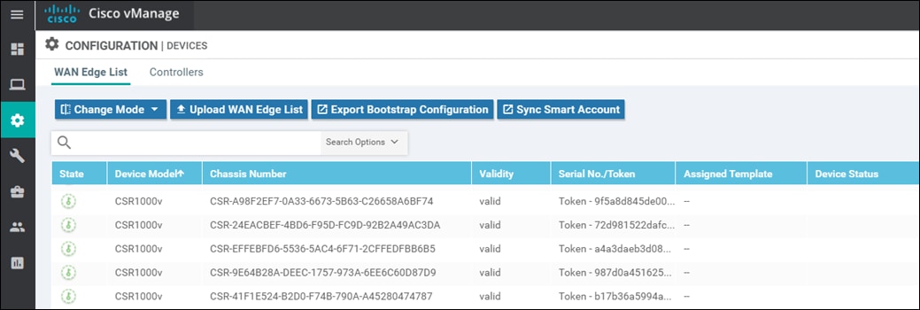
Step 3. Verify that you have at least two valid Cisco CSR 1000v routers and/or two valid Cisco vEdge Cloud routers, which are not being used already. Valid unused devices should have the word “valid” under the Validity column. The Assigned Template, Device Status, Hostname, System IP, and Site ID columns should be blank.
Cisco vEdge Cloud routers and Cisco CSR 1000v routers are sold as a software subscription license. Go to software.cisco.com and use the Plug and Play Connect portal to add tokens/licenses and sync or upload them to vManage if you have insufficient Cisco SD-WAN Edge software router tokens.
Procedure 3. Configure feature and device templates for the Cisco SD-WAN Edge routers that will be used in the transit VPCs
You must have at least a minimal device template assigned within Cisco vManage to the software tokens that represent the Cisco SD-WAN Edge routers that Cisco Cloud onRamp for IaaS provisions within the transit VPC. A minimal device template is one that uses factory default feature templates within the device template. You will need at least one service VPN and the Management (VPN 512) interface configured within the device template. However, following the design paradigm that cloud infrastructure should be immutable, it is recommended that you configure fully functional device templates - which includes settings specific to your deployment within custom feature templates - when deploying transit VPCs.
You can use different device templates for each pair of Cisco CSR 1000v or Cisco vEdge Cloud routers instantiated in a single transit VPC – if you instantiate multiple pairs of Cisco SD-WAN Edge routers within a single transit VPC. Likewise, you can use different device templates for each Cisco CSR 1000v or Cisco vEdge Cloud router pair instantiated within different transit VPCs. However, using a single device template (with different variables configured per device as appropriate) standardizes the deployment of the Cisco CSR 1000v and/or Cisco vEdge Cloud instances within and across transit VPCs.
For this deployment guide the following device templates are used for devices within the transit VPCs:
Cisco CSR 1000v routers: saville-CSR1000v_Cloud_OnRamp_Transit_VPC,
Cisco vEdge Cloud routers: saville-vEdge_Cloud_OnRamp_Transit_VPC
Both device templates are created from custom feature templates. The naming of the device and feature templates within this deployment guide follows a convention which reflects the following:
● The userid of the administrator who created the template
● The device type (Cisco IOS XE SD-WAN device or vEdge device) for which the template should be applied
● The function of the template
The device templates, as well as the various feature templates which make up each device template, are discussed in Appendix C.
Please refer to the Cisco SD-WAN Deployment Guide located at the following URL, for step-by-step instructions as to how to create individual feature templates and device templates within Cisco vManage.
https://www.cisco.com/c/dam/en/us/td/docs/solutions/CVD/SDWAN/SD-WAN-End-to-End-Deployment-Guide.pdf
Procedure 4. Attach the device templates to the software tokens representing the Cisco SD-WAN Edge routers that will be used in the transit VPC
When you attach a device template to Cisco CSR 1000v or vEdge Cloud routers, Cisco vManage builds the configuration based on the feature templates and then associates the configuration with the software tokens representing the Cisco SD-WAN Edge routers that will be used in the transit VPC. For Cisco CSR 1000v and vEdge Cloud routers, the configuration, along with a One-Time Password (OTP) – unique to each device, are included within the cloud-init file. The OTP is used by the Cisco CSR 1000v or vEdge Cloud router to initially authenticate to the Cisco vBond and vManage controllers. The cloud-init file is uploaded to AWS as User Data when the Cisco CSR 1000v and/or vEdge Cloud routers are instantiated.
However, before the configuration can be built and pushed out, you need to first define all variables within the feature templates attached to the device template. There are two ways to do this, either by entering in the values of the variables manually within the GUI, or by uploading a .csv file with a list of the variables and their values. Both methods are discussed within the Cisco SD-WAN Deployment Guide referenced earlier. This section of the deployment guide will only discuss entering values manually.
The following are the steps:
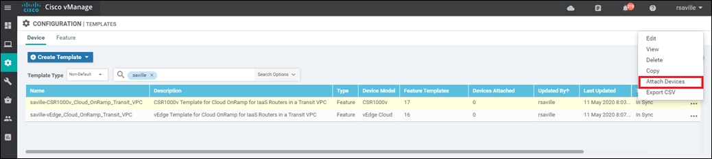
Step 1. Go to Configuration > Templates and select the Device tab.
Step 2. Find the desired device template.
The example within this section will highlight the steps for deploying the device template named saville-CSR1000v_Cloud_onRamp_Transit_VPC to Cisco CSR 1000v routers. The steps are similar for deploying the device template named saville-vEdge_Cloud_onRamp_Transit_VPC to Cisco vEdge Cloud routers.
Step 3. Select the … to the right of the template, and from the drop-down menu select Attach Devices.
An example is shown in the following figure.
A pop-up window listing the available devices to be attached to this configuration will appear. The list of available devices will contain either the hostname and IP address of a device, if it is known through Cisco vManage; or the chassis serial number of a device, if it has not yet come up on the network and is unknown by Cisco vManage. Cisco CSR 1000v and Cisco vEdge Cloud routers are assigned a chassis serial number although there is no physical chassis. The list contains only the device model that was defined when the template was created (for this deployment guide, Cisco CSR 1000v or Cisco vEdge Cloud routers).
Step 4. Select the devices you want to apply the configuration template to and select the arrow to move the device from the Available Devices box to the Selected Devices box.
You can select multiple devices at one time by simply clicking each desired device.
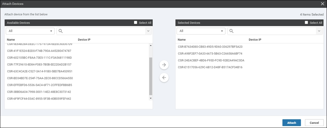
Step 5. Click the Attach button.
A new screen will appear, listing the devices that you have selected. An example is shown in the following figure.
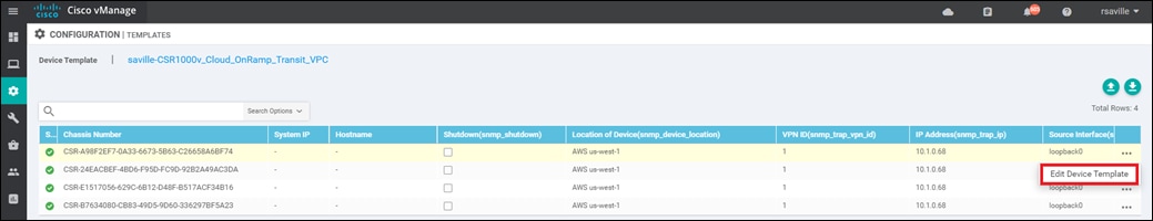
Step 6. Find the first Cisco SD-WAN Edge device, select … to the far right of it, and from the drop-down menu select Edit Device Template.
A pop-up screen will appear with a list of variables and empty text boxes. There may also be variables with check boxes to check/uncheck for on/off values. An example is shown in the figure below.
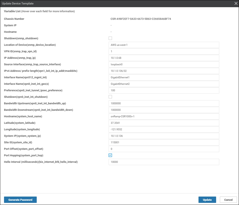
Step 7. Fill in the values of the variables in the text boxes.
All text fields must be filled in. If you leave a text field empty, the box around the text field will be highlighted red when you try to move to the next page. Check boxes can be left unchecked. For check boxes, checked means “Yes” and unchecked means “No”.
The device templates for Cisco CSR 1000v routers and vEdge Cloud routers were slightly different for this deployment guide.
Cisco CSR 1000v routers
The following tables show the variables used when deploying the first device pair (Device Pair #1) of Cisco CSR 1000v routers for this deployment guide.
Table 1. onRamp-CSR1000v-1 device template variable values
| Variable |
Value |
| Shutdown (snmp_shutdown) |
□ |
| Location of Device(snmp_device_location) |
AWS us-west-1 |
| VPN ID (snmp_trap_vpn_id) |
1 |
| IP Address(snmp_trap_ip) |
10.1.0.68 |
| Source Interface(snmp_trap_source_interface) |
loopback0 |
| IPv4 Address/prefix length(vpn1_lo0_int_ip_addr|maskbits) |
10.1.0.136/32 |
| Interface Name(vpn512_mgmt_int) |
GigabitEthernet1 |
| Interface Name(vpn0_inet_int_gex|x) |
GigabitEthernet2 |
| Preference (vpn0_inet_tunnel_ipsec_preference) |
100 |
| Shutdown (vpn0_inet_int_shutdown) |
□ |
| Bandwidth Upstream (vpn0_inet_int_bandwidth_up) |
1000000 |
| Bandwidth Downstream (vpn0_inet_int_bandwidth_down) |
1000000 |
| Hostname (system_host_name) |
onRamp-CSR1000v-1 |
| Latitude (system_latitude) |
37.3541 |
| Longitude(system_longitude) |
-121.9552 |
| System IP (system_system_ip) |
10.1.0.136 |
| Site ID (system_site_id) |
115001 |
| Port Offset (system_port_offset) |
0 |
| Port Hopping (system_port_hop) |
✓ |
| VPN ID (logging_server_vpn) |
1 |
| Hello Interval (milliseconds) (bfd_biz_internet_hello_interval) |
10000 |
Table 2. onRamp-CSR1000v-2 device template variable values
| Variable |
Value |
| Shutdown (snmp_shutdown) |
□ |
| Location of Device(snmp_device_location) |
AWS us-west-1 |
| VPN ID(snmp_trap_vpn_id) |
1 |
| IP Address(snmp_trap_ip) |
10.1.0.68 |
| Source Interface(snmp_trap_source_interface) |
loopback0 |
| IPv4 Address (vpn1_lo0_int_ip_addr|maskbits) |
10.1.0.137/32 |
| Interface Name (vpn512_mgmt_int) |
GigabitEthernet1 |
| Interface name (vpn0_inet_int_gex|x) |
GigabitEthernet2 |
| Preference (vpn0_inet_tunnel_ipsec_preference) |
100 |
| Shutdown (vpn0_inet_int_shutdown) |
□ |
| Bandwidth Upstream (vpn0_inet_int_bandwidth_up) |
1000000 |
| Bandwidth Downstream (vpn0_inet_int_bandwidth_down) |
1000000 |
| Hostname (system_host_name) |
onRamp-CSR1000v-2 |
| Latitude (system_latitude) |
37.3541 |
| Longitude(system_longitude) |
-121.9552 |
| System IP (system_system_ip) |
10.1.0.137 |
| Site ID (system_site_id) |
115001 |
| Port Offset (system_port_offset) |
0 |
| Port Hopping (system_port_hop) |
✓ |
| VPN ID (logging_server_vpn) |
1 |
| Hello Interval (milliseconds) (bfd_biz_internet_hello_interval) |
10000 |
Configuration variables for additional CSR 1000v router device pairs (Device Pair #2, Device Pair #3, and Device Pair #4) are similar but not shown in this guide.
Interface names for Cisco CSR 1000v routers start with GigabitEthernet1. Subsequent interfaces follow the standard conventions for Cisco IOS XE devices – GigabitEthernet2, GigabitEthernet3, etc. This is different from Cisco vEdge Cloud routers.
For CSR 1000v routers, GigabitEthernet1 must be assigned to the out-of-band management interface (VPN 512) when using Cisco Cloud onRamp for IaaS. GigabitEthernet2 must be assigned to the transport VPN interface (VPN 0) when using Cisco Cloud onRamp for IaaS. The transit VPC has no service side network interface. If you configure GigabitEthernet1 as the transport VPN interface (VPN0), when you map the host VPCs to the transit VPC within Cisco Cloud onRamp for IaaS, the host VPC site-to-site IPsec VPN tunnels may not come up.
For this deployment guide, the first pair of Cisco CSR 1000v routers (Device Pair #1) is assigned Site ID 115001. The second pair of Cisco CSR 1000v routers (Device Pair #2 – not shown in tables above) is assigned Site ID 115002. This is one of the methods which can be used to allow host VPC to host VPC routing via the transit VPC when different host VPCs are mapped to different pairs of Cisco CSR 1000v routers within the transit VPC. Please see the Site ID Configuration when Multiple Device Pairs are Implemented per Transit VPC section within the Design chapter of this deployment guide for details.
Cisco vEdge Cloud routers
The following tables show the variables used when deploying the first device pair (Device Pair #1) of Cisco vEdge Cloud routers for this deployment guide.
Table 3. onRamp-vEdgeCloud-1 device template variable values
| Variable |
Value |
| Shutdown (snmp_shutdown) |
□ |
| Location of Device(snmp_device_location) |
AWS us-west-1 |
| VPN ID (snmp_trap_vpn_id) |
1 |
| IP Address(snmp_trap_ip) |
10.1.0.68 |
| Source Interface(snmp_trap_source_interface) |
loopback0 |
| IPv4 Address/prefix length(vpn1_lo0_int_ip_addr|maskbits) |
10.1.0.138/32 |
| Interface Name(vpn512_mgmt_int) |
eth0 |
| Interface Name(vpn0_inet_int_gex|x) |
ge0/0 |
| Preference (vpn0_inet_tunnel_ipsec_preference) |
100 |
| Shutdown (vpn0_inet_int_shutdown) |
□ |
| Bandwidth Upstream (vpn0_inet_int_bandwidth_up) |
1000000 |
| Bandwidth Downstream (vpn0_inet_int_bandwidth_down) |
1000000 |
| Hostname (system_host_name) |
onRamp-vEdge-Cloud-1 |
| Latitude (system_latitude) |
37.3541 |
| Longitude(system_longitude) |
-121.9552 |
| System IP (system_system_ip) |
10.1.0.138 |
| Site ID (system_site_id) |
115001 |
| Port Offset (system_port_offset) |
0 |
| Port Hopping (system_port_hop) |
✓ |
| VPN ID (logging_server_vpn) |
1 |
| Hello Interval (milliseconds) (bfd_biz_internet_hello_interval) |
10000 |
Table 4. onRamp-vEdgeCloud-2 device template variable values
| Variable |
Value |
| Shutdown (snmp_shutdown) |
□ |
| Location of Device(snmp_device_location) |
AWS us-west-1 |
| VPN ID(snmp_trap_vpn_id) |
1 |
| IP Address(snmp_trap_ip) |
10.1.0.68 |
| Source Interface(snmp_trap_source_interface) |
loopback0 |
| IPv4 Address (vpn1_lo0_int_ip_addr|maskbits) |
10.1.0.139/32 |
| Interface Name (vpn512_mgmt_int) |
eth0 |
| Interface name (vpn0_inet_int_gex|x) |
ge0/0 |
| Preference (vpn0_inet_tunnel_ipsec_preference) |
100 |
| Shutdown (vpn0_inet_int_shutdown) |
□ |
| Bandwidth Upstream (vpn0_inet_int_bandwidth_up) |
1000000 |
| Bandwidth Downstream (vpn0_inet_int_bandwidth_down) |
1000000 |
| Hostname (system_host_name) |
onRamp-vEdge-Cloud-2 |
| Latitude (system_latitude) |
37.3541 |
| Longitude(system_longitude) |
-121.9552 |
| System IP (system_system_ip) |
10.1.0.139 |
| Site ID (system_site_id) |
115001 |
| Port Offset (system_port_offset) |
0 |
| Port Hopping (system_port_hop) |
✓ |
| Hello Interval (milliseconds) (bfd_biz_internet_hello_interval) |
10000 |
Configuration variables for additional Cisco vEdge Cloud router device pairs (Device Pair #2, Device Pair #3, and Device Pair #4) are similar but not shown in this guide.
The interface names for Cisco vEdge Cloud routers include eth0, and then begin with ge0/0 for subsequent interfaces. This is different from Cisco CSR 1000v routers.
For Cisco vEdge Cloud routers, eth0 must be assigned to the out-of-band management interface (VPN 512) when using Cisco Cloud onRamp for IaaS. Interface ge0/0 must be assigned to the transport VPN interface (VPN 0) when using Cisco Cloud onRamp for IaaS. The transit VPC has no service side network interface.
As with the CSR 1000v routers, the first pair of Cisco vEdge Cloud routers (Device Pair #1) is assigned Site ID 115001. The second pair of Cisco vEdge Cloud routers is assigned Site ID,115002. This is one method which can be used to allow host VPC to host VPC routing via the transit VPC when different host VPCs are mapped to different pairs of Cisco vEdge Cloud routers within the transit VPC. Please see the Site ID Configuration when Multiple Device Pairs are Implemented per Transit VPC section within the Design chapter of this deployment guide for details.
Step 8. When you have filled in the values of the variables in the text boxes, select Update.
This will fill in all the variables for the template for the first Cisco SD-WAN Edge router.
Step 9. Repeat Steps 6 – 8 for each subsequent Cisco SD-WAN Edge router.
Step 10. Download the .csv file
When you are finished filling out the variables and before moving further, download the .csv file by selecting the download arrow symbol in the upper right corner.
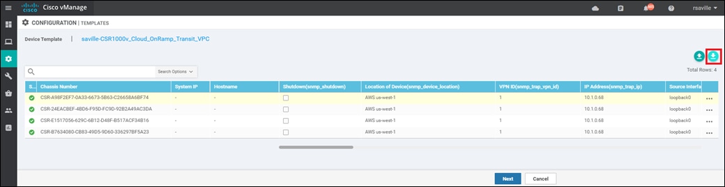
The .csv file will be populated with the values you have filled in so far. If you deploy the configuration, and for any reason there is an error in one of the input variables, the configuration may fail to deploy. When you come back to this page, all the values will be gone, and you will need to enter them in again.
If you downloaded the populated .csv file, just upload it by selecting the up arrow. Then you can select … to the right of the desired device and select Edit Device Template, and your latest values will be populated in the text boxes. You can then modify any input values and try to deploy again.
Step 11. When you are ready to deploy, select the Next button.
The next screen will indicate that the template (or templates if you used multiple device templates) will be applied to the devices. An example is shown in the figure below.
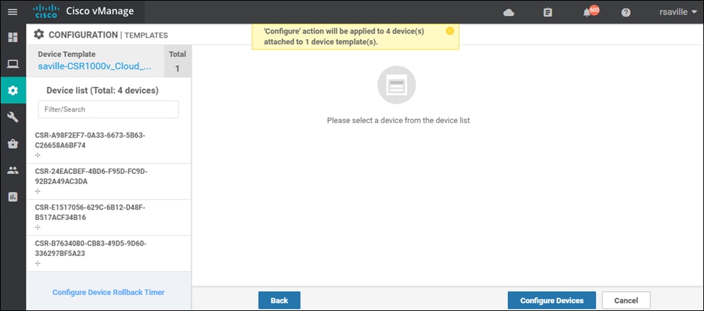
If you forget to add values for a device, you will get an error and you won't be able to move forward until that is corrected.
Selecting any device in the left-hand panel will show you the configuration that will be pushed to that Cisco SD-WAN Edge device (through the Config Preview tab).
Appendix D shows the configuration pushed to one of the Cisco CSR 1000v routers (onRamp-CSR1000v-1) and one of the Cisco vEdge Cloud routers(onRamp-vEdge-Cloud-1) from the configuration templates.
Step 12. Click on the Configure Devices button.
A pop-up window will appear, informing you that committing the changes will affect the configuration on the Cisco SD-WAN Edge devices, and asking you to confirm that you want to proceed.
Step 13. Check the box next to Confirm configuration changes on 4 devices and click on the OK button.
| Tech tip |
| Device templates must be attached to a minimum of two software tokens and up to a maximum of eight software tokens representing Cisco CSR 1000v or Cisco vEdge routers, per transit VPC. The screen captures within this procedure show device templates being attached to four software tokens representing Cisco CSR 1000v routers. |
The Task View screen will then appear. After a few moments the status of the Cisco SD-WAN Edge routers will appear as “Done – Scheduled” with a message indicating that the device is offline and that the template will be attached to the device when it comes online. An example is shown in the figure below.
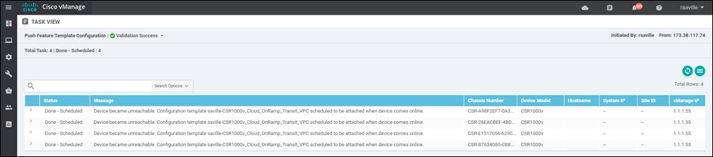
The Cisco SD-WAN Edge routers are now ready to be deployed within the AWS transit VPC by Cisco Cloud onRamp for IaaS.
Process: Deploy a transit VPC with Cisco Cloud onRamp for IaaS
This section discusses the procedures for deploying a transit VPC using Cisco Cloud onRamp for IaaS with AWS.
Procedure 1. Login to Cisco vManage and navigate to Cloud onRamp for IaaS
Step 1. Login to the Cisco vManage web console using the IP address or fully qualified domain name of your Cisco vManage instance.
For example: https://Cisco_vManage_ip_addr_or_FQDN:8443/
This will bring up the Cisco vManage dashboard, as shown in the following figure.
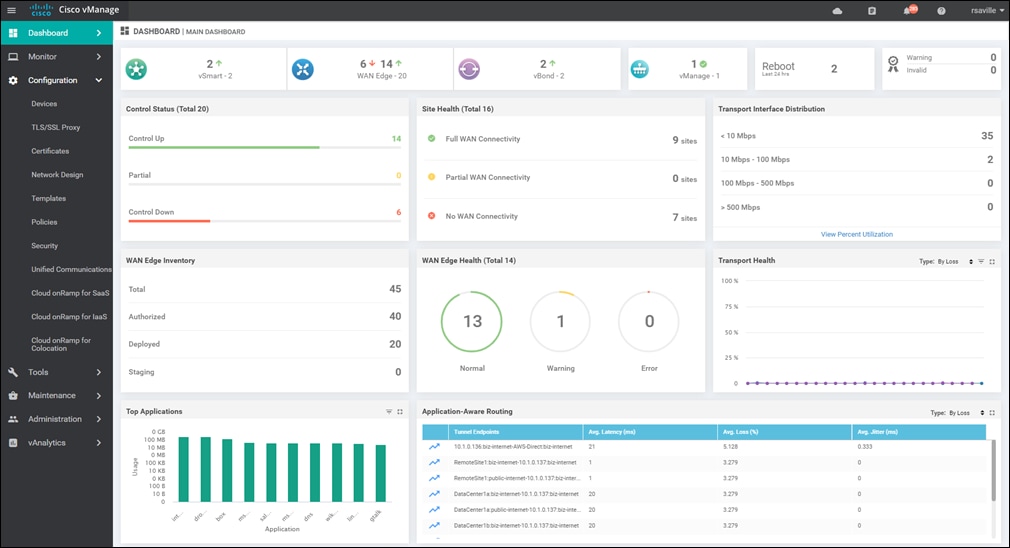
Step 2. In the navigation panel on the left side of the screen, select Configuration > Cloud onRamp for IaaS.
This will bring you to the initial Cisco Cloud onRamp for IaaS screen, as shown in the figure below.
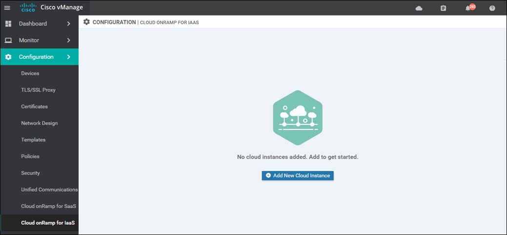
If this is the first time you are configuring Cisco Cloud onRamp for IaaS, no cloud instances will appear within the screen. A cloud instance corresponds to an AWS account with one or more transit VPCs created within an AWS region.
You must have at least two unused Cisco SD-WAN Edge virtual router software tokens (Cisco CSR 1000v or vEdge Cloud), with templates attached, available in Cisco vManage to proceed with this step. Otherwise, an error message will appear at the top of the initial Cisco Cloud onRamp for IaaS screen, and you will not be able to continue.
Procedure 2. Select the cloud provider and configure access credentials
Step 1. Click the Add New Cloud Instance button.
This will begin the workflow for you to add a new cloud instance. The following pop-up screen will appear.
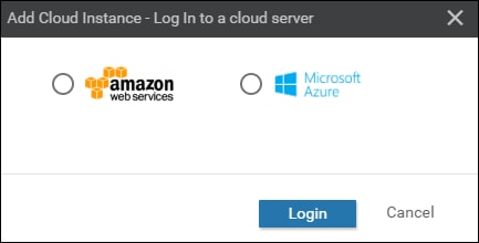
A radio button will allow you to select one of the supported cloud providers.
| Tech tip |
| As of Cisco vManage platform version 20.1.1, two cloud providers are supported – Amazon Web Services (AWS) and Microsoft Azure. |
This deployment guide discusses AWS as the cloud provider.
Step 2. Select the Amazon Web Services radio button.
The pop-up screen will change as shown in the figure below.
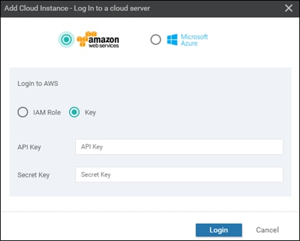
Cisco Cloud onRamp for IaaS uses API calls to create the AWS transit VPC, instantiate Cisco SD-WAN Edge router instances within the transit VPC, and to map existing AWS host VPCs to the transit VPC. Either an AWS Identity and Management (IAM) Role or an Access Key can be used to make the necessary API calls. For ease of reading, this document will simply refer to either of these as AWS credentials.
The use of Access Keys with Cisco Cloud onRamp for IaaS is not recommended. Access Keys allow access to the full privileges of your AWS account, including the ability to add/delete users to your account if you have such privileges. The use of an IAM Role allows you to restrict the privileges granted to those who assume that role. For Cisco Cloud onRamp for IaaS, the IAM Role requires full VPC and EC2 privileges in order to make the necessary API calls to create (and destroy) the transit VPC, as well as the EC2 instances which support the Cisco SD-WAN Edge routers.
This deployment guide uses an IAM Roles for AWS credentials. Appendix F discusses how to create an IAM role and grant it the necessary privileges.
Step 3. Click the IAM Role radio button.
The pop-up screen will change to look like the following figure.
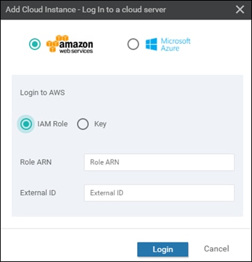
Step 4. Enter your Role ARN and External ID in the text fields and click Login.
| Tech tip |
| If you used Access Keys and if you get an error message indicating the user does not have the required permissions when you entered the API key, this may be the result of the Cisco vManage server not being time-synced with an NTP server. |
Procedure 3. Add a transit VPC
Upon entering your AWS credentials, you will be taken to the next step in the workflow – adding a transit VPC. An example of the Add Transit VPC screen is shown in the figure below.
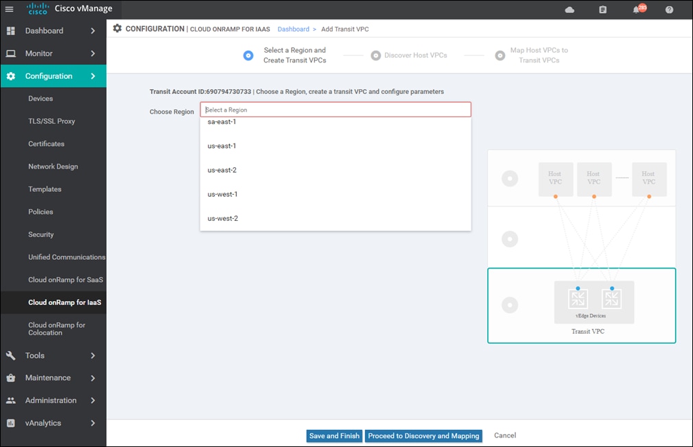
Step 1. From the drop-down menu next to Choose a Region, select the AWS region in which you want to create a transit VPC.
For this deployment guide, the transit VPC is created in the us-west-1 (N. California) region. Once you select the AWS region the screen will change as shown in the following figure.
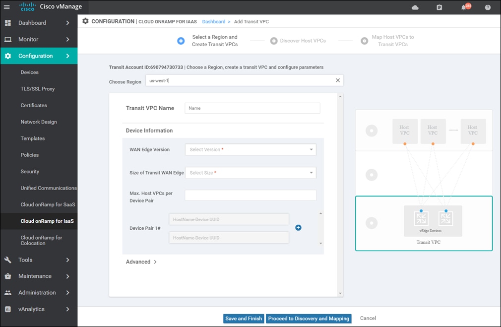
Step 2. Fill in the information for the transit VPC.
This step has two options – depending upon whether you are deploying Cisco CSR 1000v routers or Cisco vEdge Cloud routers within the transit VPC. Select the option appropriate for your deployment.
Option 1: Cisco CSR 1000v routers
The following shows the information for the transit VPC using Cisco CSR 1000v routers, created for this section of the deployment guide.
Transit VPC Name: Cloud_onRamp_Transit_VPC1
This is the name of the transit VPC to be created by Cisco Cloud onRamp within AWS.
WAN Edge Version:
This is the version of software which will be run by one or more redundant pairs of Cisco CSR 1000v routers running within the transit VPC. Cisco vManage will list the software versions that are available for Cisco CSR 1000v routers, based upon the vManage software release.
The latest software version for Cisco CSR 1000v routers available on vManage release 20.1.1 when this deployment guide was written was selected as follows:
● Cisco CSR 1000v: csr-Cisco-CSR-SDWAN-17.2.1v-8ffa16cf-1756-44a2-9e95-2b4369bb2fe9-ami-0ff6c52e98575a5df.4
Size of Transit vEdge:
For this deployment guide, the EC2 instance size listed as "Vendor Recommended" for the Cisco CSR 1000v router AMI within the AWS Marketplace, was selected :
● CSR 1000v – c4.large
Cisco vManage will display the sizes of the EC2 compute platforms available in the drop-down list adjacent to Size of Transit vEdge. For Cisco vManage release 20.1.1, these are the choices:
● c3.large (2 vCPU)
● c4.large (2 vCPU)
● c3.xlarge (4 vCPU)
● c4.xlarge (4 vCPU)
● c3.2xlarge (8 vCPU)
● c4.2xlarge (8 vCPU)
The EC2 instances available for various versions of the Cisco CSR 1000v routers displayed within Cisco Cloud onRamp for IaaS may not line up with the available EC2 instances for their respective AMIs within AWS – for the particular region in which you plan to deploy the transit VPC. You should first consult the AWS Marketplace, at the following URL, for the Cisco CSR 1000v routers which you will be deploying in a transit VPC through Cisco Cloud onRamp for IaaS, to determine the available EC2 instance types for the AWS region in which you plan to deploy the transit VPC.
https://aws.amazon.com/marketplace/pp/B07S4CPR3Y?qid=1589557639191&sr=0-5&ref_=srh_res_product_title
For example, as of the time this document was written, C3 instances are not an option for the Cisco Cloud Services Router (CSR) 1000V - BYOL for SD-WAN AMI on the AWS Marketplace for the US West (N California) region. Only c4 and c5 compute optimized instances are available (as well as t2.medium). However, as of Cisco vManage release 20.1.1, c5 compute optimized instances are not an option to select within Cisco vManage for Cisco CSR 1000v routers. Therefore, you must choose one of the supported c4 instance sizes for Cisco CSR 1000v routers when using Cisco Cloud onRamp for IaaS.
Generally, the larger the instance, the more vCPUs, memory, and network performance you have – but at a higher per hour rate. Please see the following URL for the hourly rates for various AWS EC2 instances:
https://aws.amazon.com/ec2/pricing/on-demand/
You should select the appropriate instances for your Cisco CSR 1000v routers based on your requirements for performance and cost within your transit VPC. For this deployment guide overall scale and performance through the transit VPC has not been validated.
Max. Host VPCs per Device Pair:
This is the maximum number of host VPCs that can be attached to a single Cisco CSR 1000v router device pair within the transit VPC. The range is from 1 to 32.
This parameter controls the Cisco Cloud onRamp for IaaS auto scaling feature, in conjunction with the number of device pairs assigned to the transit VPC. When Cisco Cloud onRamp for IaaS creates the transit VPC, it will instantiate Device Pair #1. As host VPCs are added to the transit VPC, they will be mapped to Device Pair #1 up to the Max. Host VPCs per Device Pair number. When the next host VPC is mapped to the transit VPC (exceeding the Max. Host VPCs per Device Pair number configured) Cisco Cloud onRamp for IaaS will automatically instantiate the next pair of Cisco CSR 1000v routers (Device Pair #2) before mapping the host VPC to the new device pair – if you have configured a second Cisco CSR 1000v device pair. Likewise, when the number of host VPCs mapped to Device Pair #2 exceed the Max. Host VPCs per Device Pair number, when the next host VPC is mapped to the transit VPC, Cisco Cloud onRamp for IaaS will automatically instantiate the next pair of Cisco CSR 1000v routers (Device Pair #3) before mapping the host VPC to the new device pair – if you have configured a third Cisco CSR 1000v device pair.
You can configure up to four Cisco SD-WAN Edge device pairs per transit VPC. They must all be the same type of SD-WAN Edge router (either all Cisco vEdge Cloud routers or all Cisco CSR 1000v routers) and they must all run the same software version. You cannot mix-and-match Cisco vEdge Cloud routers and Cisco CSR 1000v routers within a single transit VPC.
Device Pair 1#:
Unused Cisco SD-WAN Edge instances within vManage - which have templates attached - will appear in the drop-down menus of the boxes adjacent to Device Pair 1#. The instances displayed will match the type for the WAN Edge Version selected. For example if a Cisco CSR 1000v version is selected, then only available Cisco CSR 1000v instances will appear in the drop-down menus.
Device Pair 2#:
In order to add a second device pair you must click the “+” next to Device Pair #1. This will add a field allowing you to add an additional device pair, Device Pair #2. You can repeat this up to four device pairs per transit VPC.
The following are additional fields which can be accessed by clicking on the “>” sign next to Advanced.
Transit VPC CIDR:
The default IPv4 CIDR for the transit VPC is 10.0.0.0/16. This deployment guide uses a smaller IPv4 CIDR from the RFC 1918 address space – 192.168.104.0/24. The supported range of IPv4 CIDR blocks is from /16 to /25. There must be sufficient address space within the IPv4 CIDR block for Cisco Cloud onRamp for IaaS to create 6 subnets. Cisco Cloud onRamp for IaaS will automatically subnet the IPv4 CIDR block by shifting the bit position over by 3 bits. For example, if a /16 IPv4 CIDR block is specified for the transit VPC, Cisco Cloud onRamp for IaaS will create 6 subnets within the IPv4 CIDR block, with each subnet having a /19 mask. Likewise, if a /24 IPv4 CIDR block is specified for the transit VPC, Cisco Cloud onRamp for IaaS will create 6 subnets within the IPv4 CIDR block, with each subnet having a /27 mask.
Three of the subnets will be attached to one of the Cisco SD-WAN Edge routers of a redundant pair within the transit VPC – in one AWS availability zone. The other three subnets will be attached to the other Cisco SD-WAN Edge router of a redundant pair within the transit VPC – in another AWS availability zone. Therefore, if one AWS availability zone has an outage, at least one of the Cisco SD-WAN Edge routers within the transit VPC will be unaffected. Additional pairs of SD-WAN Edge routers instantiated within the transit VPC will use the same subnets.
Only IPv4 addressing is supported. AWS currently supports only IPv4 addressing for Site-to-Site VPN connections that connect the transit VPC to host VPCs.
SSH PEM Key:
By default, AWS EC2 instances are accessed using an SSH keypair. This is different from the AWS credentials discussed earlier. You must have an SSH keypair already configured under the same userid used for the AWS credentials discussed earlier. See Appendix G for instructions on generating an SSH keypair.
From the drop-down menu next to SSH PEM Key, select the keypair used to access the Cisco CSR 1000v routers which will be created within the transit VPC. For this deployment guide, the keypair named IaaS_OnRamp was used.
Option 2: Cisco vEdge Cloud routers
The following details the information for the transit VPC using Cisco vEdge Cloud routers, created for this deployment guide.
Transit VPC Name: Cloud_onRamp_Transit_VPC1
This is the name of the transit VPC created by Cisco Cloud onRamp within AWS.
WAN Edge Version:
This is the version of software which will run on the redundant pair of Cisco vEdge Cloud routers running within the transit VPC. Cisco vManage will list the software versions that are available for Cisco vEdge Cloud routers, based upon the software version of vManage.
The latest software version for Cisco vEdge Cloud routers available on vManage release 20.1.1, when this deployment guide was written was selected as follows:
● Cisco vEdge Cloud: vEdge-19.3.0
Size of Transit vEdge:
For this deployment guide, the EC2 instance size listed as "Vendor Recommended" for the Cisco vEdge Cloud router AMI within the AWS Marketplace, at the time this document was written, was selected :
● Cisco vEdge Cloud – c3.large
Cisco vManage will display the sizes of the EC2 compute platforms available in the drop-down list adjacent to Size of Transit vEdge. As of the time this document was written, these are the choices:
● c3.large (2 vCPU)
● c4.large (2 vCPU)
● c3.xlarge (4 vCPU)
● c4.xlarge (4 vCPU)
● c3.2xlarge (8 vCPU)
● c4.2xlarge (8 vCPU)
The EC2 instances available for various versions of the Cisco vEdge Cloud routers displayed within Cisco vManage may not line up with the available EC2 instances for their respective AMIs within AWS – for the particular region in which you plan to deploy the transit VPC. You should first consult the AWS Marketplace, at the following URL, for the Cisco vEdge Cloud routers which you will be deploying in a transit VPC using Cisco Cloud onRamp for IaaS, to determine the available EC2 instance types for the AWS region in which you plan to deploy the transit VPC.
https://aws.amazon.com/marketplace/pp/B07BZ53FJT?qid=1598384412722&sr=0-1&ref_=srh_res_product_title
For example, as of Cisco vManage release 20.1.1, although c5 compute optimized instances are an option for the Cisco vEdge Cloud Router within the AWS Marketplace, they are not an option to select within Cisco vManage for Cisco vEdge Cloud routers. Therefore, you must choose one of the supported c3, or c4 instance sizes for Cisco vEdge Cloud routers.
Generally, the larger the instance, the more vCPUs, memory, and network performance you have – but at a higher hourly rate. Please see the following URL for the hourly rate for various AWS EC2 instances:
https://aws.amazon.com/ec2/pricing/on-demand/
You should select the appropriate instances for your Cisco vEdge Cloud routers based on your requirements for performance and cost within your transit VPC. For this deployment guide overall performance through the transit VPC has not been validated.
Max. Host VPCs per Device Pair:
This is the maximum number of host VPCs that can be attached to a single Cisco vEdge Cloud router device pair within the transit VPC. The range is from 1 to 32.
This parameter controls the auto scaling feature, in conjunction with the number of Cisco vEdge Cloud device pairs assigned to the transit VPC. When Cisco Cloud onRamp for IaaS creates the transit VPC, it will instantiate Device Pair #1. As host VPCs are added to the transit VPC, they will be mapped to Device Pair #1 up to the Max. Host VPCs per Device Pair number. When the next host VPC is mapped to the transit VPC (exceeding the Max. Host VPCs per Device Pair number configured) Cisco Cloud onRamp for IaaS will automatically instantiate the next pair of Cisco vEdge Cloud routers (Device Pair #2) before mapping the host VPC to the new device pair – if you have configured a second Cisco vEdge Cloud device pair. Likewise, when the number of host VPCs mapped to Device Pair #2 exceeds the Max. Host VPCs per Device Pair number, when the next host VPC is mapped to the transit VPC, Cisco Cloud onRamp for IaaS will automatically instantiate the next pair of Cisco vEdge Cloud routers (Device Pair #3) before mapping the host VPC to the new device pair – if you have configured a third Cisco vEdge Cloud device pair.
You can configure up to four device pairs per transit VPC. They must all be the same type of Cisco SD-WAN Edge router (either all Cisco vEdge Cloud routers or all Cisco CSR 1000v routers) and they must run the same software version. You cannot mix-and-match Cisco vEdge Cloud routers and Cisco CSR 1000v routers within a single transit VPC.
Device Pair 1#:
Unused Cisco SD-WAN Edge instances within vManage - which have templates attached - will appear in the drop-down menus of the boxes adjacent to Device Pair 1#. The instances displayed will match the type for the WAN Edge Version selected. For example if a Cisco vEdge Cloud router version is selected, then only available Cisco vEdge Cloud router instances will appear in the drop-down menus.
Device Pair 2#:
In order to add a second device pair you must click the “+” next to Device Pair #1. This will add a field allowing you to add an additional device pair, Device Pair #2. You can repeat this up to four device pairs per transit VPC.
The following are additional fields which can be accessed by clicking on the “>” sign next to Advanced.
Transit VPC CIDR:
The default IPv4 CIDR for the transit VPC is 10.0.0.0/16. This deployment guide uses a smaller IPv4 CIDR from the RFC 1918 address space – 192.168.104.0/24. The supported range of IPv4 CIDR blocks is from /16 to /25. There must be sufficient address space within the IPv4 CIDR block for Cisco Cloud onRamp for IaaS to create 6 subnets. Cisco Cloud onRamp for IaaS will automatically subnet the IPv4 CIDR block by shifting the bit position over by 3 bits. For example, if a /16 IPv4 CIDR block is specified for the transit VPC, Cisco Cloud onRamp for IaaS will create 6 subnets within the IPv4 CIDR block, with each subnet having a /19 mask. Likewise, if a /24 IPv4 CIDR block is specified for the transit VPC, Cisco Cloud onRamp for IaaS will create 6 subnets within the IPv4 CIDR block, with each subnet having a /27 mask.
Three of the subnets will be attached to one of the Cisco SD-WAN Edge routers of a redundant pair within the transit VPC – in one AWS availability zone. The other three subnets will be attached to the other Cisco SD-WAN Edge router of a redundant pair within the transit VPC – in another AWS availability zone. Therefore, if one AWS availability zone has an outage, at least one of the Cisco SD-WAN Edge routers within the transit VPC will be unaffected. Additional pairs of SD-WAN Edge routers instantiated within the transit VPC will use the same subnets.
Only IPv4 addressing is supported. AWS currently supports only IPv4 addressing for Site-to-Site VPN connections that connect the transit VPC to host VPCs.
SSH PEM Key:
By default, AWS EC2 instances are accessed using an SSH keypair. This is different from the AWS credentials discussed earlier. You must have an SSH keypair already configured under the same userid used for the AWS credentials discussed earlier. See Appendix G for instructions on generating an SSH keypair.
From the drop-down menu next to SSH PEM Key, select the keypair used to access the Cisco vEdge Cloud routers which will be created within the transit VPC. For this deployment guide, the key named IaaS_OnRamp was used.
Step 3. Click on the Save and Finish button to create the transit VPC
Once you have filled in the fields, you can choose to create just the transit VPC at this time by clicking on the Save and Finish button. Alternatively, you can choose to proceed to the discovery and mapping of host VPCs to the transit VPC by selecting the Proceed to Discovery and Mapping button. For this deployment guide, the host VPCs are mapped to the transit VPC in a separate procedure.
After a few minutes, the Task View screen should appear, confirming that the transit VPC with a redundant pair of Cisco SD-WAN Edge routers has been created within AWS.
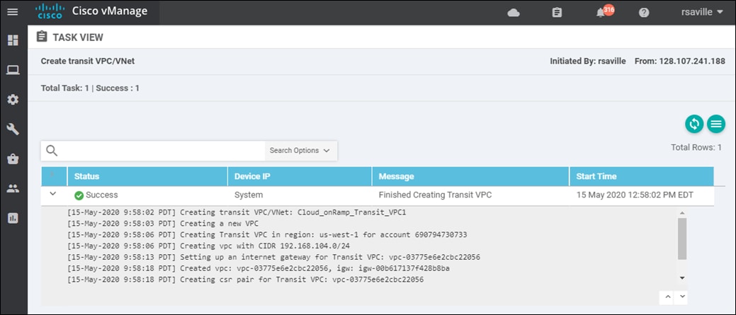
Process: Discover and map host VPCs to the transit VPC
This section discusses the procedures for discovering and mapping existing host VPCs to the transit VPC.
This document assumes the host VPCs are already created and ready to be mapped to the transit VPC. The creation of a host VPC is outside the scope of this document.
Procedure 1. Discover host VPCs
Before host VPCs can be mapped to the transit VPC, they must first be discovered within Cisco Cloud onRamp for IaaS.
Step 1. In the navigation panel on the left side of the screen, select Configuration > Cloud onRamp for IaaS.
This will bring you to the initial Cloud onRamp for IaaS screen, as shown in the figure below.
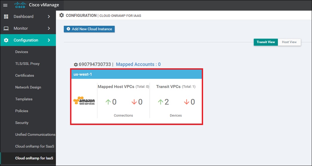
The cloud instance you created in the previous procedure will appear when the Transit View tab is selected. You can verify in which AWS region a particular cloud instance resides by clicking on the Mapped Accounts link for that particular cloud instance widget. Within the cloud instance shown in the figure above, a single transit VPC with two Cisco SD-WAN Edge routers has been created. Both Cisco SD-WAN Edge routers are up, as indicated by the green arrow.
| Tech tip |
| The Cisco SD-WAN Edge routers will show a status of up if they are able to establish connections to the vBond, vManage, and vSmart controllers. You must ensure the WAN Edge routers have reachability to the controllers. |
At this point, there are no host VPCs mapped to the transit VPC within the cloud instance. Host VPCs connect to the transit VPC through AWS Site-to-Site VPN connections that use elastic IP addresses (publicly routable IP addresses) at the transit VPC. Host VPCs must first be discovered and then mapped to the transit VPC.
Step 2. Click on the AWS cloud instance widget (area highlighted in red in the figure above) to which you wish to map host VPCs within the Cisco Cloud onRamp for IaaS screen.
This will bring up additional details regarding the cloud instance. An example is shown in the following figure.
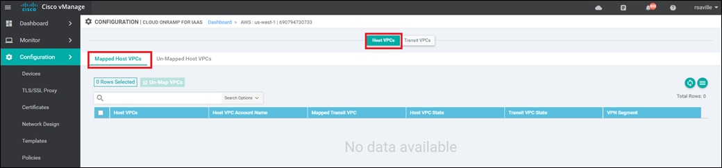
The details screen has two tabs - Host VPCs and Transit VPCs. In the figure above, the Host VPCs tab is selected. The Host VPCs tab has two sub-tabs - Mapped Host VPCs and Unmapped Host VPCs. By default, the Mapped Host VPCs sub-tab is selected. As can be seen in the figure above, no host VPCs are currently mapped to the transit VPC within the cloud instance.
Multiple transit VPCs can be configured within a single cloud instance (AWS account within a region). When multiple transit VPCs exist within a cloud instance, host VPCs can be mapped to any one of the transit VPCs.
Step 3. Select the Un-Mapped Host VPCs tab
The screen will change to look as shown in the figure below.
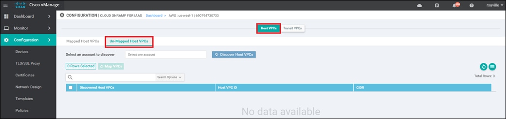
Host VPCs must first be discovered by Cisco Cloud onRamp for IaaS before they can be mapped to a transit VPC. The discovery process uses AWS API calls to discover the VPCs within the AWS account which you select. Note that only host VPCs within that account and within the same AWS region as the transit VPC will be discovered and displayed.
Step 4. From the drop-down menu next to Select one account - select the account from which you wish to discover host VPCs.
When you entered the AWS credentials within this deployment guide, the credentials were associated with an AWS account. The AWS account number associated with this account should appear within the drop-down menu. You can also enter new accounts by clicking in the New Account button at the bottom of the drop-down menu. A pop-up screen asking for the account credentials will appear, as shown in the figure below.
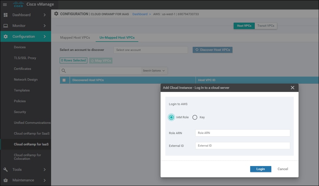
For this deployment guide, the host VPCs were created under the same account as the transit VPC.
Step 5. Click the Discover Host VPCs button
The screen should update to show the VPCs which are available to be mapped to a transit VPC. An example is shown in the following figure.
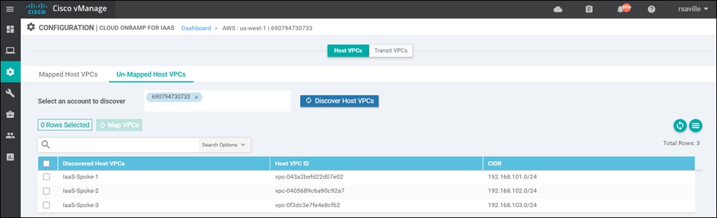
Only host VPCs within the AWS account selected and within the same AWS region as the transit VPC will appear.
VPCs must also have a Name tag associated with them within AWS, for them to appear within Cisco Cloud onRamp for IaaS. The default VPC automatically created by AWS for each region typically does not have a name tag associated with it. If you want the default VPC for the AWS region to appear within the list of VPCs to map to the transit VPC, you must assign a name tag to it within AWS before it can be discovered.
For the use case presented within the Design chapter of this deployment guide, two host VPCs - IaaS-Spoke-1 and IaaS-Spoke-2 – will be mapped to service VPN 1 in the transit VPC. Follow this, the third host VPC – IaaS-Spoke-3 – will be mapped to service VPN 2 in the transit VPC.
Procedure 2. Map the first two host VPCs to service VPN 1 in the transit VPC
Step 1. Select the first two host VPCs, IaaS-Spoke-1 and IaaS-Spoke-2, and click the Map VPCs button, as shown in the figure below.
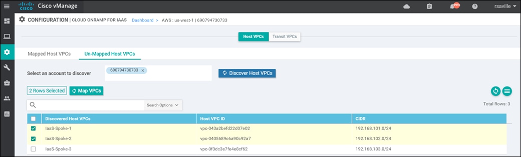
The following pop-up screen will appear.
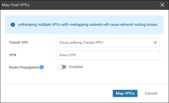
Step 2. Fill in the necessary fields as discussed below.
Transit VPC: Cloud_onRamp_Transit_VPC1
If there is only one transit VPC configured within the cloud instance, the Transit VPC field will be filled in for you. If there are multiple transit VPCs within the cloud instance, then select the transit VPC to which you wish to map the host VPC, from the drop-down menu.
Since there is only one transit VPC configured within the cloud instance currently for this deployment guide, Cloud_onRamp_Transit_VPC1, leave this field alone.
VPN: 1
In the drop-down menu next to VPN, you have the choice of mapping the host VPC to any of the service VPNs which you have defined within the device template attached to the Cisco SD-WAN Edge router instances.
Each host VPC can be mapped to a single service VPN. Mapping host VPCs to the same service VPN allows communication between the host VPCs – provided the associated AWS security groups and network ACLs allow it as well. Mapping host VPCs to different service VPNs provides network isolation (network segmentation) of the host VPCs from each other and allows only branch and campus sites with the same service VPN to access the host VPC.
Select 1 from the drop-down menu. This will map the first two host VPCs, IaaS-Spoke-1 and IaaS-Spoke-2 to service VPN 1 within the Cisco SD-WAN Edge routers deployed within the Cloud_onRamp_Transit_VPC1 VPC.
Route Propagation: Disabled
As discussed within the Transit VPC to Host VPC Routing section of the Design chapter of this deployment guide, OMP routes are not redistributed into BGP at the Cisco SD-WAN Edge routers within the transit VPC as of vManage release 20.1.1. Instead, network 0.0.0.0/0 is configured to be advertised by the Cisco SD-WAN Edge routers to the BGP peers representing the IPsec tunnel endpoints of the AWS Site-to-Site VPN Connections which are associated within the AWS Virtual Private Gateway (VGW) at each host VPC.
The Route Propagation setting determines whether network 0.0.0.0/0 is then propagated by the AWS Virtual Private Gateway (VGW) at each host VPC into the main route table of the host VPC. Route propagation also determines whether routes corresponding to subnets within the host VPCs are propagated amongst each other and are therefore visible to each other. Of course the host VPCs must be mapped to the same service VPN within the transit VPC, in order for these subnet routes to be visible to each other.
By default, Route Propagation is disabled, and for this deployment guide route propagation was left disabled. Subnets within the host VPCs were associated with user-defined route tables, rather than the default route table. A default route (0.0.0.0/0) was defined within the user-defined route tables pointing to the AWS Virtual Private Gateway (VGW). Outbound Internet access from the host VPCs was not configured for this deployment guide.
The Transit VPC to Host VPC Routing section of the Design chapter of this deployment guide discusses four scenarios depending upon whether route propagation is enabled or disabled and whether outbound Internet access from the host VPCs is required or not. You should choose which ever scenario is desired for your deployment and adjust the route propagation setting as appropriate.
Step 3. Click the Map VPCs button.
After a few minutes, the Task View screen should appear, confirming that the host VPCs have been mapped to the transit VPC.
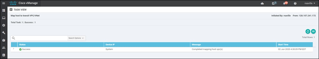
This completes the mapping of the first two host VPCs - IaaS-Spoke-1 and IaaS-Spoke-2 to service VPN 1.
You should be able to verify connectivity between EC2 instances with each of the first two host VPCs, IaaS-Spoke-1 and IaaS-Spoke-2, by establishing an SSH connection between them. Likewise, by configuring service VPN 1 on the first simulated branch (Branch 1) within this deployment guide, you should be able to verify connectivity to both host VPCs by establishing SSH connections from Branch 1 to the EC2 instances within the host VPCs. An example is shown in the following figure.
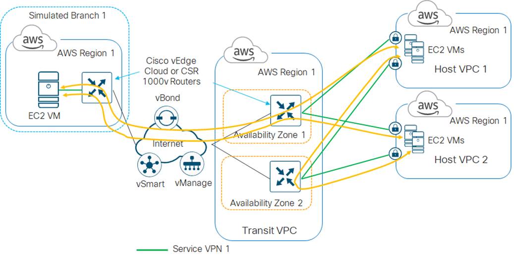
Procedure 3. Map the third host VPC to service VPN 2 in the transit VPC
Step 1. Repeat Procedure 1 to discover the third host VPC, IaaS-Spoke-3.
Step 2. Repeat Procedure 2 to map the third host VPC, IaaS-Spoke-3, to service VPN 2. The only difference will be the VPN number which you select.
You should be able to verify that connectivity between EC2 instances within either of the first two host VPCs, IaaS-Spoke-1 and IaaS-Spoke-2, and EC2 instances within the third host VPC, IaaS-Spoke-3 is not allowed. An SSH connection cannot be established between the EC2 instances.
Likewise, by configuring service VPN 2 on the second simulated branch (Branch 2) you should be able to verify connectivity to the third host VPC - IaaS-Spoke-3 - by establishing an SSH connection from Branch 2 to the EC2 instances within that host VPC. However, SSH connections from the Branch 2 to the EC2 instances within the first two host VPCs - IaaS-Spoke-1 and - IaaS-Spoke- 2 cannot be established. An example is shown in the following figure.
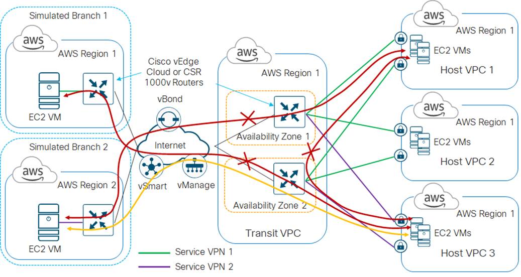
| Tech tip |
| If errors occur during the creation of the AWS transit VPC or the mapping of host VPCs to the transit VPC, such that the procedure cannot be completed, Cisco Cloud onRamp for IaaS will attempt to roll-back the configuration to the initial state. For example, if an AWS API call fails when trying to map a host VPC to the transit VPC, Cisco Cloud onRamp for IaaS will attempt to roll-back the configuration such that the host VPC will again appear as an unmapped host VPC, so that the procedure can be tried again. |
Procedure 4. (Optional) Modifying an existing transit VPC
This procedure is optional, and primarily included for information purposes. You can modify an existing transit VPC to do any of the following:
● Add another device pair to the transit VPC
● Change the maximum number of host VPCs that can be mapped to each device pair within the transit VPC
● Trigger the autoscaling feature to un-instantiate device pairs that no longer have any host VPCs mapped to them within the transit VPC
● Delete the transit VPC
The following steps show how to accomplish each of these.
Step 1. In the navigation panel on the left side of any vManage screen, select Configuration > Cloud onRamp for IaaS.
This will bring you to the initial Cloud onRamp for IaaS screen. An example was shown in the Figure 35 above.
Step 2. Click on the AWS cloud instance widget (area highlighted in red in the Figure 35 above) which you wish to modify.
This will bring up additional details regarding the cloud instance. The details screen has two tabs - Host VPCs and Transit VPCs.
Step 3. Select the Transit VPCs tab.
The screen will change to display the existing transit VPC which you have provisioned and to which you have mapped host VPCs.
Step 4. Click the … icon to the right of the transit VPC to display the drop-down menu as show in the following figure.
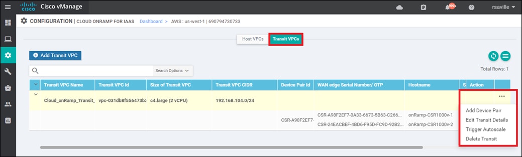
Step 5. To add additional device pairs to the existing transit VPC, click Add Device Pair from the drop-down menu.
The Add Device Pairs pop-up window will appear, as shown below.
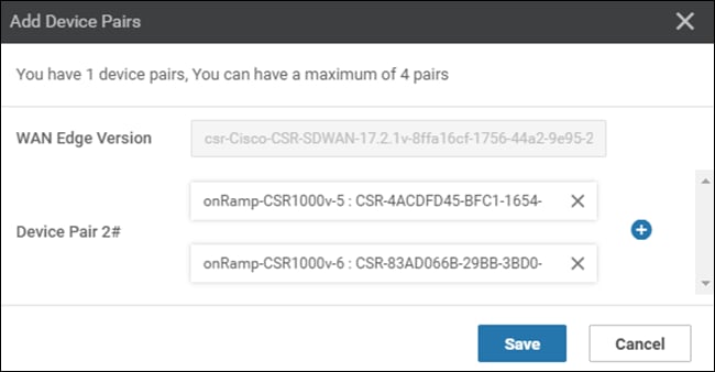
In order to add one or more additional device pairs, you must have previously attached device templates to the software tokens representing the Cisco SD-WAN Edge devices within vManage. Otherwise, you will get an error when you click on Add Device Pair from the drop-down menu.
The WAN Edge Version field will automatically be filled in for you. You can only add additional Cisco SD-WAN Edge devices which are of the same device type (Cisco CSR 1000v or Cisco vEdge Cloud) and the same OS version, to an existing transit VPC. You cannot mix and match Cisco CSR 1000v and vEdge Cloud devices within a single transit VPC; nor can you run different multiple Cisco CSR 1000v or vEdge Cloud device pairs, each with different OS versions, within a single transit VPC. You can click on the + icon to add additional device pairs, for a total of four device pairs per transit VPC.
Step 6. Click on the Save button to add the additional devices to the transit VPC and close the Add Device Pair pop-up window.
Adding device pairs to the transit VPC does not instantiate the Cisco SD-WAN Edge devices within the transit VPC. As shown in the figure below, the WAN edge State of the highlighted device pair does not show either a green “up” arrow, nor a red “down” arrow. This indicates that instances for the second device pair have not be instantiated within the transit VPC.
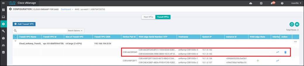
Additional device pairs are only instantiated when the Max. Host VPCs per Device Pair setting has been exceeded for the existing device pair(s) within the transit VPC.
Step 7. To change the maximum number of host VPCs per transit VPC device pair, click Edit Transit Details from the drop-down menu in Figure 45.
The Edit Transit VPC pop-up window will appear, as shown below.
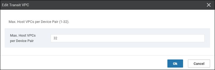
You can change the Max. Host VPCs per Device Pair setting from 1 to 32. When the number of host VPCs mapped to a given transit VPC is exceeded, the next time you add a host VPC to the transit VPC, a new device pair will be instantiated – if you have added one or more additional (currently unused) device pairs to the transit VPC.
Step 8. Change the maximum number of host VPCs per transit VPC device pair to meet your requirements and click OK to save the changes and close the Edit Transit VPC window.
| Tech tip |
| Editing the Max. Host VPCs per Device Pair setting on a transit VPC will not affect the number of host VPCs already mapped to a device pair within the transit VPC. For example, if you currently have two host VPCs mapped to a device pair within the transit VPC, and you decrease the Max. Host VPCs per Device Pair setting to 1, Cisco Cloud onRamp for IaaS will not automatically instantiate a new device pair and move the second host VPC to the new device pair. The current device pair will continue to function with both host VPCs mapped to it. Note also that decreasing the Max. Host VPCs per Device Pair to a number below the number of host VPCs already mapped to a transit VPC device pair is not recommended. Instead, consider un-mapping the host VPCs first, decreasing the Max Host VPCs per Device Pair setting, and then re-mapping the host VPCs (which will trigger the autoscaling feature). Of course, it is recommended you do this only do this during a scheduled maintenance window. |
Cisco Cloud onRamp for IaaS will not automatically scale down a device pair (Cisco CSR 1000v or vEdge Cloud routers) within a transit VPC if all host VPCs associated with the device pair are unmapped. In other words, Cisco Cloud onRamp for IaaS will not automatically un-instantiate (shut down) a device pair with no host VPCs attached within a transit VPC. However, you can manually trigger the autoscaling feature to achieve this.
Step 9. To manually trigger the autoscaling feature, click Trigger Autoscale from the drop-down menu in Figure 45.
This will bring up a pop-up window asking you to confirm that you want to trigger the autoscaling feature.
Step 10. Click OK to proceed.
The autoscaling feature will proceed to shut down any unused device pairs within the transit VPC. The device pair will still be available for scaling up, if the number of host VPCs mapped to the existing device pair(s) exceeds the Max. Host VPCs per Device Pair setting on a transit VPC.
Note also, that if the number of device pairs operating within the transit VPC is already optimized when you manually trigger the autoscaling feature, you will simply receive a notification of this, and no further actions will be taken.
Step 11. When you are done with the transit VPC you can delete it by selecting Delete Transit from the drop-down menu in Figure 45.
However, if you have host VPCs mapped to the transit VPC that you attempt to delete, Cisco Cloud onRamp for IaaS will display a warning, informing you that you must first un-map the host VPCs.
Step 12. In order to un-map host VPCs from the transit VPC, select the Host VPCs tab within the screen which displays additional details regarding the cloud instance, then select Mapped Host VNets.
An example is shown in the following figure.
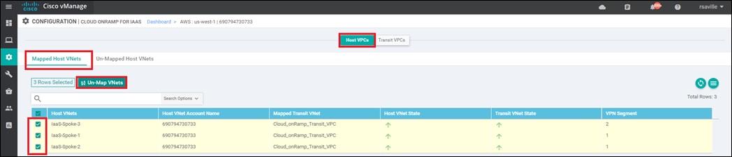
Step 13. Click the check boxes to the left of the host VPCs you wish to un-map and click the Un-Map VNets button.
Step 14. Click OK on the confirmation pop-up box which will appear.
The Task View screen will appear. After a few minutes the Status column should show Success. You can then go back to Step 11 and delete the transit VPC.
It should be noted that you cannot change any of the following once the transit VPC has been created:
● The name of the transit VPC
● The type of Cisco SD-WAN Edge devices (Cisco CSR 1000v or vEdge Cloud routers) deployed within the transit VPC
● The OS version deployed within the transit VPC
● The IPv4 CIDR block range deployed within the transit VPC
● The SSH key necessary for accessing the AWS EC2 instances upon which the Cisco SD-WAN Edge devices run, within the transit VPC
If do you need to change any of these parameters, all you can do is un-map the host VPCs, delete the transit VPC, and start all over again.
| Tech tip |
| The configuration deployed on the Cisco SD-WAN Edge routers within the transit VPC can be modified by making the appropriate changes to the template within Cisco vManage and deploying the changes to the devices. However, some caution needs to be taken, so as not to attempt to modify or over-write configuration pushed by Cisco Cloud onRamp for IaaS when mapping host VPCs to the transit VPC. Please refer to the Host VPC to Transit VPC Mapping section within the Design chapter of this deployment guide for details. |
Operate - Cisco Cloud onRamp for IaaS monitoring
Process: Monitor Cisco Cloud onRamp for IaaS
When you monitor Cisco Cloud onRamp for IaaS, you can view the following:
● The connectivity state of each host VPC
● The state of the transit VPC
● Detailed traffic statistics for the IPsec VPN connections between the transit VPC and each host VPC
Procedure 1. View the connectivity state of each host VPC
Step 1. Select the cloud icon at the top of the vManage GUI
Step 2. From the drop-down menu select Cloud OnRamp for IaaS.
Alternatively, to get to this page, you can select Configuration > Cloud onRamp for IaaS in the left-hand column of vManage.
You will come to a page displaying each configured cloud instance as a widget. Each widget will list how many host VPCs are mapped to any of the transit VPCs within the cloud instance, and how many transit VPCs are defined for the cloud instance. An example is shown in the following figure.
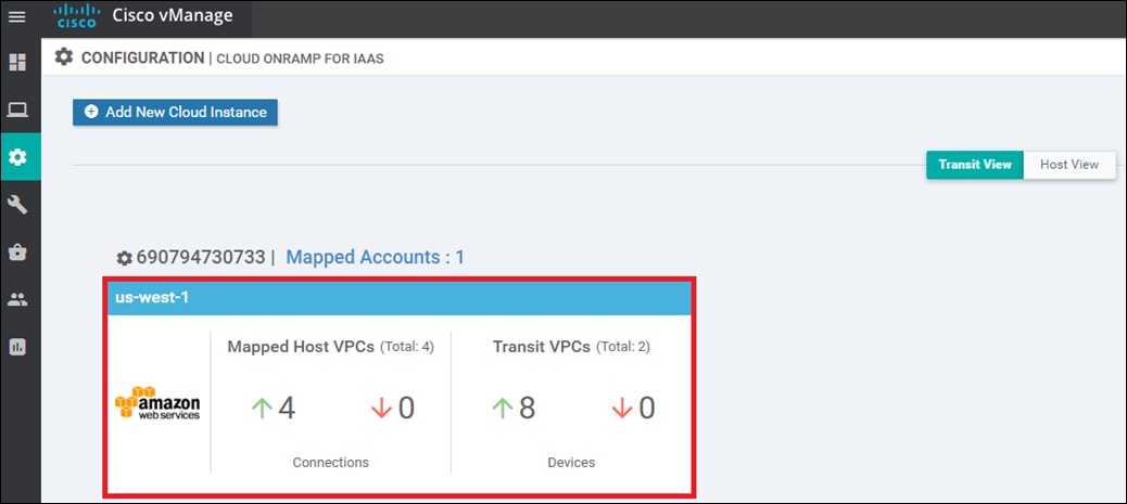
The aggregate number of host VPCs which are reachable is indicated with a green "up" arrow under Mapped Host VPCs. The aggregate number of host VPCs which are unreachable is indicated with a red "down" arrow. The color-coded "up" and "down" arrows indicates whether the IPsec VPN tunnels connecting the host VPC with the transit VPC are up or down.
The aggregate number of Cisco SD-WAN Edge routers which are reachable is indicated with a green "up" arrow under Transit VPCs. Likewise, the aggregate number of Cisco SD-WAN Edge routers which are unreachable is indicated with a red "down" arrow. In the case of transit VPCs, the color-coded "up" and "down" arrows indicate whether the logical Cisco SD-WAN Edge router is reachable or not. Generally, reachability indicates whether the Cisco SD-WAN Edge router is running or not. Note that there can be up to eight (4 pairs) of Cisco SD-WAN Edge routers per transit VPC.
Although the widget can be used to quickly display whether any of the Cisco SD-WAN Edge routers is down / unreachable, or whether any of the host VPCs is unreachable, it does not tell you which specific Cisco SD-WAN Edge router is down / unreachable, or which host VPC is unreachable. For this information you must look further within the cloud instance.
Step 3. Click on the cloud instance (area highlighted in red in the figure above).
When you click on the cloud instance, by default you are taken to a screen which displays the state of each host VPC within that cloud instance. An example is shown in the following figure.
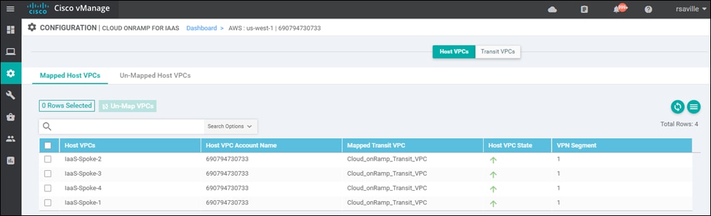
You can see specific details regarding whether individual host VPCs are up or down. You can also see which service VPN the host VPC is mapped to at the transit VPC.
Step 4. Click on the Transit VPCs tab
When you click on the Transit VPCs tab, you will be taken to a screen which displays the state of each transit VPC within the cloud instance. An example is shown in the following figure.
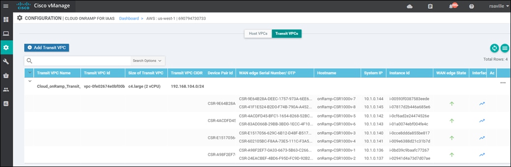
You can re-arrange the columns by dragging-and-dropping them so that the columns with the most relevant information come first, as shown in the figure above. You can see the state of each of the pairs of redundant Cisco SD-WAN Edge devices within the transit VPC. The state of each of the Cisco SD-WAN Edge routers within each transit VPC is displayed with a green "up" arrow or a red "down" arrow.
Procedure 2. View detailed traffic statistics for the IPsec VPN connections between the transit VPC and each host VPC
Although the more detailed information discussed in the previous procedure is useful in determining if a given Cisco SD-WAN Edge router is up or down, it doesn't provide any information regarding the traffic between the transit VPC and each host VPC.
Step 1. Click on the graph icon for one of the Cisco SD-WAN Edge routers under the Interface Stats column shown in the figure above.
A pop-up screen displaying statistics for the Tunnel interfaces between the Cisco SD-WAN Edge router and the host VPC(s) is displayed. An example is shown in the following figure.
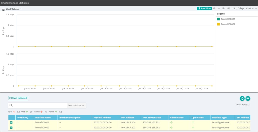
From the drop-down menu under Chart Options, you can select the information displayed within the graph over each collection interval. The options are as follows:
● Kbps - Traffic rate in kilobits per second for each collection interval
● Packets - Packets seen over each collection interval
● Octets - Bytes seen over each collection interval
● Errors - Number of errors over each collection interval
● Drops - Number of dropped packets over each collection interval
● Pps - Rate in packets per second over each collection interval
The collection interval displayed within the graph varies based upon overall length of time displayed within the graph. This is selected in the upper right corner of the pop-up window. The choices for overall length of time are as follows:
● Real Time - This results in a collection interval of 10 seconds displayed within the graphs.
● 1 Hour - This results in a collection interval of 10 minutes displayed within the graphs
● 3 Hours - This results in a collection interval of 10 minutes displayed within the graphs
● 6 Hours - This results in a collection interval of 10 minutes displayed within the graphs
● 12 Hours - This results in a collection interval of 30 minutes displayed within the graphs
● 24 Hours - This results in a collection interval of 30 minutes displayed within the graphs
● 7 Days - This results in a collection interval of 30 minutes displayed within the graphs
● Custom - This allows you to select a custom start date & time and end date & time. The collection interval depends on the start and end dates and times.
The collection interval is important because traffic rates may appear differently depending upon the interval over which they are averaged. Likewise, packet or byte counts will appear smaller over smaller collection intervals.
Statistics are displayed in both the transmit and receive direction - from the perspective of the Cisco SD-WAN Edge router logical Tunnel interfaces configured within the transit VPN. By default, statistics are displayed for all Tunnel interfaces. You can remove an interface from the graph by un-selecting it in the panel below the graph.
Step 2. When you are done viewing traffic statistics, close the pop-up window by clicking the "X" in the upper right corner.
This will take you back to the screen which displays the state of each transit VPC within the cloud instance.
Interconnecting Cisco SD-WAN with AWS Transit Gateway (TGW)
This section is intended for Cisco SD-WAN deployments not yet running vManage release 20.3, and/or for deployments with existing AWS Transit Gateways, and/or customers who wish to use only Cisco vEdge and vEdge Cloud routers within their SD-WAN deployments, that cannot leverage the benefits of the automation within Cisco Cloud onRamp for Multi-Cloud. The use of the Cisco Cloud onRamp for Multi-Cloud to deploy a Cisco SD-WAN Cloud Gateway design is recommended for customers with new (not yet existing) AWS Transit Gateway deployments and deployments with Cisco SD-WAN 20.3 and higher. Cisco Cloud onRamp for Multi-Cloud only supports the deployment of Cisco CSR 1000v routers within the AWS transit VPC.
This section covers the deployment of an AWS transit VPC and the connection of that transit VPC to an existing AWS Transit Gateway using VPN attachments – separate from the automation within Cisco Cloud onRamp for Multi-Cloud. It assumes host VPCs are already connected to the AWS Transit Gateway via VPC attachments. This section also assumes a transit VPC has already been provisioned with two Cisco SD-WAN Edge routers instantiated within the transit VPC. The method by which the transit VPC with Cisco SD-WAN Edge routers is created is outside the scope of this document, but could include one of the following:
● Manual configuration via the AWS web console
● Automation via AWS CloudFormation templates
● Automation via Python scripts and the AWS Boto3 API
● Automation via Ansible playbooks and the AWS Boto3 API
This section will use a transit VPC created by Cisco Cloud onRamp for IaaS as an example only - simply to show the additional configuration (BGP and Interface IPsec VPN feature templates) required to connect an existing AWS Transit Gateway to the transit VPC via Site-to-Site IPsec VPN connections. It is not recommended to use Cisco Cloud onRamp for IaaS to create a transit VPC (with or without attached host VPCs), and then manually attach an AWS Transit Gateway to the transit VPC. The reasons are discussed below.
Cisco Cloud onRamp for IaaS creates the equivalent configuration that would be found in a BGP feature template and two VPN Interface IPsec feature templates applied to each SD-WAN service VPN to which a host VPC is mapped, within the device templates attached each Cisco SD-WAN Edge router within the transit VPC. This is done as each host VPC is mapped to a service VPN within the transit VPC (not when the transit VPC is initially created). However, Cisco Cloud onRamp for IaaS does not create these additional feature templates as the host VPCs are mapped to the transit VPC. Instead the configuration is modified dynamically by Cisco Cloud onRamp for IaaS. Hence, it is possible for you to manually add BGP feature templates and VPN Interface IPsec templates after the transit VPC has been created and Cisco SD-WAN Edge routers have been instantiated by Cisco Cloud onRamp for IaaS.
When using Cisco Cloud onRamp for IaaS to create a transit VPC, you must exercise caution if you wish to modify the configuration of the Cisco SD-WAN Edge routers within a transit VPC after you have mapped host VPCs to it. If you add a BGP feature template to a service VPN interface within the device template for the Cisco SD-WAN Edge router, you must use BGP ASN 9988 in the feature template. This is the BGP ASN that Cisco Cloud onRamp for IaaS uses when mapping host VPCs to the transit VPC. Network devices can only be part of a single BGP ASN at one time. Likewise if you add IPsec VPN connections, you must make sure you don’t duplicate the Tunnel/ipsec interface numbers automatically generated by Cisco Cloud onRamp for IaaS when it mapped the host VPCs to the transit VPC using Site-to-Site IPsec VPN connections on the Cisco SD-WAN Edge router. Although it is possible to do both of these if you are very careful with the configuration – due to potential conflicts between the configuration automatically provisioned by Cisco Cloud onRamp for IaaS and your manual configuration, this is generally not recommended.
The high-level design for this section is shown in the following figure.
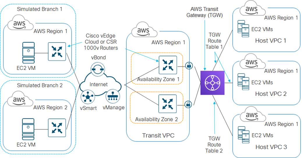
In the high-level design for this section, three existing host VPCs within the same region are connected to an AWS Transit Gateway through VPC attachments. The first two host VPCs are mapped to one route table within the AWS Transit Gateway, and the third host VPC is associated with a second route table within the AWS Transit Gateway. The Cisco SD-WAN Edge routers within the transit VPC are then connected to the AWS Transit Gateway to through VPN attachments (Site-to-Site IPsec VPN connections).
The creation of the AWS Transit Gateway and association of the host VPCs to the Transit Gateways is assumed to be completed already. This section will cover the manual configuration of the Site-to-Site VPN connections between the Cisco SD-WAN Edge routers within the transit VPC and the AWS Transit Gateway. The following use case is discussed.
Use case – segmentation to AWS using a Transit Gateway design
In this use case, host VPCs 1 and 2 (IaaS-Spoke-1 and IaaS-Spoke-2) are associated with the same route table (TGW_Route_Table_1) within the AWS Transit Gateway. Host VPC 3 (IaaS-Spoke-3) is associated with a different Transit Gateway route table (TGW_Route_Table_2). Routes from all host VPCs are propagated into the AWS Transit Gateway.
SD-WAN Service VPNs 1 and 2 within the transit VPC are both attached to the AWS Transit Gateway via VPN connections. Service VPN 1 is associated with Transit Gateway route table TGW_Route_Table_1. Service VPN 2 is associated with Transit Gateway route table TGW_Route_Table_2. Routes from both VPN attachments from the transit VPC are propagated into the AWS Transit Gateway.
Because host VPCs 1 and 2 (IaaS-Spoke-1 and IaaS-Spoke-2) and service VPN 1 are mapped to the same AWS Transit Gateway route table (TGW_Route_Table_1) and have routes propagated, communication is allowed between host VPCs 1 and 2 and with the Cisco SD-WAN through service VPN 1. Since host VPC 3 (IaaS-Spoke-3) and service VPN 2 are mapped to the same AWS Transit Gateway route table (TGW_Route_Table_2) and have routes propagated, communication is allowed between host VPC 3 and the Cisco SD-WAN through service VPN 2.
However, devices on service VPN 1 of the Cisco SD-WAN cannot communicate with applications running on EC2 instances within host VPC 3 (IaaS-Spoke-3). Likewise devices on service VPN 2 of the Cisco SD-WAN cannot communicate with applications running on EC2 instances within host VPCs 1 & 2 (IaaS-Spoke-1 and IaaS-Spoke-2). No communication is allowed between applications running on EC2 instances within host VPCs 1 & 2 (IaaS-Spoke-1 and IaaS-Spoke-2) and applications running on EC2 instances within host VPC 3 (IaaS-Spoke-3). Finally SD-WAN service VPN 1 cannot communicate with SD-WAN service VPN 2.
This demonstrates the use case where different entities within an organization require access only to specific public cloud resources. The figure below demonstrates this use case.
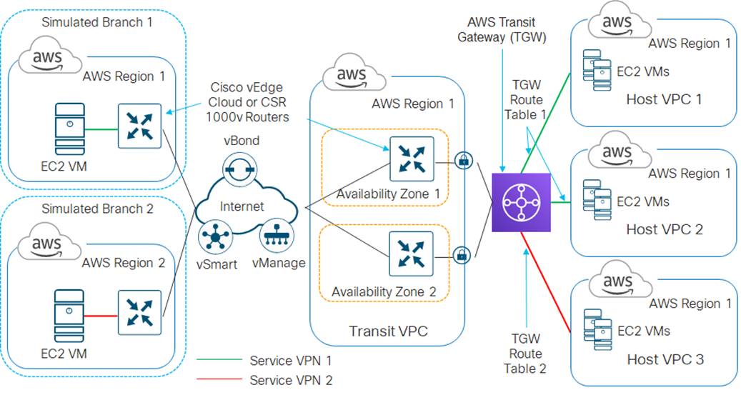
This following processes will discuss the manual connection of an AWS Transit Gateway (TGW) to a pair of Cisco CSR 1000v routers already instantiated and running within a transit VPC.
Process: Manually connecting Cisco CSR 1000v routers within a transit VPC to an AWS TGW
Procedure 1. Determine the AWS Elastic IP addresses associated with the VPN 0 (transport) interfaces of the CSR 1000v routers within the AWS transit VPC.
You will need to create two AWS Customer Gateways (CGWs) – one for each of the VPN 0 (transport) interfaces of the Cisco CSR 1000v routers within the transit VPC. The CGWs will reference the Elastic IP addresses assigned to these interfaces.
For this deployment guide, the VPN 0 (transport) interface of the Cisco CSR 1000v routers is GigabitEthernet2. Within AWS, interfaces on EC2 instances are referenced beginning with eth0 and counting up. For example eth0, eth1, etc. Since Cisco CSR 1000v routers begin with GigabitEthernet1, eth0 refers to GigabitEthernet1 and eth1 refers to GigabitEthernet2.
Step 1. Login to the AWS console at https://console.aws.amazon.com.
Step 2. Enter your AWS Account ID, IAM username, and Password.
Step 3. From the AWS console home page, select Services from the menu bar across the top of the screen to display the drop-down menu.
Step 4. From the drop-down menu, select EC2 under the Compute section.
This will bring up the EC2 Dashboard.
Step 5. In the navigation panel on the left side of the EC2 Dashboard, select Instances under Instances.
This will display the EC2 instances within the AWS region.
Step 6. Locate and select the first Cisco CSR 1000v router in the transit VPC, from the list of EC2 instances, to display details about the instance.
Step 7. Select the Description tab, and hover over the interface assigned to VPN 0 (transport interface) of the CSR 1000v (eth1 in this deployment guide) in the Network Interfaces section of the display.
The pop-up display will show the Elastic IP address associated with the interface of the CSR 1000v router. An example is shown in the figure below.
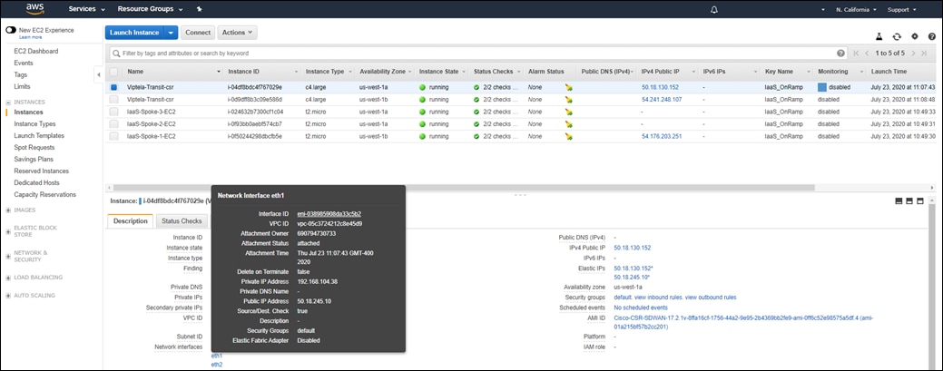
Step 8. Take note of the Elastic IP address, you will need this when creating the AGW Customer Gateways (CGWs) in the next procedure.
Step 9. Repeat Steps 6-8 for the second Cisco CSR 1000v router within the transit VPC.
For this deployment guide the Elastic IP addresses are as follows:
● Elastic IP address of the VPN 0 interface of the first Cisco CSR 1000v router: 50.18.245.10
● Elastic IP address of the VPN 0 interface of the second Cisco CSR 1000v router: 52.52.234.144
Procedure 2. Create AWS Customer Gateways for the VPN attachments to the Cisco CSR 1000v routers
Step 1. From within AWS, select Services from the menu bar across the top of the screen to display the drop-down menu.
Step 2. From the drop-down menu, select VPC under the Networking & Content Delivery section.
This will bring up the VPC Dashboard.
Step 3. In the navigation panel on the left side of the VPC Dashboard, select Customer Gateways under Virtual Private Networks (VPNs).
Step 4. In the screen which appears, click the Create Customer Gateway button.
A screen similar to the following will appear.
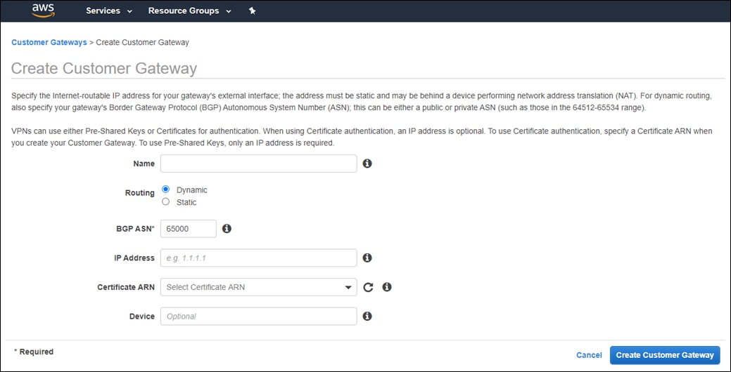
Step 5. Fill in the information for the screen and click the Create Customer Gateway button.
The following information was entered for the Customer Gateway (CGW) corresponding to the first CSR 1000v router within the transit VPC.
Name: Transit_VPC_CGW_1
Routing: Dynamic
BGP ASN: 65011
IP Address: 50.18.245.10
This is the Elastic IP address of the VPN 0 (transport) interface of the first Cisco CSR 1000v router within the transit VPC.
Certificate ARN: <Left Blank>
Device: <Left Blank>
Step 6. Repeat Steps 4 - 5 to create another Customer Gateway (CGW) for the second CSR 1000v router within the transit VPC.
The following information was entered for the Customer Gateway (CGW) corresponding to the second CSR 1000v router within the transit VPC.
Name: Transit_VPC_CGW_2
Routing: Dynamic
BGP ASN: 65011
IP Address: 50.18.234.50
This is the Elastic IP address of the VPN 0 (transport) interface of the second Cisco CSR 1000v router within the transit VPC.
Certificate ARN: <Left Blank>
Device: <Left Blank>
When you have completed this procedure, both Customer Gateways (CGWs) should appear as show in the following figure.
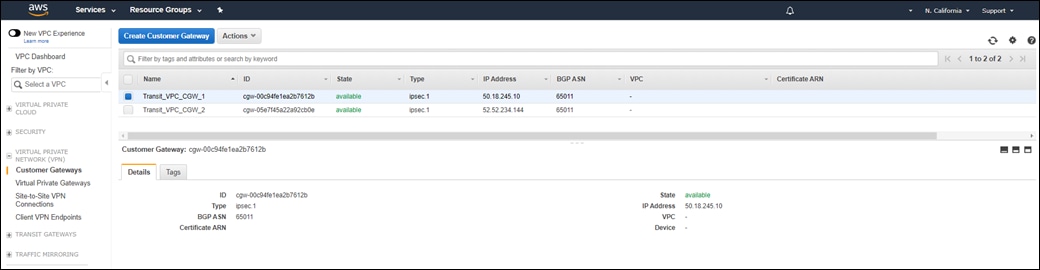
Procedure 3. Create Transit Gateway VPN attachments for the Cisco CSR 1000v routers within the transit VPC
In this procedure, for each SD-WAN service VPN mapped to the AWS Transit Gateway you will create a VPN attachment within the AWS Transit Gateway for each of the Cisco CSR 1000v routers within the transit VPC. By mapping each SD-WAN service VPN through a separate pair of AWS Transit Gateway VPN attachments, you can extend SD-WAN segmentation into the AWS Transit Gateway.
If you only desire to extend a single SD-WAN service VPN into the AWS Transit Gateway (perhaps only service VPN 1), then you only need a single set of AWS Transit Gateway VPN attachments for the two CSR 1000v routers within the transit VPC.
This section will demonstrate how to extend service VPNs 1 and 2 to the AWS Transit Gateway through VPN attachments. The IPsec VPN connections created as part of the VPN attachments will reference the Customer Gateways (CGWs) created in the previous procedure.
Step 1. From within AWS, select Services from the menu bar across the top of the screen to display the drop-down menu.
Step 2. From the drop-down menu, select VPC under the Networking & Content Delivery section.
This will bring up the VPC Dashboard.
Step 3. In the navigation panel on the left side of the VPC Dashboard, select Transit Gateway Attachments under Transit Gateways.
This will bring up a screen displaying existing transit gateway attachments and allow you to create new transit gateway attachments. An example is shown in the figure below.
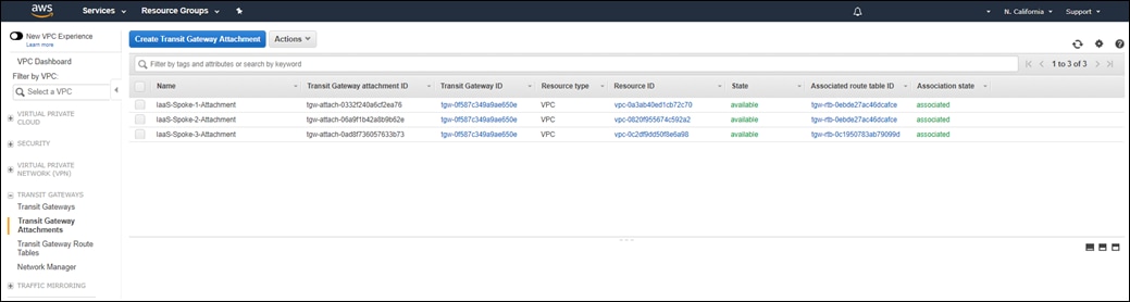
Host VPCs already attached to the Transit Gateway will appear with a Resource type of VPC, indicating a VPC attachment as opposed to a VPN attachment.
Step 4. Click the Create Transit Gateway Attachment button to bring up the screen to add a new Transit Gateway attachment.
An example of the screen is shown in the following figure.
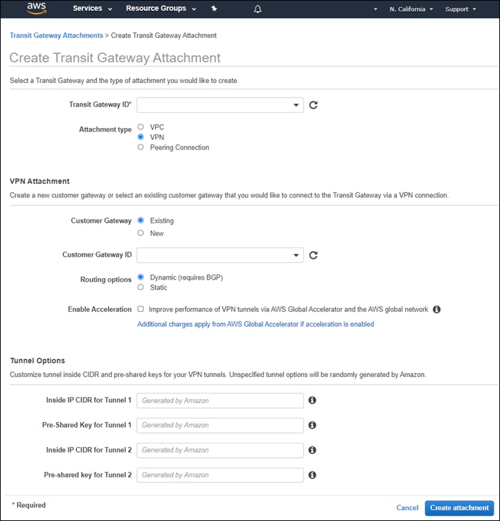
Step 5. Fill in the necessary information and click the Create attachment button.
The following information was entered for the Transit Gateway attachment corresponding to the first CSR 1000v router (onRamp-CSR1000v-1) within the transit VPC, to be used for SD-WAN service VPN 1.
Transit Gateway ID: tgw-0f587c349a9ae650e
From the drop-down menu adjacent to Transit Gateway ID, select the Transit Gateway to which you wish to attach the transit VPC. For this deployment guide only a single Transit Gateway exists, so there was only one option.
Attachment type: VPN
When you select VPN, the VPN Attachment fields will change, and Tunnel Options fields will appear.
VPN Attachment
Customer Gateway: Existing
Select Existing to use one of the Customer Gateways (CGWs) you created in the previous procedure.
Customer Gateway ID: cgw-00c94fe1ea2b7612b
From the drop-down menu adjacent to Customer Gateway ID, select the first Customer Gateway which you created based upon the Name tag – Transit_VPC_CGW_1 in the previous procedure.
Routing Options: Dynamic (requires BGP)
Enable Acceleration: Unchecked
Tunnel Options
Inside IP CIDR for Tunnel 1: 169.254.105.0/30
You can choose to have Amazon automatically generate the IP address CIDR for the Tunnel 1 and Tunnel 2 interfaces or you can manually configure it. If you choose to manually configure the CIDR block ranges for the tunnels they must be specified as /30 addresses within the 169.254.0.0/16 address block. Be sure not to overlap with any other Tunnel interfaces if you are using dynamic routing with BGP. When you specify a /30 CIDR block, there will only be two IP addresses for assignment to devices. AWS will automatically assign the lower address to the Tunnel interface on the AWS side of the IPsec tunnel. You must configure the higher address as the Tunnel interface on the Cisco CSR 1000v router within the transit VPC. For this deployment guide, the Tunnel IP address CIDR blocks were manually configured.
Pre-Shared Key for Tunnel 1: <Your Secret Key>
You can choose to have Amazon automatically generate the pre-shared keys for IKE for the Tunnel 1 and Tunnel 2 interfaces or you can manually configure it. For this deployment guide the pre-shared keys were manually configured.
Inside IP CIDR for Tunnel 2: 169.254.105.4/30
Pre-Shared Key for Tunnel 2: <Your Secret Key>
You will receive a confirmation that the creation of the VPN attachment was successful.
Step 6. Click Close to close the confirmation and return to the Transit Gateway Attachments screen.
It may take several minutes for the state of the new transit gateway attachment to transition from pending to available.
Step 7. Locate the new transit gateway attachment and click the pencil icon that appears when you hover over the left part of the Name field as shown in the figure below.
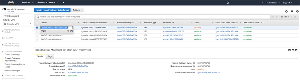
Step 8. In the Name field type in a name for the transit gateway attachment, so you can recognize it easier, and click the check mark icon below the Name field.
For this deployment guide, the first transit VPC attachment for SD-WAN service VPN 1 is named Transit-VPC-CSR1000v-1-VPN1.
Each SD-WAN service VPN which is mapped to the AWS Transit Gateway will require two VPN attachments, since there are two Cisco CSR 1000v routers within each transit VPC. The name of the first set of attachments reflects that these attachments are for the service VPN 1 extension into the AWS Transit Gateway. Note that the Name tag is the only thing that differentiates that the use of this AWS Transit Gateway VPN attachment is for SD-WAN service VPN 1.
Step 9. Select Site-to-Site VPN Connections under Virtual Private Network (VPN) from the navigation panel on the left side of the VPC Dashboard.
This will display the AWS Site-to-Site VPN Connection which was automatically created when you configured the Transit Gateway Attachment for the first CSR 1000v router (onRamp-CSR1000v-1) within the transit VPC.
Step 10. Select the Site-to-Site VPN Connection that was automatically created when you attached the transit VPC to the Transit Gateway, hover over the right-side of the Name field until the Pencil icon appears and click on it.
This will bring up a field for you to add a Name tag to the Site-to-Site VPN connection.
Step 11. Configure the Name tag for the Site-to-Site VPN connection corresponding to SD-WAN service VPN 1 on the first CSR 1000v router (onRamp-CSR1000v-1) as CSR-1000v-1_Service_VPN_1 and click the check mark adjacent to the Name field to save the tag.
An example is shown in the figure below.
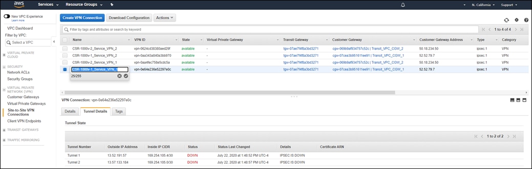
This will help you when you fill in the variables within the VPN IPsec Interface template applied to the Cisco CSR 1000v routers within the transit VPC in vManage.
Step 12. Copy the VPN Connection Name, Tunnel Number, Outside IP Address, and Inside IP CIDR for the Site-to-Site VPN connection.
You will need this information when you configure the VPN Interface IPsec feature templates within vManage to complete the IPsec VPN configuration on the Cisco CSR 1000v routers within the transit VPC. You will put this information in Table 5 below.
Step 13. Repeat Steps 4 – 12 for the second transit gateway attachment for the customer gateway corresponding to the second Cisco CSR 1000v router (onRamp-CSR1000v-2) within the transit VPC, for SD-WAN service VPN 1.
The following information was entered for the AWS Transit Gateway VPN attachment corresponding to the second CSR 1000v router (onRamp-CSR1000v-2) within the transit VPC, for SD-WAN service VPN 1.
Transit Gateway ID: tgw-0f587c349a9ae650e
Attachment type: VPN
When you select VPN, the VPN Attachment fields will change, and Tunnel Options fields will appear.
VPN Attachment
Customer Gateway: Existing
Customer Gateway ID: cgw-05e7f45a22a92cb0e
From the drop-down menu adjacent to Customer Gateway ID, select the second Customer Gateway which you created based upon the Name tag – Transit_VPC_CGW_2 in the previous procedure.
Routing Options: Dynamic (requires BGP)
Enable Acceleration: Unchecked
Tunnel Options
Inside IP CIDR for Tunnel 1: 169.254.105.8/30
Pre-Shared Key for Tunnel 1: <Your Secret Key>
Inside IP CIDR for Tunnel 2: 169.254.105.12/30
Pre-Shared Key for Tunnel 2: <Your Secret Key>
The Name tag associated with the Site-to-Site VPN connection corresponding to SD-WAN service VPN 1 on the second Cisco CSR 1000v router (onRamp-CSR1000v-2) within the transit VPC is CSR-1000v-2 Service_VPN_1.
Step 14. (Optional) For each additional service VPN which will be mapped to the AWS Transit Gateway, create two additional VPN attachments. Additional VPN attachments will use the same pair of AWS customer gateways corresponding to the VPN 0 interfaces of the same set of Cisco CSR 1000v routers within the transit VPC. Only the IP CIDR address ranges for the Tunnel interfaces, and optionally the pre-shared keys for each Tunnel interface, are different from the first set of VPN attachments.
For this deployment guide, the first transit VPC attachment for SD-WAN service VPN 2 is named Transit-VPC-CSR1000v-1-VPN2, and the second transit VPC attachment for SD-WAN service VPN 2 is named Transit-VPC-CSR1000v-2-VPN2, reflecting that these attachments are for service VPN 2.
The following information was entered for the Transit Gateway attachment corresponding to the first Cisco CSR 1000v router (onRamp-CSR1000v-1) within the transit VPC, to be used for SD-WAN service VPN 2.
Transit Gateway ID: tgw-0f587c349a9ae650e
Attachment type: VPN
VPN Attachment
Customer Gateway: Existing
Customer Gateway ID: cgw-00c94fe1ea2b7612b
Routing Options: Dynamic (requires BGP)
Enable Acceleration: Unchecked
Tunnel Options
Inside IP CIDR for Tunnel 1: 169.254.105.16/30
Pre-Shared Key for Tunnel 1: <Your Secret Key>
Inside IP CIDR for Tunnel 2: 169.254.105.20/30
Pre-Shared Key for Tunnel 2: <Your Secret Key>
The Name tag associated with the Site-to-Site VPN connection corresponding to SD-WAN service VPN 2 on the first Cisco CSR 1000v router (onRamp-CSR1000v-1) within the transit VPC is CSR-1000v-1_Service_VPN_2.
The following information was entered for the Transit Gateway attachment corresponding to the second Cisco CSR 1000v router (onRamp-CSR1000v-2) within the transit VPC, to be used for SD-WAN service VPN 2.
Transit Gateway ID: tgw-0f587c349a9ae650e
Attachment type: VPN
VPN Attachment
Customer Gateway: Existing
Customer Gateway ID: cgw-05e7f45a22a92cb0e
Routing Options: Dynamic (requires BGP)
Enable Acceleration: Unchecked
Tunnel Options
Inside IP CIDR for Tunnel 1: 169.254.105.24/30
Pre-Shared Key for Tunnel 1: <Your Secret Key>
Inside IP CIDR for Tunnel 2: 169.254.105.28/30
Pre-Shared Key for Tunnel 2: <Your Secret Key>
The Name tag associated with the Site-to-Site VPN connection corresponding to SD-WAN service VPN 2 on the second Cisco CSR 10000v router (onRamp-CSR1000v-2) within the transit VPC is CSR-1000v-2 Service_VPN_2.
For this deployment guide, the first transit VPC attachment for SD-WAN service VPN 2 is named Transit-VPC-CSR1000v-1-VPN2, and the second transit VPC attachment for SD-WAN service VPN 2 is named Transit-VPC-CSR1000v-2-VPN2. Again, each SD-WAN service VPN which is mapped to the AWS Transit Gateway will require two VPN attachments, since there are two Cisco CSR 1000v routers within each transit VPC. The name of the second set of attachments reflects that these attachments are for SD-WAN service VPN 2 extension into the AWS Transit Gateway. Note again that the Name tag is the only thing that differentiates the use of this AWS Transit Gateway VPN attachment is for SD-WAN service VPN 2.
The following is the information recorded for each of the AWS Transit Gateway VPN attachments from both Cisco CSR 1000v routers within the transit VPC and both service VPNs 1 & 2, along with the resulting Site-to-Site VPN connections created.
Table 5. AWS Transit Gateway VPN Attachments and Site-to-Site VPN Configuration values
| Transit Gateway Attachment Name |
Site-to-Site VPN Connection Name |
Tunnel Number |
Outside IP Address |
Inside IP CIDR |
| Transit-VPC-CSR1000v-1-VPN1 |
CSR-1000v-1_Service_VPN_1 |
Tunnel1 |
13.52.203.251 |
169.254.105.4/30 |
|
|
|
Tunnel2 |
54.153.28.22 |
169.254.105.0/30 |
| Transit-VPC-CSR1000v-2-VPN1 |
CSR-1000v-2_Service_VPN_1 |
Tunnel1 |
13.52.209.255 |
169.254.105.12/30 |
|
|
|
Tunnel2 |
54.183.184.98 |
169.254.105.8/30 |
| Transit-VPC-CSR1000v-1-VPN2 |
CSR-1000v-1_Service_VPN_2 |
Tunnel1 |
13.56.106.122 |
169.254.105.20/30 |
|
|
|
Tunnel2 |
52.8.127.146 |
169.254.105.16/30 |
| Transit-VPC-CSR1000v-2-VPN2 |
CSR-1000v-2_Service_VPN_2 |
Tunnel1 |
52.8.100.188 |
169.254.105.24/30 |
|
|
|
Tunnel2 |
52.9.122.137 |
169.254.105.28/30 |
| Tech tip |
| When creating AWS Transit Gateway VPN connections, always use the results from the AWS Site-to-Site VPN connections (not the Create Transit Gateway Attachment screen) to determine which Inside IP CIDR was actually associated with Tunnel1 versus Tunnel2. |
Note that when you are done adding the Transit Gateway VPN attachments, all IPsec tunnels within AWS will have a Status of DOWN, since you have not yet configured the IPsec connections on the Cisco CSR 1000v routers within the transit VPC. This will be done using feature templates added to the device templates of the Cisco CSR 1000v routers within vManage in an upcoming procedure.
Procedure 4. Move the transit VPC VPN attachments to the correct route tables within the Transit Gateway.
Step 1. In the navigation panel on the left side of the VPC Dashboard, select Transit Gateway Route Tables under Transit Gateways.
This will bring up a screen displaying existing Transit Gateway route tables. By default all Transit Gateway attachments are associated with the default route table of the Transit Gateway.
This deployment guide assumes that two additional Transit Gateway route tables – TGW_Route_Table_1 and TGW_Route_Table_2 have already been created. Further, the first two host VPCs (IaaS-Spoke-1 and IaaS-Spoke-2) are mapped to TGW_Route_Table_1; and the third host VPC (IaaS-Spoke-3) is associated to TGW_Route_Table_2. Routes from the first two host VPCs (IaaS-Spoke-1 and IaaS-Spoke-2) are propagated into TGW_Route_Table_1. Routes from the third host VPC (IaaS-Spoke-3) are propagated into TGW_Route_Table_2. This configuration of Transit Gateway route tables and route propagation allows communication between the first two host VPCs (IaaS-Spoke-1 and IaaS-Spoke-2), but not to the third host VPC (IaaS-Spoke-3).
When you created the Transit Gateway VPN attachments for service VPNs 1 and 2 on the two Cisco CSR 1000v routers within the transit VPC, the VPN attachments were put into the default route table of the Transit Gateway. For this use case, you must move the VPN attachments corresponding to service VPN 1 to TGW_Route_Table_1 and allow route propagation from the transit VPC into the Transit Gateway. Likewise, you must move the VPN attachments corresponding to service VPN 2 to TGW_Route_Table_2 and allow route propagation from the transit VPC into the Transit Gateway.
Step 2. Select the default route table within the Transit Gateway, and click on the Associations tab.
This will display the Transit Gateway attachments associated with the default route table. An example is shown in the following figure.
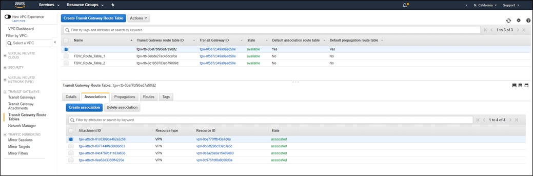
Step 3. Individually, select each of the Transit Gateway VPN attachments corresponding to the Cisco CSR 1000v routers within the transit VPC and click on the Delete association button.
Transit VGW attachments can only be associated to a single Transit Gateway route table at a time. Attachments must be un-associated before they can be re-associated to another route table.
Step 4. Click on the Propagations tab.
Step 5. Select each of the Transit Gateway VPN attachments corresponding to the Cisco CSR 1000v routers within the transit VPC and click on the Delete propagation button.
This should delete all the route propagations from the attachments of the Cisco CSR 1000v into the default route table as well.
Step 6. Select TGW_Route_Table_1, and click on the Associations tab.
You should see the attachments for the first two host VPCs already if they have been attached.
Step 7. Click the Create Association button.
The Create association screen will appear allowing you to select the Transit Gateway attachment which you wish to associate to the route table. An example is shown in the following figure.
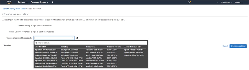
Step 8. Select the attachment corresponding to service VPN 1 of the first Cisco CSR 1000v router within the transit VPC (Transit-VPC-CSR1000v-1-VPN1) and click Create association.
Step 9. Click Close to close the confirmation which will appear.
Step 10. Repeat Steps 7 – 9 for the attachment corresponding to service VPN 1 of the second Cisco CSR 1000v router within the transit VPC (Transit-VPC-CSR1000v-2-VPN1).
Step 11. Click on the Propagations tab.
Step 12. Click the Create Propagation button.
The Create propagation screen will appear allowing you to select the Transit Gateway attachment which you wish to propagate routes into the route table. An example is shown in the following figure.
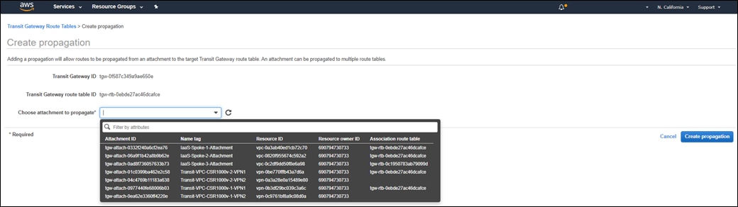
Step 13. Select the attachment corresponding to service VPN 1 of the first Cisco CSR 1000v router within the transit VPC (Transit-VPC-CSR1000v-1-VPN1) and click Create propagation.
Step 14. Click Close to close the confirmation which will appear.
Step 15. Repeat Steps 13 -14 for the attachment corresponding to service VPN 1 of the second Cisco CSR 1000v router within the transit VPC (Transit-VPC-CSR1000v-2-VPN1).
Step 16. Repeat Steps 6 – 15 to associate the attachments corresponding to service VPN 2 of the two CSR 1000v routers within the transit VPC (Transit-VPC-CSR1000v-1-VPN2 and Transit-VPC-CSR1000v-2-VPN2) to TGW_Route_Table_2 and propagate the routes from VPN 2 into the route table.
Procedure 5. Create additional feature templates for the Cisco CSR 1000v routers within the transit VPC
This procedure creates three new feature templates within vManage, which will then be added to the device templates attached to the Cisco CSR 1000v routers within the transit VPC. The new feature templates consist of the following:
● Two Cisco VPN Interface IPsec feature templates – one for each of the two IPsec VPN tunnels which will be created for each Cisco CSR 1000v router to connect to the AWS Transit Gateway for each service VPN mapped to the AWS Transit Gateway.
● One Cisco BGP template to be applied to each service VPN mapped to the AWS Transit Gateway.
Step 1. Create two new Cisco VPN Interface IPsec feature templates with values and variables as shown in the tables below.
IOS XE SD-WAN VPN Interface1 IPsec feature template
Devices: CSR1000v
Template: Cisco VPN Interface IPsec
Template Name: saville-IOS-XE_AWS_Transit_Interface1_IPsec
Description: IOS XE SD-WAN VPN Interface1 IPsec template for AWS Transit VPC CSR 1000v routers
Table 6. Cisco VPN Interface1 IPsec feature template settings
| Section |
Parameter |
Type |
Variable/Value |
| Basic Configuration |
Shutdown |
Global |
No |
|
|
Interface Name (1..255) |
Device Specific |
IPsec_tunnel1_if_name |
|
|
IPv4 Address |
Device Specific |
IPsec_tunnel1_ipv4_address |
|
|
Source |
Radio Button |
Interface |
|
|
IPsec Source IP Address |
Device Specific |
IPsec_tunnel1_source_interface |
|
|
IPsec Destination IP Address/FQDN |
Device Specific |
IPsec_tunnel1_destination |
|
|
TCP MSS |
Global |
1436 |
|
|
IP MTU |
Global |
1476 |
| IKE |
IKE Version |
Global |
2 |
|
|
IKE Rekey Interval (seconds) |
Global |
28800 |
|
|
IKE Cipher Suite |
Global |
AES 256 CBC SHA2 |
|
|
IKE Authentication > Preshared Key |
Device Specific |
IPsec_tunnel1_pre_shared_secret |
|
|
IKE Authentication > IKE ID for remote End point |
Device Specific |
IPsec_tunnel1_ike_remote_id |
|
|
IPsec Replay Window |
Global |
1024 |
|
|
IPsec Cipher Suite |
Global |
AES 256 CBC SHA 256 |
IOS XE SD-WAN VPN Interface2 IPsec feature template
Devices: CSR1000v
Template: Cisco VPN Interface IPsec
Template Name: saville-IOS-XE_AWS_Transit_Interface2_IPsec
Description: IOS XE SD-WAN VPN Interface2 IPsec template for AWS Transit VPC CSR 1000v routers
Table 7. Cisco VPN Interface2 IPsec feature template settings
| Section |
Parameter |
Type |
Variable/Value |
| Basic Configuration |
Shutdown |
Global |
No |
|
|
Interface Name (1..255) |
Device Specific |
IPsec_tunnel2_if_name |
|
|
IPv4 Address |
Device Specific |
IPsec_tunnel2_ipv4_address |
|
|
Source |
Radio Button |
Interface |
|
|
IPsec Source IP Address |
Device Specific |
IPsec_tunnel2_source_interface |
|
|
IPsec Destination IP Address/FQDN |
Device Specific |
IPsec_tunnel2_destination |
|
|
TCP MSS |
Global |
1436 |
|
|
IP MTU |
Global |
1476 |
| IKE |
IKE Version |
Global |
2 |
|
|
IKE Rekey Interval (seconds) |
Global |
28800 |
|
|
IKE Cipher Suite |
Global |
AES 256 CBC SHA2 |
|
|
IKE Authentication > Preshared Key |
Device Specific |
IPsec_tunnel2_pre_shared_secret |
|
|
IKE Authentication > IKE ID for remote End point |
Device Specific |
IPsec_tunnel2_ike_remote_id |
|
|
IPsec Replay Window |
Global |
1024 |
|
|
IPsec Cipher Suite |
Global |
AES 256 CBC SHA 256 |
Step 2. Create one new Cisco BGP feature template with values and variables as shown in the tables below.
IOS XE SD-WAN BGP feature template
Devices: CSR1000v
Template: Cisco BGP
Template Name: saville-IOS-XE_AWS_Transit_BGP
Description: IOS XE SD-WAN BGP template for AWS Transit VPC CSR 1000v routers
Table 8. Cisco BGP feature template settings
| Section |
Parameter |
Type |
Variable/Value |
| Basic Configuration |
Shutdown |
Global |
No |
|
|
AS Number |
Device Specific |
transit_vpc_bgp_as_num |
| Unicast Address Family |
Maximum Paths |
Global |
4 |
|
|
Redistribute > Protocol |
Global |
omp, connected |
| Neighbor (First New BGP Neighbor) |
Address |
Device Specific |
bgp_neighbor1_address |
|
|
Remote AS |
Device Specific |
bgp_neighbor1_remote_as |
|
|
Address Family (Radio Button) |
Global |
On |
|
|
Address Family |
Global |
ipv4-unicast |
| Neighbor (Second New BGP Neighbor) |
Address |
Device Specific |
bgp_neighbor2_address |
|
|
Remote AS |
Device Specific |
bgp_neighbor2_remote_as |
|
|
Address Family (Radio Button) |
Global |
On |
|
|
Address Family |
Global |
ipv4-unicast |
For the templates above, all values not specified within the tables are default values as of the vManage release 20.1.1.
Procedure 6. Modify the device templates of the Cisco CSR 1000v routers within the transit VPC to connect to the AWS Transit Gateway
In this procedure a Cisco BGP feature template and two Cisco VPN Interface IPsec templates are added as sub-templates to the service VPN (Cisco VPN) templates for each of the SD-WAN service VPNs which are to be extended to the AWS Transit Gateway.
For this section of the deployment guide, both SD-WAN service VPNs (VPN 1 & VPN 2) are extended to the AWS Transit Gateway.
Step 1. From the navigation panel on the left side of the vManage web-based interface select Configuration > Templates.
Step 2. Select the Device tab to display the device templates configured within vManage.
Step 3. Highlight the device template assigned to the Cisco CSR 1000v routers running in the transit VPC.
For this deployment guide, the device template for the Cisco CSR 1000v routers running within the transit VPC is saville-CSR1000v_Cloud_OnRamp_Transit_VPC.
Step 4. Click the … icon to the right of the device template to display the drop-down menu and select Edit.
An example is shown in the following figure.
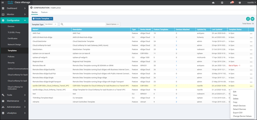
This will bring up the feature templates which are part of the device template.
Step 5. Scroll down to the Service VPN section.
For each SD-WAN service VPN extended to the transit VPC, there will be a Cisco VPN template corresponding to the VPN number (VPN 1, VPN 2, etc.). An example is shown in the following figure.
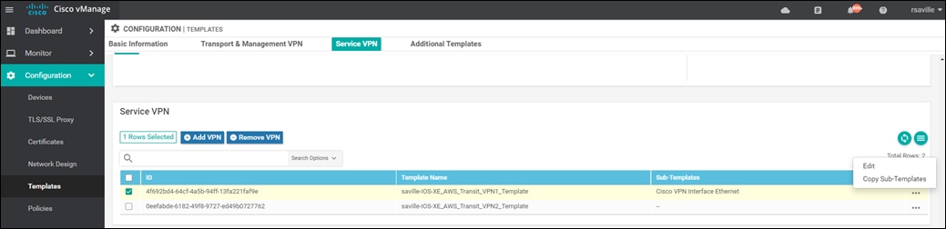
Step 6. Select the ID corresponding to service VPN 1, based on the Template Name.
Step 7. Click the … icon to the right of the service VPN template to display the drop-down menu and select Edit.
This will bring up a side-panel, allowing you to add sub-templates to the Cisco VPN template corresponding to service VPN 1.
Step 8. From the selection of Additional Cisco VPN Templates in right-side of the side-panel, click the + icon next to Cisco BGP to add a Cisco BGP sub-template to service VPN 1.
Step 9. From the drop-down menu adjacent to Cisco BGP, select the name of the Cisco BGP template you configured in the previous procedure - saville-IOS-XE_AWS_Transit_BGP.
Step 10. From the selection of Additional Cisco VPN Templates in the right-side of the side-panel, click the + icon next to Cisco VPN Interface IPsec twice in order to add two Cisco VPN Interface IPsec sub-templates to service VPN 1.
Step 11. From the drop-down menu adjacent to the first Cisco VPN Interface IPsec entry, select the name of the first Cisco VPN Interface IPsec template you configured in the previous procedure - saville-IOS-XE_AWS_Transit_Interface_IPsec_1.
Step 12. From the drop-down menu adjacent to the second Cisco VPN Interface IPsec entry, select the name of the second Cisco VPN Interface IPsec template you configured in the previous procedure - saville-IOS-XE_AWS_Transit_Interface_IPsec_2.
An example is shown in the following figure.
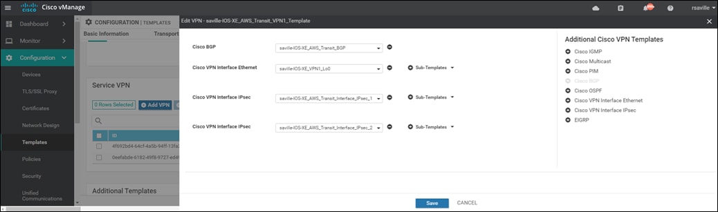
Step 13. Click Save to add these sub-templates to the Cisco VPN template corresponding to service VPN 1.
Step 14. Repeat Steps 6 – 13 for the VPN template corresponding to service VPN 2, selecting the same templates.
When you have finished updating the VPN template for service VPN 2 you will be taken back to the device template.
Step 15. Click Update to update the device template.
A new screen will appear, listing the two Cisco CSR 1000v routers within the transit VPC to which the device template has already been applied. An example is shown in the following figure.
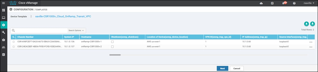
Step 16. Find the first Cisco CSR 1000v router (onRamp-CSR1000v-1), select … to the far right of it, and from the drop-down menu select Edit Device Template.
A pop-up screen will appear with a list of variables and empty text boxes. Most of the variables will be filled since the CSR 1000v router is already running within a transit VPC. Only new variables within the Cisco BGP and Cisco VPN Interface IPsec templates which were added to the device template will be blank. An example is shown in the figure below.
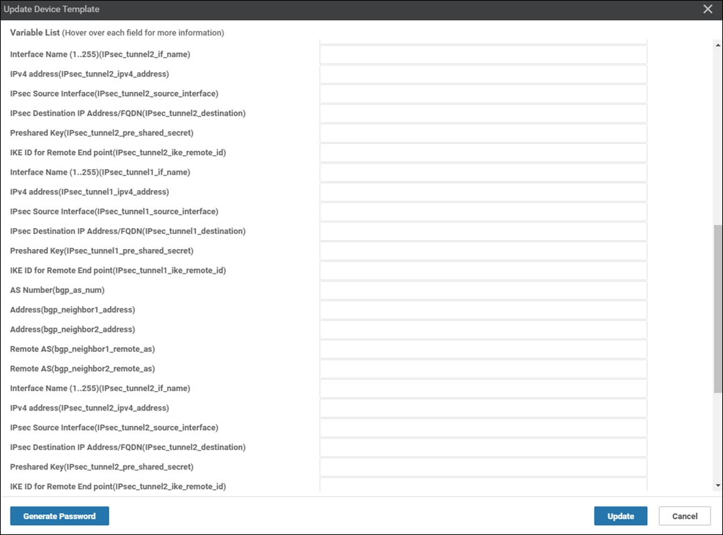
Filling in the additional device variables via the pop-up window is not ideal, because the variable names do not reflect which service VPN to which they belong. Therefore, the method shown here is to download the variables file as a .csv file and edit it through a program such as Microsoft Excel. The .csv file shows the full variable names which includes the service VPN to which the variable applies.
Step 17. Click Cancel to close the pop-up variables screen.
Step 18. Click the green down arrow in the upper right corner of the screen which displays the two Cisco CSR 1000v routers to which the template is being updated (Figure 56 above.).
This will download the variables file as a .csv file to your PC. The default name for the file is Template.csv.
Step 19. Locate the Template.csv file and double click on it to open it.
Step 20. Expand the column width of all the columns to fit the data by selecting all data (CTRL-A) and navigating to Format > AutoFit Column Width.
From the .csv file you will see the full variable name. Examples are as follows:
/1/IPsec_tunnel2_if_name/interface/ip/address
This references the inside IP address of the second Tunnel interface for service VPN 1 since the variable begins with /1.
/2//router/bgp/neighbor/bgp_neighbor1_address/remote-as
This references the BGP AS number of the peer connected to Tunnel 1 of service VPN 2 since the variable begins with /2.
Step 21. Fill in all the variables using the data you collected from when you configured the AWS Transit Gateway VPN attachments for the two Cisco CSR 1000v routers within the transit VPC (Table 5 above).
The following tables show the variables used when deploying the Cisco CSR 1000v routers for this deployment guide.
Table 9. onRamp-CSR1000v-1 additional device template variable values
| Variable |
Value |
| //IPsec_tunnel2_if_name/interface/if-name |
ipsec4 |
| /2/IPsec_tunnel2_if_name/interface/ip/address |
169.254.105.18/30 |
| /2/IPsec_tunnel2_if_name/interface/tunnel-source-interface |
GigabitEthernet2 |
| /2/IPsec_tunnel2_if_name/interface/tunnel-destination |
52.8.127.146 |
| /2/IPsec_tunnel2_if_name/interface/ike/authentication-type/pre-shared-key/pre-shared-secret |
<Your Secret Key> |
| /2/IPsec_tunnel2_if_name/interface/ike/authentication-type/pre-shared-key/ike-remote-id |
52.8.127.146 |
| /2/IPsec_tunnel1_if_name/interface/if-name |
ipsec3 |
| /2/IPsec_tunnel1_if_name/interface/ip/address |
169.254.105.22/30 |
| /2/IPsec_tunnel1_if_name/interface/tunnel-source-interface |
GigabitEthernet2 |
| /2/IPsec_tunnel1_if_name/interface/tunnel-destination |
13.56.106.122 |
| /2/IPsec_tunnel1_if_name/interface/ike/authentication-type/pre-shared-key/pre-shared-secret |
<Your Secret Key> |
| /2/IPsec_tunnel1_if_name/interface/ike/authentication-type/pre-shared-key/ike-remote-id |
13.56.106.122 |
| /2//router/bgp/as-num |
65011 |
| /2//router/bgp/neighbor/bgp_neighbor1_address/address |
169.254.105.21 |
| /2//router/bgp/neighbor/bgp_neighbor2_address/address |
169.254.105.17 |
| /2//router/bgp/neighbor/bgp_neighbor1_address/remote-as |
65010 |
| /2//router/bgp/neighbor/bgp_neighbor2_address/remote-as |
65010 |
| /1/IPsec_tunnel2_if_name/interface/if-name |
ipsec2 |
| /1/IPsec_tunnel2_if_name/interface/ip/address |
169.254.105.2/30 |
| /1/IPsec_tunnel2_if_name/interface/tunnel-source-interface |
GigabitEthernet2 |
| /1/IPsec_tunnel2_if_name/interface/tunnel-destination |
54.153.28.22 |
| /1/IPsec_tunnel2_if_name/interface/ike/authentication-type/pre-shared-key/pre-shared-secret |
<Your Secret Key> |
| /1/IPsec_tunnel2_if_name/interface/ike/authentication-type/pre-shared-key/ike-remote-id |
54.153.28.22 |
| /1/IPsec_tunnel1_if_name/interface/if-name |
ipsec1 |
| /1/IPsec_tunnel1_if_name/interface/ip/address |
169.254.105.6/30 |
| /1/IPsec_tunnel1_if_name/interface/tunnel-source-interface |
GigabitEthernet2 |
| /1/IPsec_tunnel1_if_name/interface/tunnel-destination |
13.52.203.251 |
| /1/IPsec_tunnel1_if_name/interface/ike/authentication-type/pre-shared-key/pre-shared-secret |
<Your Secret Key> |
| /1/IPsec_tunnel1_if_name/interface/ike/authentication-type/pre-shared-key/ike-remote-id |
13.52.203.251 |
| /1//router/bgp/as-num |
65011 |
| /1//router/bgp/neighbor/bgp_neighbor1_address/address |
169.254.105.5 |
| /1//router/bgp/neighbor/bgp_neighbor2_address/address |
169.254.105.1 |
| /1//router/bgp/neighbor/bgp_neighbor1_address/remote-as |
65010 |
| /1//router/bgp/neighbor/bgp_neighbor2_address/remote-as |
65010 |
Table 10. onRamp-CSR1000v-2 additional device template variable values
| Variable |
Value |
| //IPsec_tunnel2_if_name/interface/if-name |
ipsec4 |
| /2/IPsec_tunnel2_if_name/interface/ip/address |
169.254.105.30/30 |
| /2/IPsec_tunnel2_if_name/interface/tunnel-source-interface |
GigabitEthernet2 |
| /2/IPsec_tunnel2_if_name/interface/tunnel-destination |
52.9.122.137 |
| /2/IPsec_tunnel2_if_name/interface/ike/authentication-type/pre-shared-key/pre-shared-secret |
<Your Secret Key> |
| /2/IPsec_tunnel2_if_name/interface/ike/authentication-type/pre-shared-key/ike-remote-id |
52.9.122.137 |
| /2/IPsec_tunnel1_if_name/interface/if-name |
ipsec3 |
| /2/IPsec_tunnel1_if_name/interface/ip/address |
169.254.105.26/30 |
| /2/IPsec_tunnel1_if_name/interface/tunnel-source-interface |
GigabitEthernet2 |
| /2/IPsec_tunnel1_if_name/interface/tunnel-destination |
52.8.100.188 |
| /2/IPsec_tunnel1_if_name/interface/ike/authentication-type/pre-shared-key/pre-shared-secret |
<Your Secret Key> |
| /2/IPsec_tunnel1_if_name/interface/ike/authentication-type/pre-shared-key/ike-remote-id |
52.8.100.188 |
| /2//router/bgp/as-num |
65011 |
| /2//router/bgp/neighbor/bgp_neighbor1_address/address |
169.254.105.25 |
| /2//router/bgp/neighbor/bgp_neighbor2_address/address |
169.254.105.29 |
| /2//router/bgp/neighbor/bgp_neighbor1_address/remote-as |
65010 |
| /2//router/bgp/neighbor/bgp_neighbor2_address/remote-as |
65010 |
| /1/IPsec_tunnel2_if_name/interface/if-name |
ipsec2 |
| /1/IPsec_tunnel2_if_name/interface/ip/address |
169.254.105.10/30 |
| /1/IPsec_tunnel2_if_name/interface/tunnel-source-interface |
GigabitEthernet2 |
| /1/IPsec_tunnel2_if_name/interface/tunnel-destination |
54.183.184.98 |
| /1/IPsec_tunnel2_if_name/interface/ike/authentication-type/pre-shared-key/pre-shared-secret |
<Your Secret Key> |
| /1/IPsec_tunnel2_if_name/interface/ike/authentication-type/pre-shared-key/ike-remote-id |
54.183.184.98 |
| /1/IPsec_tunnel1_if_name/interface/if-name |
ipsec1 |
| /1/IPsec_tunnel1_if_name/interface/ip/address |
169.254.105.14/30 |
| /1/IPsec_tunnel1_if_name/interface/tunnel-source-interface |
GigabitEthernet2 |
| /1/IPsec_tunnel1_if_name/interface/tunnel-destination |
13.52.209.255 |
| /1/IPsec_tunnel1_if_name/interface/ike/authentication-type/pre-shared-key/pre-shared-secret |
<Your Secret Key> |
| /1/IPsec_tunnel1_if_name/interface/ike/authentication-type/pre-shared-key/ike-remote-id |
13.52.209.255 |
| /1//router/bgp/as-num |
65011 |
| /1//router/bgp/neighbor/bgp_neighbor1_address/address |
169.254.105.13 |
| /1//router/bgp/neighbor/bgp_neighbor2_address/address |
169.254.105.9 |
| /1//router/bgp/neighbor/bgp_neighbor1_address/remote-as |
65010 |
| /1//router/bgp/neighbor/bgp_neighbor2_address/remote-as |
65010 |
As mentioned previously, AWS uses the lower IP address of the /30 IPv4 CIDR block for each of the IPsec inside Tunnel addresses. You must configure the higher IP address on the Cisco CSR 1000v routers within the transit VPC. Likewise, the BGP neighbor IP addresses will correspond to the lower IP address of the /30 IPv4 CIDR block for each of the IPsec inside Tunnel addresses – since these are configured on the AWS side of the Site-to-Site VPN connections. Finally, this section of the deployment guide assumes the AWS Transit Gateway is configured with BGP ASN 65010 and that the transit VPC is BGP ASN 65011.
Step 22. When you are done filling in the variables within the Template.csv file, save the file.
Step 23. Click the green up arrow in the upper right corner of the screen which displays the two Cisco CSR 1000v routers to which the template is being updated (Figure 69 above.).
Step 24. Click the Choose File button and locate the name of the template file to be uploaded.
Step 25. Click the Upload button to upload the .csv template variables file.
An example is shown in the figure below.
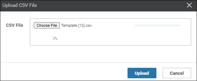
The next screen will indicate that the updated device template will be applied to the Cisco CSR 1000v routers within the transit VPC. An example is shown in the figure below.
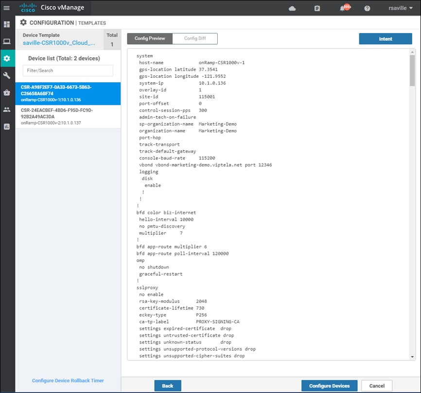
It is a good idea to preview the configuration by clicking on both devices listed in the navigation panel on the left side of the screen. This will validate the configurations before uploading them to the devices.
Step 26. Click on the Configure Devices button.
A pop-up window will appear, informing you that committing the changes will affect the configuration on the Cisco CSR 1000v routers within the transit VPC, and asking you to confirm that you want to proceed.
Step 27. Check the box next to Confirm configuration changes on 2 devices and click on the OK button.
The Task View screen will then appear. After a few moments the status of the Cisco CSR 1000v routers will appear as “Success” with a message indicating that the devices have been updated with the feature template configurations within the device template. An example is shown in the figure below.
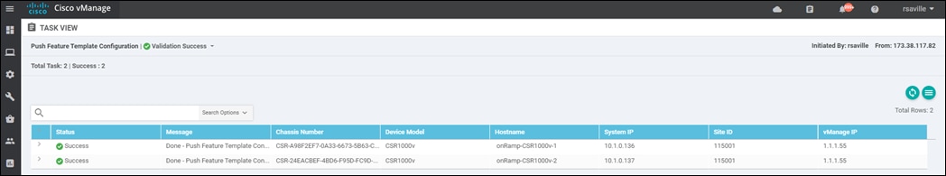
After a few minutes you should be able to go to the Site-to-Site VPN connections within the AWS console and see that all of the IPsec tunnels are now UP.
You should be able to verify that connectivity between EC2 instances within host VPCs 1 and 2 (IaaS-Spoke-1 and IaaS-Spoke-2) is allowed. However connectivity between EC2 instances within host VPC 3 and either host VPCs 1 or 2 is not allowed. An SSH connection cannot be established between these EC2 instances.
By configuring service VPN 1 on one simulated branch you should be able to verify connectivity to the first two host VPCs (IaaS-Spoke-1 and IaaS-Spoke-2) by establishing SSH connections from the branch to the EC2 instances within that host VPC. However, SSH connections from the simulated branch to the EC2 instances within the third host VPC (IaaS-Spoke-3) cannot be established.
By configuring service VPN 2 on the second simulated branch you should be able to verify connectivity to the third host VPC (IaaS-Spoke-3) by establishing SSH connections from the second branch to the EC2 instances within that host VPC. However, SSH connections from the second branch to the EC2 instances within the first two host VPCs (IaaS-Spoke-1 and IaaS-Spoke-2) cannot be established.
Appendix A: Changes from previous versions
This guide is updated from a previous version. This version covers both Cisco CSR 1000v virtual routers as well as Cisco vEdge Cloud routers deployed within a transit VPC. This guide also discusses the autoscaling feature which allows up to four pairs of Cisco SD-WAN Edge routers per transit VPC. Finally, a chapter discussing the manual connection of an AWS Transit Gateway to an existing transit VPC has been added at the end of the document before the Appendices.
Appendix B: Hardware and software used for validation
This guide was validated using the following hardware and software.
Table 11. Hardware and software for validation
| Functional Area |
Product |
Software version |
| Transit VPC SD-WAN router |
Cisco vEdge Cloud router |
19.3.0 |
|
|
Cisco CSR 1000v router |
17.2.1r |
| SD-WAN Control |
Cisco vBond, vSmart, and vManage |
20.1.1 |
Appendix C: Cisco SD-WAN Edge router configuration template summary
This deployment guide defines multiple feature templates as shown in the following table. Separate feature templates were created for Cisco vEdge routers and Cisco IOS XE SD-WAN routers.
Table 12. Templates used within this deployment guide
| Template Category |
Description |
| Cisco vEdge router shared feature templates |
Feature templates which are shared across all Cisco vEdge devices – both within the transit VPC, as well as the branch locations within the Cisco SD-WAN deployment. |
| Cisco vEdge Cloud router AWS transit VPC feature templates |
Feature templates which are specific to Cisco vEdge Cloud router instances created within an AWS transit VPC by Cisco Cloud onRamp for IaaS. |
| Cisco IOS XE SD-WAN shared feature templates |
Feature templates which are shared across all Cisco IOS XE SD-WAN based devices – both within the transit VPC, as well as the branch locations within the Cisco SD-WAN deployment. |
| Cisco CSR 1000v AWS transit VPC feature templates |
Feature templates which are specific to Cisco Cloud Services Router (CSR 1000v) instances created within an AWS transit VPC by Cisco Cloud onRamp for IaaS. |
Cisco vEdge templates
This section summarizes the feature and device templates for the Cisco vEdge and Cisco vEdge Cloud routers for this deployment guide.
Cisco vEdge feature templates
The following feature templates are common across Cisco vEdge and vEdge Cloud routers within the SD-WAN for this deployment guide. In other words, they apply not only to the Cisco vEdge Cloud routers within the transit VPC, but also to other physical and/or logical Cisco vEdge routers within the branch locations.
| Tech tip |
| The configuration of the physical and/or logical Cisco SD-WAN Edge routers within the branch locations are not discussed within this deployment guide. |
vEdge System feature template
Devices: All Cisco vEdge and ISR 1100 (Viptela OS) devices
Template: Basic Information / System
Template Name: saville-vEdge_System_Template
Description: vEdge System Template
Table 13. vEdge System feature template settings
| Section |
Parameter |
Type |
Variable/Value |
| Basic Configuration |
Site ID |
Device Specific |
system_site_id |
|
|
System IP |
Device Specific |
system_system_ip |
|
|
Hostname |
Device Specific |
system_host_name |
|
|
Device Groups |
Device Specific |
system_device_groups |
|
|
Console Baud Rate (bps) |
Global |
115200 |
| GPS |
Latitude |
Device Specific |
system_latitude |
|
|
Longitude |
Device Specific |
system_longitude |
| Advanced |
Port Hopping |
Device Specific |
system_port_hop |
|
|
Port Offset |
Device Specific |
system_port_offset |
|
|
Allow-Same-Site-Tunnel |
Global |
On or Off* |
* Please see the Site ID Configuration when Multiple Device Pairs are Implemented per Transit VPC section of this document for a discussion of the use of the Allow-Same-Site-Tunnel setting when multiple pairs of vEdge Cloud routers are instantiated within an AWS transit VPC.
Note that if you enable same-site-tunnels, you may wish to create a separate vEdge System feature template for vEdge Cloud devices within the transit VPC, in order to limit that setting only to the vEdge Cloud devices within the transit VPC.
vEdge NTP feature template
Devices: All Cisco vEdge and ISR 1100 (Viptela OS) devices, vManage, and vSmart
Template: Basic Information / NTP
Template Name: saville-vEdge_NTP_Template
Description: vEdge NTP Template
Table 14. vEdge NTP feature template settings
| Section |
Parameter |
Type |
Variable/Value |
| Server |
Hostname/IP Address |
Global |
time.nist.gov |
When a Cisco vEdge Cloud router first powers up within AWS, it should get its time from the physical server. However, being a virtual machine, the Cisco vEdge Cloud router time may drift. It is a good idea to sync the Cisco vEdge Cloud router time to an NTP server.
With Cisco Cloud onRamp for IaaS, the Cisco vEdge Cloud routers within the AWS transit VPC are automatically configured such that interface ge0/0 is part of VPN 0 and gets its IP address via DHCP (ip dhcp-client). The AWS DHCP server which allocates the IP address to ge0/0 will also provide the DNS server IP address. Therefore, a hostname can be configured if the hostname can be translated to an IP address by the AWS DNS server. For this deployment guide the NTP server time.nist.gov was used.
You should be careful to use only known and trusted NTP servers. Disruptions to time synchronizations can affect the ability of the Cisco vEdge Cloud routers within the transit VPC to connect to the vBond, vManage, and vSmart; as well as the ability to establish IPsec connections to other Cisco SD-WAN Edge routers.
vEdge AAA feature template
Devices: All Cisco vEdge and ISR 1100 (Viptela OS) devices
Template: Basic Information / AAA
Template Name: saville-vEdge_AAA_Template
Description: vEdge AAA Template
Table 15. vEdge AAA feature template settings
| Section |
Parameter |
Type |
Variable/Value |
| Authentication |
Authentication Order |
Drop-down |
local |
| Local |
User/admin/Password |
Global |
<your admin password> |
vEdge OMP feature template
Devices: All Cisco vEdge and ISR 1100 (Viptela OS) devices
Template: Basic Information / OMP
Template Name: saville-vEdge_OMP_Template
Description: vEdge OMP Template
Table 16. vEdge OMP feature template settings
| Section |
Parameter |
Type |
Variable/Value |
| Basic configuration |
Number of Paths Advertised per Prefix |
Global |
16 |
|
|
ECMP Limit |
Global |
16 |
| Advertise |
BGP |
Global |
On |
|
|
Connected |
Global |
Off |
|
|
Static |
Global |
Off* |
* Please see the Transit VPC to Host VPC Routing section of this document for a discussion of why redistribution of static routes into OMP is disabled within the AWS transit VPC for this guide.
Note that if you require static routes to be redistributed into OMP within the rest of your SD-WAN network, you may wish to create a separate vEdge OMP feature template for vEdge Cloud devices within the transit VPC in order to restrict redistribution of static routes into OMP only to the vEdge Cloud devices within the transit VPC.
vEdge Security feature template
Devices: All Cisco vEdge and ISR 1100 (Viptela OS) devices
Template: Basic Information / Security
Template Name: saville-vEdge_Security_Template
Description: vEdge Security Template
Table 17. vEdge Security feature template settings
| Section |
Parameter |
Type |
Variable/Value |
| Basic configuration |
Replay window |
Global / drop-down |
4096 |
vEdge VPN 1 Interface Ethernet Loopback0 feature template
Devices: All Cisco vEdge and ISR 1100 (Viptela OS) devices, vManage and vSmart
Template: VPN / VPN Interface Ethernet
Template Name: saville-vEdge_VPN1_Lo0
Description: vEdge Service VPN 1 Interface Loopback 0
Table 18. vEdge VPN 1 Interface Ethernet Loopback0 feature template settings
| Section |
Parameter |
Type |
Variable/Value |
| Basic Configuration |
Shutdown |
Global |
No |
|
|
Interface Name |
Global |
loopback0 |
| IPv4 Configuration |
IPv4 Address |
Radio Button |
Static |
|
|
IPv4 Address |
Device Specific |
vpn1_lo0_int_ip_addr|maskbits |
vEdge Banner feature template
Devices: All Cisco vEdge and ISR 1100 (Viptela OS) devices, vManage and vSmart
Template: Other Templates / Banner
Template Name: saville-vEdge_Banner_Template
Description: vEdge Banner Template
Table 19. vEdge Banner feature template settings
| Section |
Parameter |
Type |
Variable/Value |
| Basic Configuration |
MOTD Banner |
Global |
This is a private network. It is for authorized use only. |
vEdge SNMP feature template
Devices: All Cisco vEdge and ISR 1100 (Viptela OS) devices, vManage and vSmart
Template: Other Templates / SNMP
Template Name: saville-vEdge_SNMP_Template
Description: vEdge SNMP Template
Table 20. vEdge SNMP feature template settings
| Section |
Parameter |
Type |
Variable/Value |
| SNMP |
Shutdown |
Device Specific |
snmp_shutdown |
|
|
Name of Device for SNMP |
Device Specific |
snmp_device_name |
|
|
Location of Device |
Device Specific |
snmp_device_location |
| SNMP Version |
View/Name |
Radio Button |
V2 |
| View & Community |
View/Name |
Global |
isoALL |
|
|
View/Object Identifiers |
Global |
1.3.6.1 |
|
|
Community/Name |
Global |
c1sco123 |
|
|
Community/Authorization |
Global/Drop-down |
read-only |
|
|
Community/View |
Global |
isoALL |
| Trap |
Trap Group/Group Name |
Global |
SNMP-GRP |
|
|
Trap Group/Trap Type Modules/Module Name |
Global |
all |
|
|
Trap Group/Trap Type Modules/Severity Levels |
Global |
critical, major, minor |
| Trap Target (Optional) |
VPN ID |
Device Specific |
snmp_trap_vpn_id |
|
|
IP Address |
Device Specific |
snmp_trap_ip |
|
|
UDP Port |
Global |
162 |
|
|
Trap Group Name |
Global |
SNMP-GRP |
|
|
Community Name |
Global |
c1sco123 |
|
|
Source Interface |
Device Specific |
snmp_trap_source_interface |
vEdge Logging feature template
Devices: All vEdge and ISR 1100 (Viptela OS) devices, vManage, and vSmart
Template: Other Templates / Logging
Template Name: saville-vEdge_Logging_Template
Description: vEdge Logging Template
Table 21. vEdge Logging feature template settings
| Section |
Parameter |
Type |
Variable/Value |
| Server |
Hostname/IP Address |
Global |
10.1.0.68 |
|
|
VPN ID |
Device Specific |
logging_server_vpn |
|
|
Source Interface |
Global |
loopback0 |
Centrally logging information from the Cisco vEdge Cloud routers within the transit VPC, to a server within the campus may provide additional information when monitoring and/or troubleshooting issues related to connectivity to the AWS host VPCs. However, logging information across the IPsec VPN connections between the campus and the transit VPC will also increase AWS data transfer costs. You should balance out the requirement for central logging with the additional costs and decide appropriately.
vEdge AWS transit VPC feature templates
The following feature templates are unique to the Cisco vEdge Cloud routers within the transit VPC of this deployment guide.
vEdge BFD feature template
Devices: vEdge Cloud
Template: Basic Information / BFD_Template
Template Name: saville-vEdge_AWS_Transit_BFD_Template
Description: vEdge BFD Template for AWS Transit VPC vEdge Cloud Routers
Table 22. vEdge BFD feature template settings
| Section |
Parameter |
Type |
Variable/Value |
| Basic Configuration |
Poll Interval |
Global |
120000 |
| Color (Biz Internet) |
Color |
Drop-down |
Biz Internet |
|
|
Hello Interval (milliseconds) |
Device Specific |
biz_internet_bfd_hello_interval |
|
|
Path MTU |
Global |
Off |
The default BFD hello interval is 1,000 milliseconds. The BFD hello interval controls how fast the network converges in the case of an IPsec tunnel failure. The shorter the BFD hello interval, generally the faster the network recognizes a failure of one of the Cisco vEdge Cloud routers within the transit VPC and selects an alternate path. However, a shorter BFD hello interval also results in more control traffic from each Cisco SD-WAN Edge router within each branch site to the transit VPC Cisco vEdge Cloud routers. This adds to the AWS data transfer charges.
For the vEdge AWS_Transit_BFD_Template, only a color of Biz Internet has been configured, since Cisco Cloud onRamp for IaaS only provisions physical Internet connections to the transit VPC (VPN 0, interface ge0/0). The BFD hello interval has been made a variable. For this deployment guide, the BFD hello interval was set for 10,000 milliseconds. You should select the appropriate BFD hello interval to balance the requirement for fast convergence against the cost of additional data transfer charges in your deployment.
vEdge VPN 512 feature template
Devices: vEdge Cloud
Template: VPN / VPN
Template Name: saville-vEdge_AWS_Transit_VPN512_Template
Description: vEdge VPN 512 Out-of-Band Management for AWS Transit VPC vEdge Cloud Routers
Table 23. vEdge VPN512 feature template settings
| Section |
Parameter |
Type |
Variable/Value |
| Basic Configuration |
VPN |
Global |
512 |
|
|
Name |
Global |
Management VPN |
With Cisco Cloud onRamp, the Cisco SD-WAN Edge routers within the AWS transit VPC are automatically configured such that interface eth0 is in VPN 512 and gets its IP address via DHCP (ip dhcp-client). The AWS DHCP server which allocates the IP address to eth0 will also provide both the default gateway and the DNS server IP address for interface eth0. Therefore saville-vEdge_AWS_Transit_VPN512_Template has no static routes or DNS servers within it.
vEdge VPN 512 Interface Ethernet feature template
Devices: vEdge Cloud
Template: VPN / VPN Interface Ethernet
Template Name: saville-vEdge_AWS_Transit_VPN512_Interface
Description: vEdge VPN 512 Management Interface for AWS Transit vEdge Cloud Routers
Table 24. vEdge VPN512 Interface Ethernet feature template settings
| Section |
Parameter |
Type |
Variable/Value |
| Basic Configuration |
Shutdown |
Global |
No |
|
|
Interface Name |
Device Specific |
vpn512_mgmt_int |
|
|
Description |
Global |
Management Interface |
| IPv4 Configuration |
IPv4 Address |
Radio Button |
Dynamic |
Cisco Cloud onRamp does the following within AWS for management access to the Cisco vEdge Cloud routers:
● Creates a network interface named Viptela-Transit-Interface-0 on each Cisco vEdge Cloud router.
● Maps the network interface to the subnet corresponding to the management interface (VPN 512 eth0) of each Cisco vEdge Cloud router. The name of this subnet is Viptela-Transit-Subnet-0 on each Cisco vEdge Cloud router.
● Maps the network interface, Viptela-Transit-Interface-0, to the private IP address which was assigned to the eth0 interface by the AWS DHCP server for the subnet, Viptela-Transit-Subnet-0 on each Cisco vEdge Cloud router.
● Allocates four new Elastic IP addresses if there are none available within the AWS region. Otherwise it will use available Elastic IP addresses. A total of two Elastic IP addresses are required for the management interfaces (VPN 512 eth0) since there are two Cisco vEdge Cloud routers per transit VPC.
● Associates one Elastic IP address with the network interface, Viptela-Transit-Interface-0, on each Cisco vEdge Cloud router.
● Assigns the default security group of the VPC, Viptela-Transit-SecurityGroup, to the network interface. The AWS rules for the default security group are as follows:
◦ Allow all inbound traffic from other instances associated with the default security group.
◦ Allow all outbound traffic.
The default security group for the transit VPC, Viptela-Transit-SecurityGroup, does not allow inbound SSH connections to the management interface of the Cisco vEdge Cloud routers. To allow access, the security group must be modified to allow inbound SSH connections from the IP addresses in which you wish to manage the Cisco vEdge Cloud routers.
| Tech tip |
| The default AWS Security Group for the transit VPC, Viptela-Transit-SecurityGroup, also does not allow inbound SD-WAN IPsec VPN connections initiated from other Cisco SD-WAN Edge routers within the network, or inbound IKE-based (UDP 500) IPsec VPN connections initiated from AWS host VPCs. Since AWS host VPCs never initiate IKE-based IPsec VPN connections, there is no need to modify the default Security Group to allow UDP 500 inbound. IKE-based IPsec VPN connections between the Cisco SD-WAN Edge routers within the AWS transit VPC and the host VPCs are always initiated from the Cisco SD-WAN Edge routers within the AWS transit VPC. Since all outbound traffic is allowed by the default Security Group, and since the return traffic from those outbound sessions is also allowed, no modifications to the Viptela-Transit-SecurityGroup are needed. However, there are scenarios where inbound SD-WAN IPsec VPN connections initiated from other Cisco SD-WAN Edge routers within the network may need to be allowed within the default Viptela-Transit-SecurityGroup. Specifically, firewalls at a customer site (branch or campus) deployed in front of the Cisco SD-WAN Edge routers may prevent traffic originating from within the Internet from reaching the Cisco SD-WAN Edge routers. Likewise one-to-many NAT (otherwise known as Port-Address Translation [PAT]) implemented at the firewalls may prevent traffic originating from within the Internet from reaching the Cisco SD-WAN Edge routers. In such situations, the SD-WAN IPsec VPN connections between the SD-WAN Edge routers within the AWS transit VPC and the branch or campus locations cannot be initiated from within the transit VPC. The SD-WAN IPsec VPN connections need to be originated from the Cisco SD-WAN Edge routers behind the firewall and/or NAT device within the campus and branch locations. This requires a modification to the inbound rules of the default security group, Viptela-Transit-SecurityGroup, of the AWS transit VPC to allow such connections. Since both Cisco SD-WAN Edge devices will keep the default port offset of 0, the Cisco SD-WAN Edge devices can take on any 1 of 5 ports since port-hopping is enabled by default. You will need to modify the inbound security group rules and add the following: · Custom UDP Port range 12346 source 0.0.0.0/0 · Custom UDP Port range 12366 source 0.0.0.0/0 · Custom UDP Port range 12386 source 0.0.0.0/0 · Custom UDP port range 12406 source 0.0.0.0/0 · Custom UDP port range 12426 source 0.0.0.0/0 Note that the source is an IP address or subnet from the outside. In this case, since the source IP addresses of the branch or campus Cisco SD-WAN Edge routers may be unknown, or simply due to the scale of the number of entries you would need to configure if you were to try to allow specific IP addresses and ports being unfeasible; you can specify 0.0.0.0/0 in include any source IP address. The port that is specified above is a destination port (port on the Cisco SD-WAN Edge routers deployed within the AWS transit VPC). AWS Security Groups do not filter on source ports. Finally control traffic is initiated from the Cisco SD-WAN Edge routers within the AWS transit VPC. No adjustments need to be made for control traffic. |
vEdge VPN 0 feature template
Devices: vEdge Cloud
Template: VPN / VPN
Template Name: saville-vEdge_AWS_Transit_VPN0_Template
Description: vEdge VPN0 Transport Template for AWS Transit VPC vEdge Cloud Routers
Table 25. vEdge VPN0 feature template settings
| Section |
Parameter |
Type |
Variable/Value |
| Basic Configuration |
VPN |
Global |
0 |
|
|
Name |
Global |
Transport VPN |
With Cisco Cloud onRamp, the Cisco vEdge routers within the AWS transit VPC are automatically configured such that interface ge0/0 is in VPN 0 and gets its IP address via DHCP (ip dhcp-client). The AWS DHCP server which allocates the IP address to ge0/0 will also provide both the default gateway and the DNS server IP address for interface ge0/0. Therefore saville-vEdge_AWS_Transit_VPN0_Template has no static routes or DNS servers within it.
vEdge VPN 0 Interface Ethernet feature template
Devices: vEdge Cloud
Template: VPN / VPN Interface Ethernet
Template Name: saville-vEdge_AWS_Transit_VPN0_Interface
Description: vEdge VPN 0 Transport Interface for AWS Transit VPC vEdge Cloud Routers
Table 26. vEdge VPN0 Interface Ethernet feature template settings (Internet)
| Section |
Parameter |
Type |
Variable/Value |
| Basic Configuration |
Shutdown |
Device Specific |
vpn0_inet_int_shutdown |
|
|
Interface Name |
Device Specific |
vpn0_inet_int_gex|x |
|
|
Description |
Global |
Internet Interface |
| IPv4 Configuration |
IPv4 Address |
Radio Button |
Dynamic |
|
|
Bandwidth Upstream |
Device Specific |
vpn0_inet_int_bandwidth_up |
|
|
Bandwidth Downstream |
Device Specific |
vpn0_inet_int_bandwidth_down |
| Tunnel |
Tunnel Interface |
Global |
On |
|
|
Color |
Global |
biz-internet |
|
|
Allow Service>NTP |
Global |
On |
| Tunnel>Advanced Options>Encapsulation |
IPsec Preference |
Device Specific |
vpn0_inet_tunnel_ipsec_preference |
| Advanced |
TCP MSS |
Global |
1350 |
|
|
Clear-Don’t-Fragment |
Global |
On |
Cisco Cloud onRamp does the following within AWS for the Internet transport connections to the Cisco vEdge Cloud routers:
● Creates a network interface named Viptela-Transit-Interface-1 on each Cisco vEdge Cloud router.
● Maps the network interface to the subnet corresponding to the Internet transport interface (VPN 0 ge0/0) of each Cisco vEdge Cloud router. The name of this subnet is Viptela-Transit-Subnet-1 on each Cisco vEdge Cloud router.
● Maps the network interface, Viptela-Transit-Interface-1, to the private IP address which was assigned to the ge0/0 interface by the AWS DHCP server for the subnet, Viptela-Transit-Subnet-1 on each Cisco vEdge router.
● Allocates four new Elastic IP addresses if there are none available within the AWS region. Otherwise it will use available elastic IP addresses. A total of two Elastic IP addresses are required for the Internet transport interfaces (VPN 0 ge0/0), since there are two Cisco vEdge Cloud routers per transit VPC.
● Associates one Elastic IP address with the network interface, Viptela-Transit-Interface-1, on each Cisco vEdge Cloud router.
● Assigns the default security group of the VPC, Viptela-Transit-SecurityGroup, to the network interface. The AWS rules for the default security group are as follows:
◦ Allow all inbound traffic from other instances associated with the default security group.
◦ Allow all outbound traffic.
vEdge VPN 1 feature template
Devices: vEdge Cloud
Template: VPN / VPN
Template Name: saville-vEdge_AWS_Transit_VPN1_Template
Description: vEdge VPN1 Service Template for AWS Transit VPC vEdge Cloud Routers
Table 27. vEdge VPN1 feature template settings
| Section |
Parameter |
Type |
Variable/Value |
| Basic Configuration |
VPN |
Global |
1 |
|
|
Name |
Global |
Service VPN 1 |
|
|
Enhance ECMP Keying |
Global |
On |
| Advertise OMP |
BGP (IPv4) |
Global |
On |
|
|
Connected (IPv4) |
Global |
On |
BGP routes are advertised within OMP for service VPN 1. Connected routes are also advertised within OMP so that the IP addresses of the Loopback0 interfaces, which are part of VPN 1, are visible across the network.
vEdge VPN 2 feature template
Devices: vEdge Cloud
Template: VPN / VPN
Template Name: saville-vEdge_AWS_Transit_VPN2_Template
Description: vEdge VPN2 Service Template for AWS Transit VPC vEdge Cloud Routers
Table 28. VPN2 feature template settings
| Section |
Parameter |
Type |
Variable/Value |
| Basic Configuration |
VPN |
Global |
2 |
|
|
Name |
Global |
Service VPN 2 |
|
|
Enhance ECMP Keying |
Global |
On |
| Advertise OMP |
BGP (IPv4) |
Global |
On |
BGP routes are advertised within OMP for service VPN 2.
AWS transit VPC vEdge device template
The following table summarizes the device template for the Cisco vEdge Cloud routers deployed within the AWS transit VPC.
Device Model: vEdge Cloud
Template Name: saville-vEdge_Cloud_OnRamp_Transit_VPC
Description: vEdge Template for Cloud OnRamp for IaaS Routers in a Transit VPC
Table 29. Transit VPC device template: saville-vEdge_Cloud_onRamp_Transit_VPC
| Template Type |
Template Sub-Type |
Template Name |
| System |
|
saville-vEdge_System_Template |
|
|
Logging |
saville-vEdge_Logging_Template |
|
|
NTP |
saville-vEdge_NTP_Template |
|
|
AAA |
saville-vEdge_AAA_Template |
| BFD |
|
saville-vEdge_AWS_Transit_BFD_Template |
| OMP |
|
saville-vEdge_OMP_Template |
| Security |
|
saville-vEdge_Security_Template |
| VPN0 |
|
saville-vEdge_AWS_Transit_VPN0_Template |
|
|
VPN Interface |
saville-vEdge_AWS_Transit_VPN0_Interface |
| VPN512 |
|
saville-vEdge_AWS_Transit_VPN512_Template |
|
|
VPN Interface |
saville-vEdge_AWS_Transit_VPN512_Interface |
| VPN1 |
|
saville-vEdge_AWS_Transit_VPN1_Template |
|
|
VPN Interface |
saville-vEdge_VPN1_Lo0 |
| VPN2 |
|
saville-vEdge_AWS_Transit_VPN2_Template |
| Banner |
|
saville-vEdge_Banner_Template |
| SNMP |
|
saville-vEdge_SNMP_Template |
| Tech tip |
| Cisco Cloud onRamp for IaaS dynamically generates the equivalent configuration that would be found in a BGP feature template and two VPN Interface IPsec feature templates applied to one or more service VPNs – when a host VPC is mapped to the transit VPC. Because of this, it is recommended that you do not configure BGP feature templates or VPN Interface IPsec feature templates for the service VPNs within the device template attached to the Cisco vEdge Cloud routers before instantiating a transit VPC through Cisco Cloud onRamp for IaaS. Cisco Cloud onRamp for IaaS uses BGP ASN 9988 for the Cisco vEdge Cloud routers within the transit VPC. If you do attach a BGP feature template to a service VPN within the device template attached to the Cisco vEdge Cloud routers within the transit VPC, and if you specify a BGP ASN other than 9988, Cisco Cloud onRamp for IaaS may indicate that the host VPC has been successfully mapped to the transit VPC. However, the IPsec tunnels may not become active. This is because the configuration changes necessary to support the IPsec VPN connections and BGP peering may not be successfully pushed to the Cisco vEdge Cloud routers within the transit VPC due to the conflict in BGP ASN. Cisco Cloud onRamp for IaaS dynamically generates ipsec interface numbers which are used for the IPsec VPN connections to the host VPC. Typically the ipsec interface numbers begin at interface ipsec1 and increment up as additional host VPCs are mapped to the Cisco vEdge Cloud routers within the transit VPC. If you do attach a VPN Interface IPsec feature template to a service VPN within the device template attached to the Cisco vEdge Cloud routers within the transit VPC, and if you specify an ipsec interface number which overlaps with what Cisco Cloud onRamp for IaaS configures, Cisco Cloud onRamp for IaaS may indicate that the host VPC has been successfully mapped to the transit VPC. However, the IPsec tunnels may not become active. This is because the configuration changes necessary to support the IPsec VPN connections and BGP peering may not be successfully pushed to the Cisco vEdge Cloud routers within the transit VPC due to the conflict in ipsec interface numbers. |
| Tech tip |
| No QoS or routing policies were configured for this deployment guide. This was done simply to focus this deployment guide on the Cisco Cloud onRamp for IaaS feature. In a production environment, you should configure the appropriate QoS and routing policies for your Cisco SD-WAN deployment. |
Cisco IOS XE SD-WAN templates
This section summarizes the feature and device templates for the Cisco IOS XE SD-WAN routers for this deployment guide.
Cisco IOS XE SD-WAN feature templates
The following feature templates are common across Cisco IOS XE SD-WAN routers for this deployment guide. In other words, they apply not only to the Cisco CSR 1000v routers within the transit VPC, but also to other physical and/or logical Cisco IOS XE SD-WAN routers within branch locations.
| Tech tip |
| The configuration of the physical and/or logical Cisco SD-WAN Edge routers within the branch locations are not discussed within this deployment guide. |
IOS XE SD-WAN Cisco System feature template
Devices: All ASR1K, C1100, CSR1000v, ENCS-5400, IR1101, ISR4K, and ISRv
Template: Basic Information / Cisco System
Template Name: saville-IOS-XE_Cisco_System_Template
Description: IOS XE SD-WAN Cisco System Template
Table 30. IOS XE SD-WAN Cisco System feature template settings
| Section |
Parameter |
Type |
Variable/Value |
| Basic Configuration |
Site ID |
Device Specific |
system_site_id |
|
|
System IP |
Device Specific |
system_system_ip |
|
|
Hostname |
Device Specific |
system_host_name |
|
|
Device Groups |
Device Specific |
system_device_groups |
|
|
Console Baud Rate (bps) |
Global |
115200 |
| GPS |
Latitude |
Device Specific |
system_latitude |
|
|
Longitude |
Device Specific |
system_longitude |
| Advanced |
Port Hopping |
Device Specific |
system_port_hop |
|
|
Port Offset |
Device Specific |
system_port_offset |
IOS XE SD-WAN Cisco NTP feature template
Devices: All ASR1K, C1100, CSR1000v, ENCS-5400, IR1101, ISR4K, and ISRv
Template: Basic Information/Cisco NTP
Template Name: saville-IOS-XE_Cisco_NTP_Template
Description: IOS XE SD-WAN CISCO NTP Template
Table 31. IOS XE SD-WAN Cisco NTP feature template settings
| Section |
Parameter |
Type |
Variable/Value |
| Server |
Hostname/IP Address |
Global |
time.nist.gov |
When a Cisco CSR 1000v router first powers up within AWS, it should get its time from the physical server. However, being a virtual machine, the Cisco CSR 1000v router time may drift. It is a good idea to sync the Cisco CSR 1000v router time to an NTP server.
With Cisco Cloud onRamp for IaaS, the Cisco CSR 1000v routers within the AWS transit VPC must be configured such that interface GigabitEthernet2 is part of VPN 0 (transport VPN). Interface GigabitEthernet2 will automatically get its IP address via DHCP (ip dhcp-client). The AWS DHCP server which allocates the IP address to GigabitEthernet2 will also provide the DNS server IP address. Therefore, a hostname can be configured if the hostname can be translated to an IP address by the AWS DNS server. For this deployment guide the NTP server time.nist.gov was used.
You should be careful to use only known and trusted NTP servers. Disruptions to time synchronizations can affect the ability of the Cisco CSR 1000v routers within the transit VPC to connect to the vBond, vManage, and vSmart; as well as the ability to establish IPsec connections to other Cisco SD-WAN Edge routers.
IOS XE SD-WAN Cisco AAA feature template
Devices: All ASR1K Series, ISR4K Series, ISRv, Cisco 1100 Series, CSR1000v,
IR1101, and ENCS-5400
Template: Basic Information / Cisco AAA
Template Name: saville-IOS-XE_Cisco_AAA_Template
Description: IOS XE SD-WAN Cisco AAA Template
Table 32. IOS XE SD-WAN Cisco AAA feature template settings
| Section |
Parameter |
Type |
Variable/Value |
| Local |
User/admin/Password |
Global |
<your admin password> |
|
|
User/admin/Privilege |
Global |
15 |
| Authentication Order |
ServerGroups priority order |
Global |
local |
IOS XE SD-WAN Cisco OMP feature template
Devices: All ASR1K Series, ISR4K Series, ISRv, Cisco 1100 Series, CSR1000v, and
IR1101
Template: Basic Information / Cisco OMP
Template Name: saville-IOS-XE_Cisco_OMP_Template
Description: IOS XE SD-WAN Cisco OMP Template
Table 33. IOS XE SD-WAN Cisco OMP feature template settings
| Section |
Parameter |
Type |
Variable/Value |
| Basic configuration |
Number of Paths Advertised per Prefix |
Global |
16 |
|
|
ECMP Limit |
Global |
16 |
| Advertise |
Connected |
Global |
Off |
|
|
Static |
Global |
Off* |
* Please see the Transit VPC to Host VPC Routing section of this document for a discussion of why redistribution of static routes into OMP is disabled within the AWS transit VPC for this guide.
Note that if you require static routes to be redistributed into OMP within the rest of your SD-WAN network, you may wish to create a separate Cisco OMP feature template for Cisco CSR 1000v devices within the transit VPC in order to restrict redistribution of static routes into OMP only to the Cisco CSR 1000v devices within the transit VPC.
IOS XE SD-WAN Cisco Security feature template
Devices: All ASR1K Series, ISR4K Series, ISRv, Cisco 1100 Series, CSR1000v,
IR1101, and C8200-UCPE-1N8
Template: Basic Information / Cisco Security
Template Name: saville-IOS-XE_Cisco_Security_Template
Description: IOS XE SD-WAN Cisco Security Template
Table 34. IOS XE SD-WAN Cisco Security feature template settings
| Section |
Parameter |
Type |
Variable/Value |
| Basic configuration |
Replay window |
Global / drop-down |
4096 |
IOS XE SD-WAN VPN 1 Interface Ethernet Loopback0 feature template
Devices: All ASR1K Series, ISR4K Series, ISRv, Cisco 1100 Series, CSR1000v,
ENCS-5400, and IR1101,
Template: VPN / VPN Interface Ethernet
Template Name: saville-IOS-XE_VPN1_Lo0
Description: IOS XE SD-WAN Service VPN 1 Interface Loopback 0
Table 35. IOS XE SD-WAN VPN 1 Interface Ethernet Loopback0 feature template settings
| Section |
Parameter |
Type |
Variable/Value |
| Basic Configuration |
Shutdown |
Global |
No |
|
|
Interface Name |
Global |
loopback0 |
| IPv4 Configuration |
IPv4 Address |
Radio Button |
Static |
|
|
IPv4 Address |
Device Specific |
vpn1_lo0_int_ip_addr|maskbits |
IOS XE SD-WAN Cisco Banner feature template
Devices: All ASR1K Series, ISR4K Series, ISRv, Cisco 1100 Series, CSR1000v,
and IR1101
Template: Other Templates / Cisco Banner
Template Name: saville-IOS-XE_Cisco_Banner_Template
Description: IOS XE SD-WAN Cisco Banner Template
Table 36. IOS XE SD-WAN Cisco Banner feature template settings
| Section |
Parameter |
Type |
Variable/Value |
| Basic Configuration |
MOTD Banner |
Global |
This is a private network. It is for authorized use only. |
IOS XE SD-WAN Cisco SNMP feature template
Devices: All ASR1K Series, ISR4K Series, ISRv, Cisco 1100 Series, CSR1000v, and IR1101
Template: Other Templates / SNMP
Template Name: saville-IOS-XE_Cisco_SNMP_Template
Description: IOS XE SD-WAN Cisco SNMP Template
Table 37. IOS XE SD-WAN SNMP feature template settings
| Section |
Parameter |
Type |
Variable/Value |
| SNMP |
Shutdown |
Device Specific |
snmp_shutdown |
|
|
Name of Device for SNMP |
Device Specific |
snmp_device_name |
|
|
Location of Device |
Device Specific |
snmp_device_location |
| SNMP Version |
SNMP Version |
Radio Button |
V2 |
| View & Community |
View/Name |
Global |
isoALL |
|
|
View/Name/Object Identifiers |
Global |
1.3.6.1 |
|
|
Community/Name |
Global |
c1sco123 |
|
|
Community/Authorization |
Global/Drop-down |
read-only |
|
|
Community/View |
Global |
isoALL |
| Trap Target (Optional) |
VPN ID |
Device Specific |
snmp_trap_vpn_id |
|
|
IP Address |
Device Specific |
snmp_trap_ip |
|
|
UDP Port |
Global |
162 |
|
|
Community Name |
Global |
c1sco123 |
|
|
Source Interface |
Device Specific |
snmp_trap_source_interface |
IOS XE SD-WAN Logging feature template
Devices: All ASR1K, C1100, CSR1000v, ENCS-5400, IR1101, ISR4K, and ISRv
Template: Other Templates / Cisco Logging
Template Name: saville-IOS-XE_Cisco_Logging_Template
Description: IOS XE SD-WAN Cisco Logging Template
Table 38. IOS XE SD-WAN Cisco Logging feature template settings
| Section |
Parameter |
Type |
Variable/Value |
| Server |
Hostname/IP Address |
Global |
10.1.0.68 |
|
|
VPN ID |
Device Specific |
logging_server_vpn |
|
|
Source Interface |
Global |
loopback0 |
Centrally logging information from the Cisco CSR 1000v routers within the transit VPC, to a server within the campus may provide additional information when monitoring and/or troubleshooting issues related to connectivity to the AWS host VPCs. However, logging information across the IPsec VPN connections between the campus and the transit VPC will also increase AWS data transfer costs. You should balance out the requirement for central logging with the additional costs and decide appropriately.
IOS XE SD-WAN AWS transit VPC feature templates
The following feature templates are unique to the Cisco CSR 1000v routers within the transit VPC of this deployment guide.
IOS XE SD-WAN Cisco BFD feature template
Devices: CSR1000v
Template: Basic Information / Cisco BFD Template
Template Name: saville-IOS-XE_AWS_Transit_Cisco_BFD_Template
Description: IOS XE SD-WAN Cisco BFD Template for AWS Transit VPC CSR 1000v Routers
Table 39. IOS XE SD-WAN Cisco BFD feature template settings
| Section |
Parameter |
Type |
Variable/Value |
| Basic Configuration |
Poll Interval |
Global |
120000 |
| Color (Biz Internet) |
Color |
Drop-down |
Biz Internet |
|
|
Hello Interval (milliseconds) |
Device Specific |
biz_internet_bfd_hello_interval |
|
|
Path MTU |
Global |
Off |
The default BFD hello interval is 1,000 milliseconds. The BFD hello interval controls how fast the network converges in the case of an IPsec tunnel failure. The shorter the BFD hello interval, generally the faster the network recognizes a failure of one of the Cisco CSR 1000v routers within the transit VPC and selects an alternate path. However, a shorter BFD hello interval also results in more control traffic from each Cisco SD-WAN Edge router within each branch site to the transit VPC Cisco CSR 1000v routers. This adds to the AWS data transfer charges.
For the saville-IOS-XE_AWS_Transit_BFD_Template, only a color of Biz Internet has been configured, since Cisco Cloud onRamp only provisions physical Internet connections to the transit VPC (VPN 0, interface GigabitEthernet3). The BFD hello interval has been made a variable. For this deployment guide, the BFD hello interval was set for 10,000 milliseconds. You should select the appropriate BFD hello interval to balance the requirement for fast convergence against the cost of additional data transfer charges in your deployment.
IOS XE SD-WAN VPN 512 feature template
Devices: CSR1000v
Template: VPN / Cisco VPN
Template Name: saville-IOS-XE_AWS_Transit_VPN512_Template
Description: IOS XE SD-WAN VPN 512 Out-of-Band Management for AWS Transit VPC CSR 1000v Routers
Table 40. IOS XE SD-WAN VPN512 feature template settings
| Section |
Parameter |
Type |
Variable/Value |
| Basic Configuration |
VPN |
Global |
512 |
|
|
Name |
Global |
Management VPN |
With Cisco Cloud onRamp, the Cisco CSR 1000v routers within the AWS transit VPC must be configured such that interface GigabitEthernet1 is in VPN 512. Interface GigabitEthernet1 will automatically get its IP address via DHCP (ip dhcp-client). The AWS DHCP server which allocates the IP address to GigabitEthernet1 will also provide both the default gateway and the DNS server IP address for interface GigabitEthernet1. Therefore saville-IOS-XE_AWS_Transit_VPN512_Template has no static routes or DNS servers within it.
IOS-XE VPN 512 Interface Ethernet feature template
Devices: CSR1000v
Template: VPN / Cisco VPN Interface Ethernet
Template Name: saville-IOS-XE_AWS_Transit_VPN512_Interface
Description: IOS XE SD-WAN VPN 512 Management Interface for AWS Transit CSR 1000v Routers
Table 41. IOS XE SD-WAN VPN512 Interface Ethernet feature template settings
| Section |
Parameter |
Type |
Variable/Value |
| Basic Configuration |
Shutdown |
Global |
No |
|
|
Interface Name |
Device Specific |
vpn512_mgmt_int |
|
|
Description |
Global |
Management Interface |
| IPv4 Configuration |
IPv4 Address |
Radio Button |
Dynamic |
Cisco Cloud onRamp does the following within AWS for management access to the Cisco CSR 1000v routers:
● Creates a network interface named Viptela-Transit-Interface-0 on each Cisco CSR 1000v router.
● Maps the network interface to the subnet corresponding to the management interface (VPN 512 GigabitEthernet1) of each Cisco CSR 1000v router. The name of this subnet is Viptela-Transit-Subnet-0 on each Cisco CSR 1000v router.
● Maps the network interface, Viptela-Transit-Interface-0, to the private IP address which was assigned to the GigabitEthernet1 interface by the AWS DHCP server for the subnet, Viptela-Transit-Subnet-0 on each Cisco CSR 1000v router.
● Allocates four new Elastic IP addresses if there are none available within the AWS region. Otherwise it will use available Elastic IP addresses. A total of two Elastic IP addresses are required for the management interfaces (VPN 512 GigabitEthernet1) since there are two Cisco CSR 1000v routers per transit VPC.
● Associates one Elastic IP address with the network interface, Viptela-Transit-Interface-0, on each Cisco CSR 1000v router.
● Assigns the default security group of the VPC, Viptela-Transit-SecurityGroup, to the network interface. The AWS rules for the default security group are as follows:
◦ Allow all inbound traffic from other instances associated with the default security group.
◦ Allow all outbound traffic.
The default security group for the transit VPC, Viptela-Transit-SecurityGroup, does not allow inbound SSH connections to the management interface of the Cisco CSR 1000v routers. To allow access, the security group must be modified to allow inbound SSH connections from the IP addresses in which you wish to manage the Cisco CSR 1000v routers.
IOS XE SD-WAN VPN 0 feature template
Devices: CSR1000v
Template: VPN / Cisco VPN
Template Name: saville-IOS-XE_AWS_Transit_VPN0_Template
Description: IOS XE SD-WAN VPN0 Transport Template for AWS Transit VPC WAN Edge Routers
Table 42. IOS XE SD-WAN VPN0 feature template settings
| Section |
Parameter |
Type |
Variable/Value |
| Basic Configuration |
VPN |
Global |
0 |
|
|
Name |
Global |
Transport VPN |
With Cisco Cloud onRamp, the Cisco CSR 1000v routers within the AWS transit VPC must be configured such that interface GigabitEthernet2 is in VPN 0 (transport VPN). GigabitEthernet2 will automatically get its IP address via DHCP (ip dhcp-client). The AWS DHCP server which allocates the IP address to GigabitEthernet2 will also provide both the default gateway and the DNS server IP address for interface GigabitEthernet2. Therefore saville-IOS-XE_AWS_Transit_VPN0_Template has no static routes or DNS servers within it.
IOS XE SD-WAN VPN 0 interface feature template
Devices: CSR1000v
Template: VPN / Cisco VPN Interface Ethernet
Template Name: saville-IOS-XE_AWS_Transit_VPN0_Interface
Description: IOS XE SD-WAN VPN 0 Transport Interface for AWS Transit VPC CSR 1000v Routers
Table 43. IOS XE SD-WAN VPN0 interface feature template settings (Internet)
| Section |
Parameter |
Type |
Variable/Value |
| Basic Configuration |
Shutdown |
Device Specific |
vpn0_inet_int_shutdown |
|
|
Interface Name |
Device Specific |
vpn0_inet_int_gex|x |
|
|
Description |
Global |
Internet Interface |
| IPv4 Configuration |
IPv4 Address |
Radio Button |
Dynamic |
|
|
Bandwidth Upstream |
Device Specific |
vpn0_inet_int_bandwidth_up |
|
|
Bandwidth Downstream |
Device Specific |
vpn0_inet_int_bandwidth_down |
| Tunnel |
Tunnel Interface |
Global |
On |
|
|
Color |
Global |
biz-internet |
|
|
Allow Service>All |
Global |
On |
| Tunnel>Advanced Options>Encapsulation |
IPsec Preference |
Device Specific |
vpn0_inet_tunnel_ipsec_preference |
| Advanced |
TCP MSS |
Global |
1350 |
Cisco Cloud onRamp does the following within AWS for the Internet transport connections to the Cisco CSR 1000v routers:
● Creates a network interface named Viptela-Transit-Interface-1 on each Cisco CSR 1000v router.
● Maps the network interface to the subnet corresponding to the Internet transport interface (VPN 0 GigabitEthernet2) of each Cisco CSR 1000v router. The name of this subnet is Viptela-Transit-Subnet-1 on each Cisco CSR 1000v router.
● Maps the network interface, Viptela-Transit-Interface-1, to the private IP address which was assigned to the GigabitEthernet2 interface by the AWS DHCP server for the subnet, Viptela-Transit-Subnet-1 on each Cisco CSR 1000v router.
● Allocates two new Elastic IP addresses if there are none available within the AWS region. Otherwise it will use available Elastic IP addresses. A total of two Elastic IP addresses are required for the Internet transport interfaces (VPN 0 GigabitEthernet2), since there are two Cisco CSR 1000v routers per transit VPC.
● Associates one Elastic IP address with the network interface, Viptela-Transit-Interface-1, on each Cisco CSR 1000v router.
● Assigns the default security group of the VPC, Viptela-Transit-SecurityGroup, to the network interface. The AWS rules for the default security group are as follows:
◦ Allow all inbound traffic from other instances associated with the default security group.
◦ Allow all outbound traffic.
| Tech tip |
| For Cisco vManage release 20.1.1 and Cisco IOS XE SD-WAN release 17.2.1r used for this deployment guide, it was necessary to configure Allow Service – All on the Tunnel of the Cisco VPN Interface Ethernet template for VPN0. This allowed the IPsec connections initiated from the Cisco CSR 1000v routers within the transit VPC to be established to the host VPCs. This issue is expected to be resolved in a future release of Cisco vManage / IOS XE SD-WAN, and not require this configuration. Note that this configuration is not considered to pose a security risk, since Cisco Cloud onRamp for IaaS creates the AWS Security Group, Viptela-Transit-SecurityGroup, and assigns it to the network interfaces of the Cisco CSR 1000v routers within the transit VPC. The rules for the Viptela-Transit-SecurityGroup allows all inbound traffic from other instances associated with the same security group (which is just the other Cisco CSR 1000v routers within the transit VPC) and also allows all outbound traffic. |
IOS XE SD-WAN VPN 1 feature template
Devices: CSR1000v
Template: VPN / Cisco VPN
Template Name: saville-IOS-XE_AWS_Transit_VPN1_Template
Description: IOS XE SD-WAN VPN1 Service Template for AWS Transit VPC CSR 1000v Routers
Table 44. IOS XE SD-WAN VPN1 feature template settings
| Section |
Parameter |
Type |
Variable/Value |
| Basic Configuration |
VPN |
Global |
1 |
|
|
Name |
Global |
Service VPN 1 |
|
|
Enhance ECMP Keying |
Global |
On |
| Advertise OMP |
BGP (IPv4) |
Global |
On |
|
|
Connected (IPv4) |
Global |
On |
BGP routes are advertised within OMP for service VPN 1. Connected routes are also advertised within OMP so that the IP addresses of the Loopback0 interfaces, which are part of VPN 1, are visible across the network.
| Tech tip |
| Re-distribution of BGP routes into OMP can be controlled both within the OMP feature template and the VPN template for the given service VPN. For IOS XE devices the behavior appears to be a logical OR as of vManage release 20.1.1. Hence, if you wish to control redistribution of BGP routes into OMP on a per-service VPN level, then globally disable BGP re-distribution at the OMP feature template and enable BGP re-distribution within each VPN template for each of the service VPNs which require the redistribution – as was done for this deployment guide. |
VPN 2 feature template
Devices: CSR1000v
Template: VPN / Cisco VPN
Template Name: saville-AWS_Transit_VPN2_Template
Description: VPN2 Service Template for AWS Transit VPC vEdge Cloud Routers
Table 45. VPN2 feature template settings
| Section |
Parameter |
Type |
Variable/Value |
| Basic Configuration |
VPN |
Global |
2 |
|
|
Name |
Global |
Service VPN 2 |
|
|
Enhance ECMP Keying |
Global |
On |
| Advertise OMP |
BGP (IPv4) |
Global |
On |
BGP routes are advertised within OMP for service VPN 2.
Cli Add-On feature template
Devices: CSR1000v
Template: Cli Add-On Template
Template Name: saville-IOS-XE_AWS_Transit_Cli_Add-On_Template
Description: CLI Template for Licensing of CSR 1000v Routers
Table 46. CLI feature template settings
| Section |
Configuration Command |
| CLI Configuration |
ip http client source-interface GigabitEthernet1 |
|
|
system allow-same-site-tunnel |
* Please see the Site ID Configuration when Multiple Device Pairs are Implemented per Transit VPC section of this document for a discussion of the use of the Allow-Same-Site-Tunnel setting when multiple pairs of Cisco CSR 1000V routers are instantiated within an AWS transit VPC.
Cisco CSR 1000v routers instantiated within AWS have a default IPsec throughput of 250 Mbps. For higher throughput the CSR 1000v must connect to the Cisco Smart Licensing server. The following document provides additional detail:
The CLI Add-On feature template is used to tell the CSR 1000v routers within the transit VPC which interface to use as the source interface for traffic sourced from the HTTPS client within the CSR 1000v routers.
For this deployment guide the VPN 512 Management interface (GigabitEthernet1) was used as the source interface for the Cisco call-home feature which is used for Smart Licensing. The interface chosen as the source for HTTPS client traffic must have Internet access and must have a DNS server capable of resolving “tools.cisco.com” to an IP address.
Optionally, the CLI Add-On feature template can also be used to allow same-site tunnels between the Cisco CSR 1000v routers within the AWS transit VPC, when multiple pairs of Cisco CSR 1000v routers are instantiated within the transit VPC and when all of the Cisco CSR 1000v routers are configured with the same Site ID.
AWS transit VPC CSR 1000v device template
The following table summarizes the device template for the Cisco CSR 1000v routers deployed within the AWS transit VPC.
Device Model: CSR1000v
Template Name: saville-CSR1000v_Cloud_OnRamp_Transit_VPC
Description: CSR 1000v Template for Cloud OnRamp for IaaS Routers in a Transit VPC
Table 47. Transit VPC device template: saville-CSR1000v_Cloud_onRamp_Transit_VPC
| Template Type |
Template Sub-Type |
Template Name |
| Cisco System |
|
saville-IOS-XE_Cisco_System_Template |
|
|
Cisco Logging |
saville-IOS-XE_Cisco_Logging_Template |
|
|
Cisco NTP |
saville-IOS-XE_Cisco_NTP_Template |
|
|
Cisco AAA |
saville-IOS-XE_Cisco_AAA_Template |
| Cisco BFD |
|
saville-IOS-XE_Cisco_AWS_Transit_BFD_Template |
| Cisco OMP |
|
saville-IOS-XE_Cisco_OMP_Template |
| Cisco Security |
|
saville-IOS-XE_Cisco_Security_Template |
| Cisco VPN |
|
saville-IOS-XE_AWS_Transit_VPN0_Template |
|
|
Cisco VPN Interface Ethernet |
saville-IOS-XE_AWS_Transit_VPN0_Interface |
| Cisco VPN |
|
saville-IOS-XE_AWS_Transit_VPN512_Template |
|
|
Cisco VPN Interface Ethernet |
saville-IOS-XE_AWS_Transit_VPN512_Interface |
| Cisco VPN |
|
saville-IOS-XE_AWS_Transit_VPN1_Template |
|
|
VPN Interface Ethernet |
saville-IOS-XE_VPN1_Lo0 |
| Cisco VPN |
|
saville-IOS-XE_AWS_Transit_VPN2_Template |
| Cisco Banner |
|
saville-IOS-XE_Cisco_Banner_Template |
| Cisco SNMP |
|
saville-IOS-XE_Cisco_SNMP_Template |
| Cisco Cli Add-On |
|
saville-IOS-XE_AWS_Transit_Cli_Add-On_Template |
| Tech tip |
| Cisco Cloud onRamp for IaaS dynamically generates the equivalent configuration that would be found in a Cisco BGP feature template and two Cisco VPN Interface IPsec feature templates applied to one or more service VPNs – when a host VPC is mapped to the transit VPC. Because of this, it is recommended that you do not configure Cisco BGP feature templates or Cisco VPN Interface IPsec feature templates for the service VPNs within the device template attached to the Cisco CSR 1000v routers before instantiating a transit VPC through Cisco Cloud onRamp for IaaS. Cisco Cloud onRamp for IaaS uses BGP ASN 9988 for the Cisco CSR 1000v routers within the transit VPC. If you do attach a Cisco BGP feature template to a service VPN within the device template attached to the Cisco CSR 1000v routers within the transit VPC, and if you specify a BGP ASN other than 9988, Cisco Cloud onRamp for IaaS may indicate that the host VPC has been successfully mapped to the transit VPC. However, the IPsec tunnels may not become active. This is because the configuration changes necessary to support the IPsec VPN connections and BGP peering may not be successfully pushed to the Cisco CSR 1000v routers within the transit VPC due to the conflict in BGP ASN. Cisco Cloud onRamp for IaaS dynamically generates Tunnel interface numbers which are used for the IPsec VPN connections to the host VPC. Typically the Tunnel interface numbers begin at interface Tunnel100001 and increment up as additional host VPCs are mapped to the Cisco CSR 1000v routers within the transit VPC. If you do attach a Cisco VPN Interface IPsec feature template to a service VPN within the device template attached to the Cisco CSR 1000v routers within the transit VPC, and if you specify a tunnel interface number which overlaps with what Cisco Cloud onRamp for IaaS configures, Cisco Cloud onRamp for IaaS may indicate that the host VPC has been successfully mapped to the transit VPC. However, the IPsec tunnels may not become active. This is because the configuration changes necessary to support the IPsec VPN connections and BGP peering may not be successfully pushed to the Cisco CSR 1000v routers within the transit VPC due to the conflict in Tunnel interface numbers. |
| Tech tip |
| No QoS or routing policies were configured for this deployment guide. This was done simply to focus this deployment guide on the Cisco Cloud onRamp feature. In a production environment, you should configure the appropriate QoS and routing policies for your Cisco SD-WAN deployment. |
Appendix D: Transit VPC Cisco SD-WAN Edge router CLI configuration
Cisco CSR 1000v router
The following is an example CLI configuration generated for a Cisco CSR 1000v router, based upon assigning the saville-CSR1000v_Cloud_OnRamp_Transit_VPC device template, and mapping host VPC IaaS-Spoke-1 to service VPN 1 and host VPC IaaS-Spoke-2 to service VPN 2.
The configuration commands highlighted in bold are additions or modifications to the configuration dynamically generated by Cisco Cloud onRamp for IaaS when mapping the host VPCs to the transit VPC. Note that the highlighted part of the configuration is not based upon the saville-CSR1000v_Cloud_OnRamp_Transit_VPC device template assigned the Cisco CSR 1000v routers.
onRamp-CSR1000v-1#show sdwan running-config
system
gps-location latitude 37.3541
gps-location longitude -121.9552
system-ip 10.1.0.136
overlay-id 1
site-id 115001
port-offset 0
control-session-pps 300
admin-tech-on-failure
sp-organization-name Marketing-Demo
organization-name Marketing-Demo
port-hop
track-transport
track-default-gateway
console-baud-rate 115200
vbond vbond-marketing-demo.viptela.net port 12346
!
banner motd \x03This is a private network. It is for authorized use only.\x03
service tcp-keepalives-in
service tcp-keepalives-out
no service tcp-small-servers
no service udp-small-servers
hostname onRamp-CSR1000v-1
username admin privilege 15 secret 9 $9$3lEL3.wH2F6E2E$1Yixl1L13YtwXGQk9rYZyAYAz024UsCtIHbq9sC17Vs
vrf definition 1
description Service VPN 1
rd 1:1
address-family ipv4
route-target export 9988:1
route-target import 9988:1
exit-address-family
!
address-family ipv6
exit-address-family
!
!
vrf definition 2
description Service VPN 2
rd 1:2
address-family ipv4
route-target export 9988:2
route-target import 9988:2
exit-address-family
!
address-family ipv6
exit-address-family
!
!
vrf definition Mgmt-intf
description Management VPN
rd 1:512
address-family ipv4
route-target export 1:512
route-target import 1:512
exit-address-family
!
address-family ipv6
exit-address-family
!
!
ip arp proxy disable
no ip rcmd rcp-enable
no ip rcmd rsh-enable
no ip dhcp use class
ip route vrf 1 0.0.0.0 0.0.0.0 Null0
ip route vrf 2 0.0.0.0 0.0.0.0 Null0
ip bootp server
no ip source-route
no ip http server
no ip http secure-server
ip http client source-interface GigabitEthernet1
no ip igmp ssm-map query dns
cdp run
interface GigabitEthernet1
description Management Interface
no shutdown
arp timeout 1200
vrf forwarding Mgmt-intf
ip address dhcp client-id GigabitEthernet1
no ip redirects
ip dhcp client default-router distance 1
ip mtu 1500
mtu 1500
negotiation auto
exit
interface GigabitEthernet2
description Internet Interface
no shutdown
arp timeout 1200
ip address dhcp client-id GigabitEthernet2
no ip redirects
ip tcp adjust-mss 1350
ip dhcp client default-router distance 1
ip mtu 1500
mtu 1500
negotiation auto
exit
interface GigabitEthernet3
no shutdown
no ip address
exit
interface Loopback0
no shutdown
arp timeout 1200
vrf forwarding 1
ip address 10.1.0.136 255.255.255.255
ip mtu 1500
exit
interface Tunnel2
no shutdown
ip unnumbered GigabitEthernet2
no ip redirects
ipv6 unnumbered GigabitEthernet2
no ipv6 redirects
tunnel source GigabitEthernet2
tunnel mode sdwan
exit
interface Tunnel100001
no shutdown
vrf forwarding 1
ip address 169.254.8.10 255.255.255.252
ip mtu 1500
tunnel source 192.168.104.36
tunnel destination 52.52.132.252
tunnel mode ipsec ipv4
tunnel path-mtu-discovery
tunnel protection ipsec profile if-ipsec1-ipsec-profile
exit
interface Tunnel100002
no shutdown
vrf forwarding 1
ip address 169.254.8.14 255.255.255.252
ip mtu 1500
tunnel source 192.168.104.36
tunnel destination 54.241.145.77
tunnel mode ipsec ipv4
tunnel path-mtu-discovery
tunnel protection ipsec profile if-ipsec2-ipsec-profile
exit
interface Tunnel100003
no shutdown
vrf forwarding 2
ip address 169.254.8.30 255.255.255.252
ip mtu 1500
tunnel source 192.168.104.36
tunnel destination 13.57.149.83
tunnel mode ipsec ipv4
tunnel path-mtu-discovery
tunnel protection ipsec profile if-ipsec3-ipsec-profile
exit
interface Tunnel100004
no shutdown
vrf forwarding 2
ip address 169.254.8.26 255.255.255.252
ip mtu 1500
tunnel source 192.168.104.36
tunnel destination 18.144.103.118
tunnel mode ipsec ipv4
tunnel path-mtu-discovery
tunnel protection ipsec profile if-ipsec4-ipsec-profile
exit
clock timezone UTC 0 0
logging persistent size 104857600 filesize 10485760
logging buffered 512000
logging trap informational
logging host 10.1.0.68 vrf 1
logging source-interface loopback0 vrf 1
logging persistent
aaa authentication login default local
aaa authorization exec default local
no crypto ikev2 diagnose error
crypto ipsec transform-set if-ipsec1-ikev1-transform esp-aes 256 esp-sha-hmac
mode tunnel
!
crypto ipsec transform-set if-ipsec2-ikev1-transform esp-aes 256 esp-sha-hmac
mode tunnel
!
crypto ipsec transform-set if-ipsec3-ikev1-transform esp-aes 256 esp-sha-hmac
mode tunnel
!
crypto ipsec transform-set if-ipsec4-ikev1-transform esp-aes 256 esp-sha-hmac
mode tunnel
!
crypto ipsec profile if-ipsec1-ipsec-profile
set isakmp-profile if-ipsec1-ikev1-isakmp-profile
set pfs group2
set transform-set if-ipsec1-ikev1-transform
set security-association lifetime kilobytes disable
set security-association lifetime seconds 3600
set security-association replay window-size 512
!
crypto ipsec profile if-ipsec2-ipsec-profile
set isakmp-profile if-ipsec2-ikev1-isakmp-profile
set pfs group2
set transform-set if-ipsec2-ikev1-transform
set security-association lifetime kilobytes disable
set security-association lifetime seconds 3600
set security-association replay window-size 512
!
crypto ipsec profile if-ipsec3-ipsec-profile
set isakmp-profile if-ipsec3-ikev1-isakmp-profile
set pfs group2
set transform-set if-ipsec3-ikev1-transform
set security-association lifetime kilobytes disable
set security-association lifetime seconds 3600
set security-association replay window-size 512
!
crypto ipsec profile if-ipsec4-ipsec-profile
set isakmp-profile if-ipsec4-ikev1-isakmp-profile
set pfs group2
set transform-set if-ipsec4-ikev1-transform
set security-association lifetime kilobytes disable
set security-association lifetime seconds 3600
set security-association replay window-size 512
!
crypto keyring if-ipsec1-ikev1-keyring
pre-shared-key address 52.52.132.252 key _t2Wfneu9kiCMZCbPyGzxQFUVI_CTyFg
!
crypto keyring if-ipsec2-ikev1-keyring
pre-shared-key address 54.241.145.77 key u2V2L8U_hWuOabT4LR6byBOdFsGTi6.1
!
crypto keyring if-ipsec3-ikev1-keyring
pre-shared-key address 13.57.149.83 key tupWOM2qJav5TCZuyow60t1QP2P1bcqS
!
crypto keyring if-ipsec4-ikev1-keyring
pre-shared-key address 18.144.103.118 key KyQG2gBDFQFGf3uzqlvpYEysBo9gfptT
!
crypto isakmp aggressive-mode disable
no crypto isakmp diagnose error
crypto isakmp policy 1
authentication pre-share
encryption aes 128
group 2
hash sha
lifetime 28800
!
crypto isakmp policy 2
authentication pre-share
encryption aes 128
group 2
hash sha
lifetime 28800
!
crypto isakmp policy 3
authentication pre-share
encryption aes 128
group 2
hash sha
lifetime 28800
!
crypto isakmp policy 4
authentication pre-share
encryption aes 128
group 2
hash sha
lifetime 28800
!
crypto isakmp profile if-ipsec1-ikev1-isakmp-profile
keyring if-ipsec1-ikev1-keyring
match identity address 52.52.132.252 255.255.255.255
!
crypto isakmp profile if-ipsec2-ikev1-isakmp-profile
keyring if-ipsec2-ikev1-keyring
match identity address 54.241.145.77 255.255.255.255
!
crypto isakmp profile if-ipsec3-ikev1-isakmp-profile
keyring if-ipsec3-ikev1-keyring
match identity address 13.57.149.83 255.255.255.255
!
crypto isakmp profile if-ipsec4-ikev1-isakmp-profile
keyring if-ipsec4-ikev1-keyring
match identity address 18.144.103.118 255.255.255.255
!
router bgp 9988
bgp log-neighbor-changes
distance bgp 20 200 20
address-family ipv4 unicast vrf 1
neighbor 169.254.8.9 remote-as 65008
neighbor 169.254.8.9 activate
neighbor 169.254.8.9 ebgp-multihop 1
neighbor 169.254.8.9 send-community both
neighbor 169.254.8.13 remote-as 65008
neighbor 169.254.8.13 activate
neighbor 169.254.8.13 ebgp-multihop 1
neighbor 169.254.8.13 send-community both
network 0.0.0.0 mask 0.0.0.0
exit-address-family
!
address-family ipv4 unicast vrf 2
neighbor 169.254.8.25 remote-as 65009
neighbor 169.254.8.25 activate
neighbor 169.254.8.25 ebgp-multihop 1
neighbor 169.254.8.25 send-community both
neighbor 169.254.8.29 remote-as 65009
neighbor 169.254.8.29 activate
neighbor 169.254.8.29 ebgp-multihop 1
neighbor 169.254.8.29 send-community both
network 0.0.0.0 mask 0.0.0.0
exit-address-family
!
timers bgp 60 180
!
snmp-server community c1sco123 view isoALL RO
snmp-server enable traps
snmp-server host 10.1.0.68 vrf 1 version 2c c1sco123 udp-port 162
snmp-server ifindex persist
snmp-server location AWS us-west-1
snmp-server trap timeout 30
snmp-server view isoALL 1.3.6.1 included
line con 0
login authentication default
speed 115200
stopbits 1
!
line vty 0 4
transport input ssh
!
line vty 5 80
transport input ssh
!
ntp server 169.254.169.123 version 4
lldp run
nat64 translation timeout tcp 60
nat64 translation timeout udp 1
sdwan
interface GigabitEthernet2
tunnel-interface
encapsulation ipsec preference 100 weight 1
no border
color biz-internet
no last-resort-circuit
no low-bandwidth-link
no vbond-as-stun-server
vmanage-connection-preference 5
port-hop
carrier default
nat-refresh-interval 5
hello-interval 1000
hello-tolerance 12
allow-service all
no allow-service bgp
allow-service dhcp
allow-service dns
allow-service icmp
no allow-service sshd
no allow-service netconf
allow-service ntp
no allow-service ospf
no allow-service stun
allow-service https
no allow-service snmp
exit
exit
appqoe
no tcpopt enable
!
omp
no shutdown
send-path-limit 16
ecmp-limit 16
graceful-restart
no as-dot-notation
timers
holdtime 60
advertisement-interval 1
graceful-restart-timer 43200
eor-timer 300
exit
address-family ipv4 vrf 1
advertise bgp
advertise connected
!
address-family ipv4 vrf 2
advertise bgp
advertise connected
!
address-family ipv6
advertise connected
advertise static
!
!
!
licensing config enable false
licensing config privacy hostname false
licensing config privacy version false
licensing config utility utility-enable false
bfd color biz-internet
hello-interval 10000
no pmtu-discovery
multiplier 7
!
bfd app-route multiplier 6
bfd app-route poll-interval 120000
security
ipsec
rekey 86400
replay-window 4096
authentication-type sha1-hmac ah-sha1-hmac
!
!
sslproxy
no enable
rsa-key-modulus 2048
certificate-lifetime 730
eckey-type P256
ca-tp-label PROXY-SIGNING-CA
settings expired-certificate drop
settings untrusted-certificate drop
settings unknown-status drop
settings certificate-revocation-check none
settings unsupported-protocol-versions drop
settings unsupported-cipher-suites drop
settings failure-mode close
settings minimum-tls-ver TLSv1
!
When mapping both host VPCs to the transit VPC, Cisco Cloud onRamp for IaaS dynamically generates the following:
● The IPsec and IKE configurations for the AWS site-to-site IPsec VPN connections to the host VPCs
● Four Tunnel interfaces for the IPsec VPN connections to the host VPCs
● The BGP routing configuration on the Cisco CSR 1000v routers.
BGP ASN 9988 is configured for the Cisco CSR 1000v routers. The IP addresses of the remote end of the Tunnel interfaces is used as the BGP neighbor addresses. If you have previously created the AWS Virtual Private Gateway (VGW) for the host VPC, Cisco Cloud onRamp will use the BGP ASN specified within the VGW as the remote ASN for the BGP neighbor.
Cisco vEdge Cloud Router
The following is an example CLI configuration generated for a Cisco vEdge Cloud router, based upon assigning the saville-vEdge_Cloud_OnRamp_Transit_VPC device template, and mapping host VPC IaaS-Spoke-1 to service VPN 1and host VPC IaaS-Spoke-2 to service VPN 2.
The configuration commands highlighted in bold are additions or modifications to the configuration dynamically generated by Cisco Cloud onRamp for IaaS when mapping the host VPCs to the transit VPC. Note that the highlighted part of the configuration is not based upon the saville-vEdge_Cloud_OnRamp_Transit_VPC device template assigned the Cisco vEdge Cloud routers.
onRamp-vEdge-Cloud-1# show run
system
host-name onRamp-vEdge-Cloud-1
gps-location latitude 37.3541
gps-location longitude -121.9552
device-groups AWS
system-ip 10.1.0.144
site-id 115001
admin-tech-on-failure
no route-consistency-check
sp-organization-name Marketing-Demo
organization-name Marketing-Demo
vbond vbond-marketing-demo.viptela.net
aaa
auth-order local
usergroup basic
task system read write
task interface read write
!
usergroup netadmin
!
usergroup operator
task system read
task interface read
task policy read
task routing read
task security read
!
user admin
password $6$WLARGg==$YTzTPFmAXvzUt.zN3sbhvCBvYPxoaLuHzsmIVcaRiE7cx.CSx02QvNYlJFc5IU3wdTjvSp1nu.dkgfnHC2c9X.
!
!
logging
disk
enable
!
server 10.1.0.68
vpn 1
source-interface loopback0
exit
!
ntp
server time.nist.gov
version 4
exit
!
!
bfd color biz-internet
hello-interval 10000
no pmtu-discovery
!
bfd app-route poll-interval 120000
omp
no shutdown
send-path-limit 16
ecmp-limit 16
graceful-restart
!
security
ipsec
replay-window 4096
authentication-type sha1-hmac ah-sha1-hmac
!
!
snmp
no shutdown
name onRamp-vEdge-Cloud-1
location "AWS us-west-1"
view isoALL
oid 1.3.6.1
!
community c1sco123
view isoALL
authorization read-only
!
trap target vpn 1 10.1.0.68 162
group-name SNMP-GRP
community-name c1sco123
source-interface loopback0
!
trap group SNMP-GRP
all
level critical major minor
exit
exit
!
banner
motd "This is a private network. It is for authorized use only."
!
vpn 0
name "Transport VPN"
interface ge0/0
description "Internet Interface"
ip dhcp-client
tunnel-interface
encapsulation ipsec preference 100
color biz-internet
no allow-service bgp
allow-service dhcp
allow-service dns
allow-service icmp
no allow-service sshd
no allow-service netconf
allow-service ntp
no allow-service ospf
no allow-service stun
allow-service https
!
clear-dont-fragment
tcp-mss-adjust 1350
no shutdown
bandwidth-upstream 1000000
bandwidth-downstream 1000000
!
!
vpn 1
name "Service VPN 1"
ecmp-hash-key layer4
router
bgp 9988
timers
holdtime 30
!
address-family ipv4-unicast
network 0.0.0.0/0
!
neighbor 169.254.8.73
no shutdown
remote-as 65008
update-source ipsec1
!
neighbor 169.254.8.77
no shutdown
remote-as 65008
update-source ipsec2
!
!
!
interface ipsec1
ip address 169.254.8.74/30
tunnel-source 192.168.104.61
tunnel-destination 13.56.121.208
ike
version 1
mode main
rekey 28800
cipher-suite aes128-cbc-sha1
group 2
authentication-type
pre-shared-key
pre-shared-secret "$8$zKch/h+wN1xn1jyj93DUZ1ZIn55gv4vOZEDQ3b/oRgBKnfozDHecJEWBD9P5RFMJtVaUWC2g\nkOzIQqdbwHBXuA=="
!
!
!
ipsec
rekey 3600
replay-window 512
cipher-suite aes256-cbc-sha1
perfect-forward-secrecy group-2
!
no shutdown
!
interface ipsec2
ip address 169.254.8.78/30
tunnel-source 192.168.104.61
tunnel-destination 13.57.127.190
ike
version 1
mode main
rekey 28800
cipher-suite aes128-cbc-sha1
group 2
authentication-type
pre-shared-key
pre-shared-secret "$8$6qjkFyGNWyaog8tvsxWqv2orWs+0AHGi+i8Q/F7/4NiZvAHeTJorTdI4dFsPBk9FckfFi7S1\nnIZoJiqLZ3avNw=="
!
!
!
ipsec
rekey 3600
replay-window 512
cipher-suite aes256-cbc-sha1
perfect-forward-secrecy group-2
!
no shutdown
!
interface loopback0
ip address 10.1.0.144/32
no shutdown
!
ip route 0.0.0.0/0 null0
omp
advertise bgp
advertise connected
!
!
vpn 2
name "Service VPN 2"
ecmp-hash-key layer4
router
bgp 9988
timers
holdtime 30
!
address-family ipv4-unicast
network 0.0.0.0/0
!
neighbor 169.254.8.89
no shutdown
remote-as 65009
update-source ipsec4
!
neighbor 169.254.8.93
no shutdown
remote-as 65009
update-source ipsec3
!
!
!
interface ipsec3
ip address 169.254.8.94/30
tunnel-source 192.168.104.61
tunnel-destination 54.153.27.225
ike
version 1
mode main
rekey 28800
cipher-suite aes128-cbc-sha1
group 2
authentication-type
pre-shared-key
pre-shared-secret "$8$vWOh7NN7QIJgwVUSMZjU/sHwWNDldN8NphxyK2Euh2nU8t8UTjxGbxRv7K+E9ILK0JLma+V+\n306wszDVuMRJ4w=="
!
!
!
ipsec
rekey 3600
replay-window 512
cipher-suite aes256-cbc-sha1
perfect-forward-secrecy group-2
!
no shutdown
!
interface ipsec4
ip address 169.254.8.90/30
tunnel-source 192.168.104.61
tunnel-destination 54.219.114.232
ike
version 1
mode main
rekey 28800
cipher-suite aes128-cbc-sha1
group 2
authentication-type
pre-shared-key
pre-shared-secret "$8$JCtKhka2/u77YO+pJt1d7UwQm1kznBvS6WBFD7m+GEY1uVW3W5HA+I4gcIzaw2J0EaFb/pmi\nFcmNpDq4r7lfzQ=="
!
!
!
ipsec
rekey 3600
replay-window 512
cipher-suite aes256-cbc-sha1
perfect-forward-secrecy group-2
!
no shutdown
!
ip route 0.0.0.0/0 null0
omp
advertise bgp
advertise connected
!
!
vpn 512
name "Management VPN"
interface eth0
description "Management Interface"
ip dhcp-client
no shutdown
!
!
When mapping both host VPCs to the transit VPC, Cisco Cloud onRamp for IaaS dynamically generates the following:
● The IPsec and IKE configurations for the AWS site-to-site IPsec VPN connections to the host VPCs
● Four ipsec interfaces for the IPsec VPN connections to the host VPCs
● The BGP routing configuration on the Cisco vEdge Cloud routers.
BGP ASN 9988 is configured for the Cisco vEdge Cloud routers. The IP addresses of the remote end of the ipsec interfaces is used as the BGP neighbor addresses. If you have previously created the AWS Virtual Private Gateway (VGW) for the host VPC, Cisco Cloud onRamp will use the BGP ASN specified within the VGW as the remote ASN for the BGP neighbor.
Appendix E: Verify AWS prerequisites
The AWS prerequisites can be found in the Cloud OnRamp Configuration Guide, Cisco IOS XE Release 17 at the following URL:
The prerequisites are as follows:
● Subscribe to the Cisco SD-WAN Edge router Amazon machine images (AMIs) in your account within the AWS Marketplace.
● Ensure that at least one user who has administrative privileges has the AWS API keys for your account.
● Verify the AWS resource limits are sufficient within each region which you wish to implement Cisco Cloud onRamp for IaaS.
Procedure 1. Subscribe to the Cisco SD-WAN Edge router (CSR 1000v or vEdge Cloud) Amazon Machine Images (AMIs) in your account within the AWS Marketplace.
Step 1. From a web browser, navigate to the AWS Management Console at https://console.aws.amazon.com
Step 2. Enter your Account ID or alias, IAM user name, and Password and click on the Sign In button to login to AWS.
You must use the same AWS account and IAM user name that you will use to generate the AWS Access Key discussed in Appendix G. The AWS Access Key is used to authenticate the AWS API calls from Cisco Cloud onRamp for IaaS that create the transit VPC, instantiate Cisco SD-WAN Edge router instances within the transit VPC, and map host VPCs to the transit VPC.
Step 3. From the AWS Management Console home page, select Services from the menu bar across the top of the screen to display the drop-down menu.
Step 4. From the drop-down menu, select AWS Marketplace Subscriptions under the AWS Cost Management section.
This will bring up the AWS Cost Management page.
Step 5. Click on the orange Manage Subscriptions button in the upper right corner.
This will bring up the Manage Subscriptions page within the AWS MarketPlace. An example is shown in the figure below.
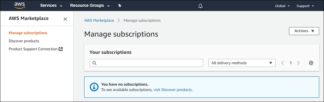
If you have already subscribed to the Cisco CSR 1000v and Cisco vEdge Cloud AMIs within AWS, they will appear here under your active subscriptions and you can skip the remaining steps within this procedure.
Step 6. If you are not subscribed to the Cisco CSR 1000v and Cisco vEdge Cloud AMIs, click on the Discover products link in the navigation panel on the left side of the screen.
This will take you to the Discover Products page within the AWS Marketplace.
Step 7. In the search field at the top of the Discover Products page, type in "Cisco CSR1000v" and click the enter key.
A screen like the figure below should appear.
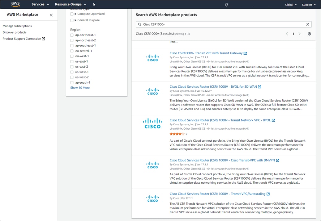
For the Cisco CSR 1000v, there are multiple AMIs which can be selected. For this deployment guide, the Cisco Cloud Services Router (CSR) 1000V – BYOL for SD-WAN AMI was selected.
Step 8. Click the Cisco Cloud Services Router (CSR) 1000V – BYOL for SD-WAN link
This will bring you to the screen where you can subscribe to the AMI. An example is shown in the following figure.
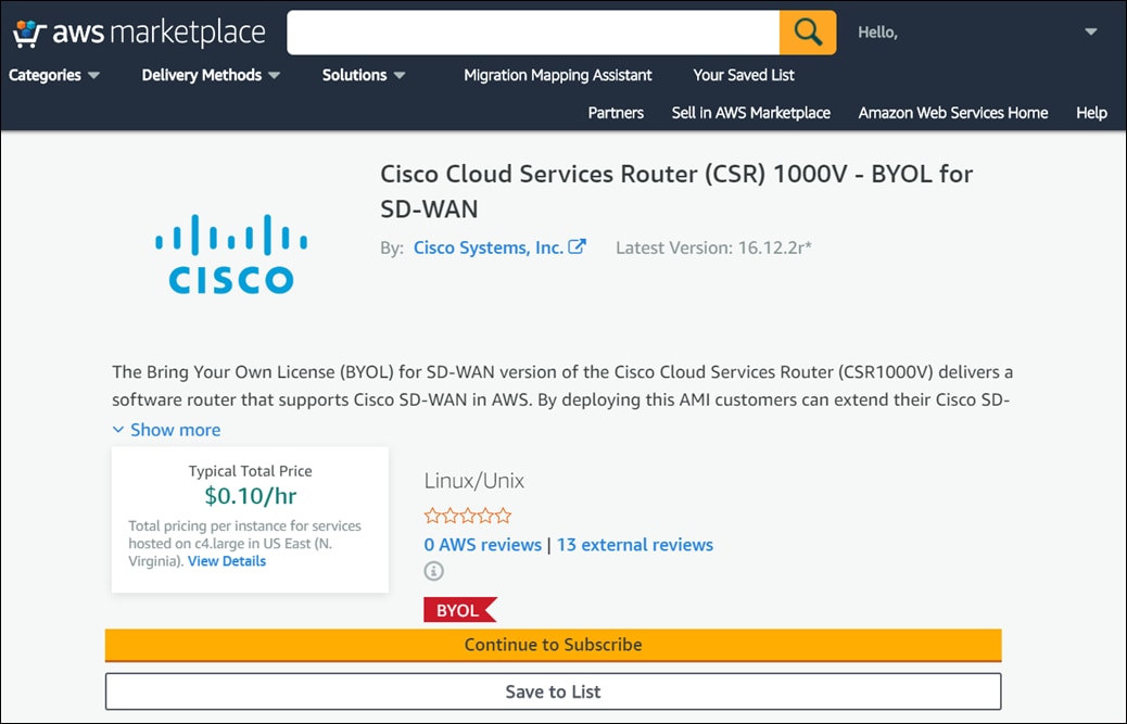
Step 9. Click the Continue to Subscribe button.
If you are already subscribed to the AMI, a screen will appear indicating that you are already subscribed. If you are not already subscribed, you will be taken to a screen which shows the terms and conditions for use of the software. An example is shown in the figure below.
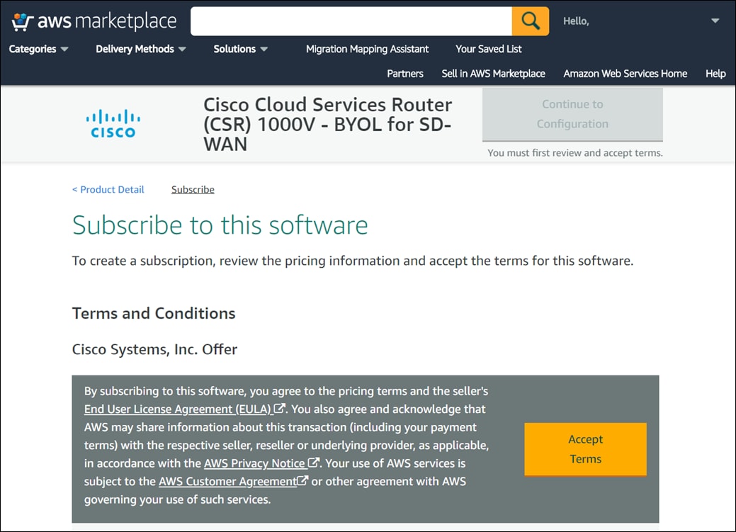
Step 10. Click the Accept Terms button to accept the terms and conditions.
After a few moments, the screen should indicate that you are subscribed to use the Cisco Cloud Services Router (CSR) 1000V – BYOL for SD-WAN AMI. An example is shown in the figure below.
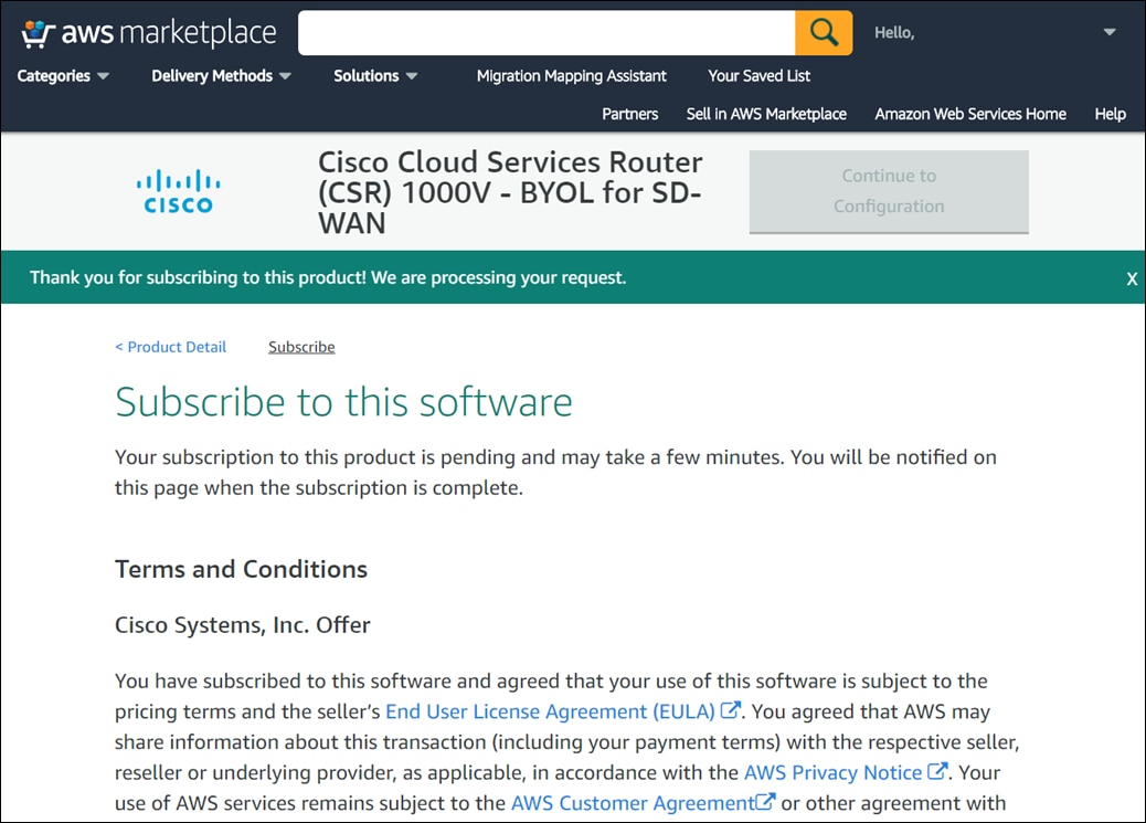
| Tech tip |
| For the subscription of Cisco vEdge Cloud, please follow the same procedures, but instead of “Cisco CSR1000v”, search for “Cisco vEdge Cloud”. |
You do not need to click on the Continue to Configuration button, since Cisco onRamp for IaaS will automatically configure the Cisco SD-WAN Edge Routers when it creates the transit VPC.
Step 11. Logout of the AWS Marketplace by clicking on the arrow in the upper right corner of the screen next to your account name and selecting Sign out.
Procedure 2. Procedure 2: Ensure that at least one user who has administrative privileges has the AWS credentials for your account necessary to make API calls.
Appendix F discusses the procedure for navigating to the AWS security credential section for the userid which will be used by Cisco Cloud onRamp for IaaS to make API calls to AWS. You can verify that an AWS Access Key or IAM Role has already been generated.
Procedure 3. Procedure 3: Verify the AWS resource limits are sufficient within each region which you wish to implement Cisco Cloud onRamp for IaaS.
The AWS limits associated with your account should be sufficient such that the following resources can be created within each region in which you wish to deploy Cisco Cloud onRamp for IaaS:
● 1 VPC, which is required for creating the transit VPC
● 4 Elastic IP addresses per pair of Cisco SD-WAN Edge routers within the transit VPC
● 1 Internet Gateway (IGW) for the transit VPC
● 1 Virtual Private Gateway (VGW) for each host VPC attached to a transit VPC. If the host VPC already has a VGW attached, Cisco Cloud onRamp for IaaS will use this VGW.
● 2 Customer Gateways for each host VPC attached to a transit VPC
● 2 Site-to-Site VPN connections for mapping each host VPC to the Cisco SD-WAN Edge routers within the Transit VPC
Amazon VPC resource limits can be found at the following URL:
https://docs.aws.amazon.com/vpc/latest/userguide/amazon-vpc-limits.html#vpc-limits-gateways
Step 1. From a web browser, navigate to the AWS Management Console at https://console.aws.amazon.com.
Step 2. Enter your Account ID or alias, IAM user name, and Password and click on the Sign In button to login to AWS.
You must use the same AWS account and IAM user name that you will use to generate the AWS Access Key discussed in Appendix G. The AWS Access Key is used to authenticate the AWS API calls from Cisco Cloud onRamp for IaaS that create the transit VPC, instantiate Cisco SD-WAN Edge router instances within the transit VPC, and map host VPCs to the transit VPC.
Step 3. From the AWS Management Console home page, select Services from the menu bar across the top of the screen to display the drop-down menu.
Step 4. From the drop-down menu, select Trusted Advisor under the Management & Governance section.
This will bring up the Trusted Advisor Dashboard.
Step 5. Within the Trusted Advisor Dashboard, click the Service Limits widget at the top of the screen.
This will display only the Service Limits within the Trusted Advisor Dashboard. An example is shown in the figure below.
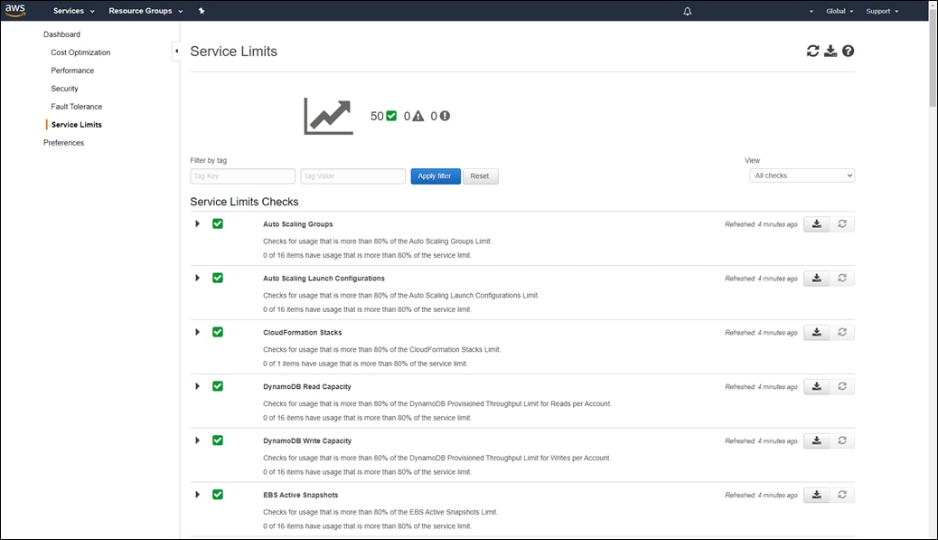
VPC limits
Step 6. Scroll down and click on the arrow next to VPC to expand that section.
This will display the limits for VPCs as well as the number of VPCs currently being used per AWS region. An example is shown in the figure below.
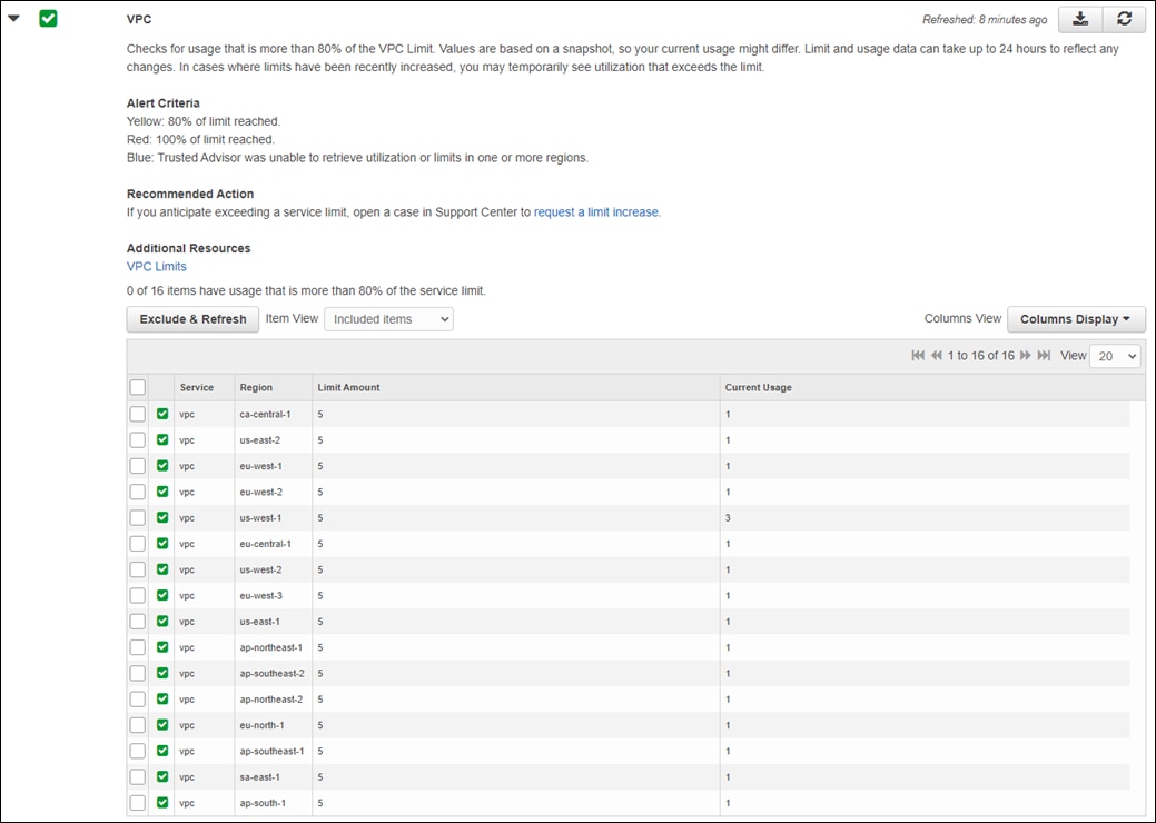
The default limit is five VPCs per AWS region.
Step 7. Verify that your current usage of VPCs is at least one less than your limit amount in each AWS region to which you with to deploy a transit VPC with Cisco Cloud onRamp for IaaS.
Elastic IP Address limits
Step 8. Scroll down and click on the arrow next to VPC Elastic IP Address to expand that section.
This will display the limits for Elastic IP addresses per region as well as the number of Elastic IP addresses currently being used per AWS region. An example is shown in the figure below.
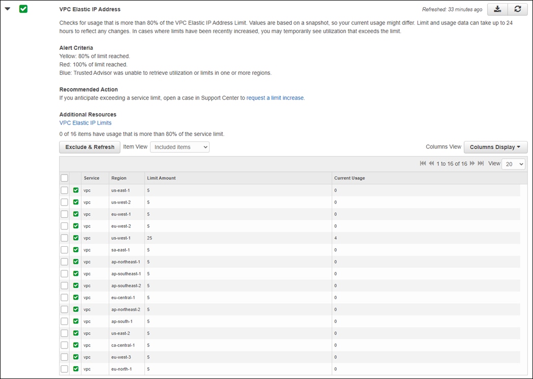
The default limit is five Elastic IP addresses per AWS region.
Step 9. Verify that your current usage of Elastic IP addresses is at least six less than your limit amount in each AWS region to which you with to deploy a transit VPC with Cisco Cloud onRamp for IaaS.
For each pair of Cisco SD-WAN Edge devices instantiated within the transit VPC you will require six Elastic IP addresses. Since the Elastic IP addresses are not actually allocated and used until the pairs of Cisco SD-WAN Edge devices are instantiated, you may want to simply increase the limit of Elastic IP addresses within the AWS region in which you plan to deploy a transit VPC, such that it can support the maximum number Cisco SD-WAN Edge device pairs (4 pairs). In this case the number of Elastic IP Addresses for the AWS region should be increased to a number above 24.
| Tech tip |
| Although the pre-requisites for configuring Cisco Cloud onRamp for IaaS within the Cloud OnRamp Configuration Guide, Cisco IOS XE Release 17 specify six Elastic IP addresses per pair of Cisco SD-WAN Edge devices, only four Elastic IP addresses were allocated and associated per device pair when creating the transit VPCs within this deployment guide. This is because the service VPN has no physical interface in the configuration within this deployment guide. |
An Elastic IP address can be allocated but not associated to any network interface or instance within AWS. In such cases, the Elastic IP address, is available for use by Cisco Cloud onRamp for IaaS, when creating a transit VPC. However, the Elastic IP address will be included in the Current Usage column of the figure above. You may have to navigate to the VPC dashboard by clicking Services > VPC (located under Networking & Content Delivery), and then clicking on Elastic IPs in the navigation panel on the left side of the screen to display the Elastic IP addresses within a given region. Elastic IP addresses which are allocated, but not associated to any network interface or instance within AWS can then be seen, as in the example figure below.
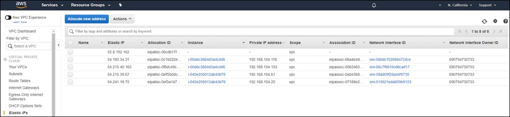
Internet Gateway (IGW) limits
Step 10. Scroll down and click on the arrow next to VPC Internet Gateways to expand that section.
This will display the limits for the number of IGWs, as well as the number of IGWs currently being used per AWS region. An example is shown in the figure below.
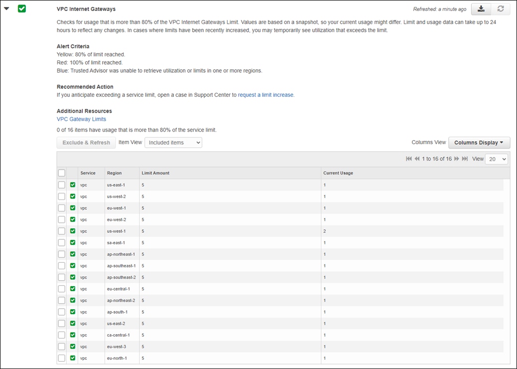
The number of IGWs per region is directly correlated with the number of VPCs per region.
Step 11. Verify that your current usage of IGWs is at least one less than your limit amount in each AWS region to which you with to deploy a transit VPC with Cisco Cloud onRamp for IaaS.
IGWs can be created within a region but not attached to any VPC. Cisco Cloud onRamp will not use an existing IGW that is not attached to any VPC, when deploying a transit VPC.
If you have unused IGWs within a region, you may be able to delete them, rather than requesting an increase in the number of VPCs for the region (which will increase the number of IGWs, since the two values are directly correlated). You may need to navigate to the VPC dashboard by clicking Services > VPC. Click on Internet Gateways in the navigation panel on the left side of the screen to display the IGWs within a given region. IGWs which are created, but not attached to any VPC will have a state of "detached". Select the "detached" VGW, and from the drop-down menu under Actions, select Delete Internet Gateway as in the example figure below. This will delete the unused IGW.
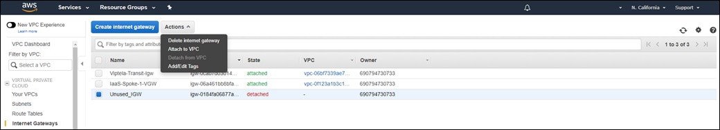
Virtual private gateway (VGW) limits
The Trusted Advisor does not display the number of VGWs per region. The default limit of VGWs per AWS region is five. Only one VGW can be attached to each VPC (host or transit) at a given time within AWS. Cisco Cloud onRamp for IaaS will automatically use an existing VGW attached to a host VPC, when mapping the host VPC to a transit VPC. If host VPC does not have an attached VGW, Cisco Cloud onRamp for IaaS will create a new VGW and attach it to the host VPC.
VGWs can be created within an AWS region, but not attached with any VPC. Cisco Cloud onRamp for IaaS will not attempt to use a VGW which is created but not attached to the host VPC that you will be mapping to the transit VPC.
Step 12. Navigate to the VPC Dashboard by clicking Services > VPC (located under Networking & Content Delivery).
Step 13. Click on Virtual Private Gateways in the navigation panel on the left side of the screen to display the VGWs within a given region.
An example of the existing VGWs within an AWS region is shown in the following figure.
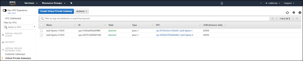
The VPC to which the VGW is attached can be seen in the VPC column. The number of VGWs for the given AWS region is displayed in the upper right corner.
Step 14. You must verify one of the following:
● The host VPCs which you will be mapping to the transit VPC already have an existing VGW. In this case, Cisco Cloud onRamp for IaaS will not have to create any new VGWs and you do not have to worry about the VGW limits per region.
● The host VPCs which you will be mapping to the transit VPC do not have existing VGWs. In this case, you need to verify that your VGW limits per AWS region allow for Cisco Cloud onRamp for IaaS to create and attach one new VGW per host VPC in the region which you plan to deploy the transit VPC.
Customer gateway limits
The Trusted Advisor does not display the number of Customer Gateways per region. The default limit of Customer Gateways per AWS region is 50. Cisco Cloud onRamp for IaaS will automatically create two AWS Customer Gateways for each pair of Cisco SD-WAN Edge routers instantiated with a transit VPC. These Customer Gateways are mapped to the Elastic IP addresses representing the VPN 0 (transport VPN) interfaces of each of the Cisco SD-WAN Edge routers within the transit VPC.
Step 15. Navigate to the VPC Dashboard by clicking Services > VPC (located under Networking & Content Delivery).
Step 16. Click on Customer Gateways in the navigation panel on the left side of the screen to display the Customer Gateways within a given region.
An example of the existing Customer Gateways within an AWS region is shown in the following figure.
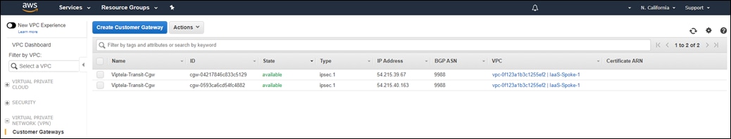
The number of Customer Gateways for the given AWS region is displayed in the upper right corner.
Step 17. Verify that the number of Customer Gateways within each AWS region in which you wish to deploy Cisco Cloud onRamp for IaaS is sufficient such that two additional Customer Gateways can be created for each pair of Cisco SD-WAN Edge devices within each transit VPC you create.
In other words, if you plan on creating only one transit VPC within an AWS region, then Cisco Cloud onRamp for IaaS will need to create two Customer Gateways for each pair of Cisco SD-WAN Edge devices within that transit VPC. You should then verify that the number of existing Customer Gateways within that region is at least two less than the maximum number supported.
However, if you plan on creating two transit VPCs then Cisco Cloud onRamp for IaaS will need to create 2 x 2 = 4 Customer Gateways - two for each of the elastic (public) IP addresses corresponding to each pair of Cisco SD-WAN Edge routers in each transit VPC. You should then verify that the number of existing Customer Gateways within that region is at least four less than the maximum number supported.
Site-to-site VPN connection limits
The Trusted Advisor does not display the number of Site-to-Site VPN connections. The default limit of Site-to-Site VPN connections per AWS region is 50. The default limit of Site-to-Site VPN connections per VPC (technically per VGW since there is one VGW per VPC) is 10. Since Cisco Cloud onRamp for IaaS may use an existing VGW within a host VPC, you will have to check for both limits.
Step 18. Navigate to the VPC Dashboard by clicking Services > VPC.
Step 19. Click on Site-to-Site VPN Connections in the navigation panel on the left side of the screen to display the Site-to-Site VPN connections within a given region.
An example of the existing Site-to-Site VPN connections within an AWS region is shown in the following figure.
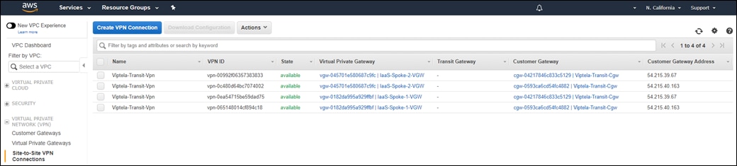
Cisco Cloud onRamp for IaaS will automatically create two Site-to-Site VPN connections within each host VPC which is mapped to a transit VPC. Cisco Cloud onRamp for IaaS will not attempt to use any existing Site-to-Site VPN connections attached to a VGW within a host VPC, when mapping the host VPC to a transit VPC. Each host VPC is attached to only one pair of Cisco SD-WAN Edge routers within a transit VPC if the transit VPC has multiple pairs of Cisco SD-WAN Edge routers.
Step 20. Verify that the number of Site-to-Site VPN connections within each AWS region in which you wish to deploy Cisco Cloud onRamp for IaaS is sufficient such that two additional Site-to-Site VPN connections can be created per host VPC which will be mapped to the transit VPC.
In other words, if you plan on mapping two host VPCs to the transit VPC, then Cisco Cloud onRamp for IaaS will need to create 2 x 2 = 4 Site-to-Site VPN connections within that AWS region. You should then verify that the number of existing Site-to-Site VPN connections within that region is at least four less than the maximum number supported.
Step 21. Verify that the number of existing Site-to-Site VPN connections attached to a given VGW in any host VPC which you plan on mapping to a transit VPC is two less than the maximum number of Site-to-Site VPN connections supported for the VGW.
Security group limits
The Trusted Advisor does not display the number of Security Groups used per region. The default limit of Security Groups per AWS region is 2500. You will have to verify that the number of Security Groups configured within the region in which you wish to deploy a transit VPC is one less than the maximum supported.
Step 22. Navigate to the VPC Dashboard by clicking Services > VPC.
Step 23. Click on Security Groups in the navigation panel on the left side of the screen to display the Security Groups within a given region.
An example of the existing Security Groups within an AWS region is shown in the following figure.
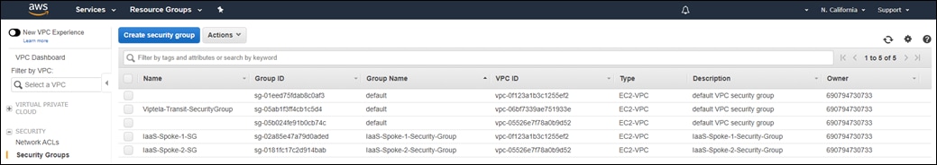
Cisco Cloud onRamp for IaaS will automatically create a Security Group named Viptela-Transit-SecurityGroup within the AWS region in which a transit VPC is created.
Step 24. Verify that the number of Security Groups within each AWS region in which you wish to deploy a transit VPC is sufficient such that one additional Security Group can be created.
Procedure 4. Increasing service limits
If any of the AWS prerequisites discussed in the procedure above are not met, you will need to request one or more limit increases from Amazon.
Step 1. Within AWS, navigate to the AWS Support Center at https://console.aws.com/support/home.
Step 2. From the AWS Support Center home page click on the Create case button.
This will take you to a screen to create an AWS case.
Step 3. Click on the Service limit increase widget.
Additional fields will appear as shown in the figure below.
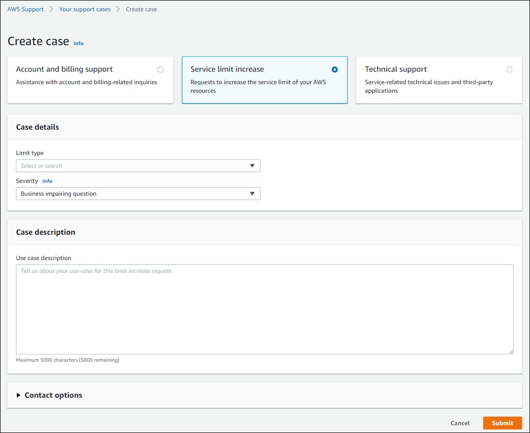
Step 4. From the drop-down menu next to Limit Type, select VPC.
Step 5. Within the widget named Request 1, select the region in which you want to increase a VPC limit from the drop-down menu next to Region.
Step 6. From the drop-down menu next to Limit, select the specific limit you want to increase.
The limits that apply to the features discussed within deployment guide are as follows:
● VPCs per Region
● VPC Elastic IP Address Limit
● Virtual Private Gateways per Region
● VPN Connections per VPC
● VPN Connections per Region
Step 7. If you have more than one limit request, you can bundle them together in one case, by clicking on the Add another request button, to bring up another request widget.
Step 8. When you are done adding requests, select the Preferred Contact Language from the drop-down menu, the Contact methods (web, chat, or phone), and fill in the necessary information for Amazon to contact you if necessary about your case.
Step 9. Click the Submit button to submit the case.
Amazon will contact you if anything within your request needs clarification. Otherwise your request will be fulfilled, and the limits increased.
Appendix F: Creating an AWS IAM Role
Cisco Cloud OnRamp for IaaS for programmatically creates a transit VPC, instantiates Cisco SD-WAN Edge router instances within the transit VPC, and maps host VPCs to the transit VPC - all through AWS API calls. For this deployment guide, an IAM role must be generated to authenticate the userid that executes the API calls.
This section shows how to create a very basic IAM role with an ExternalID string for authentication when creating AWS cloud instances within Cisco Cloud onRamp for IaaS.
This deployment guide assumes you already have an AWS account with the necessary access privileges.
Procedure 1. Navigate to the security credentials within your account
This section discusses the procedure for navigating to the AWS security credential section for the IAM role which will be used by Cisco Cloud onRamp for IaaS to make API calls to AWS.
Step 1. Login to the AWS console at https://console.aws.amazon.com.
Step 2. Enter your AWS Account ID, IAM username, and Password.
Step 3. From the AWS console home page, select Services from the menu bar across the top of the screen to display the drop-down menu.
Step 4. From the drop-down menu, select IAM under the Security, Identity & Compliance section.
This will bring up the IAM Dashboard.
Step 5. From the IAM Dashboard select Access Management > Roles from the navigation panel on the left side of the screen.
This will bring up the existing roles for your account. There may be multiple roles associated with your AWS account.
Step 6. Click the Create role button to bring up the Create role screen.
An example is shown in the following figure.
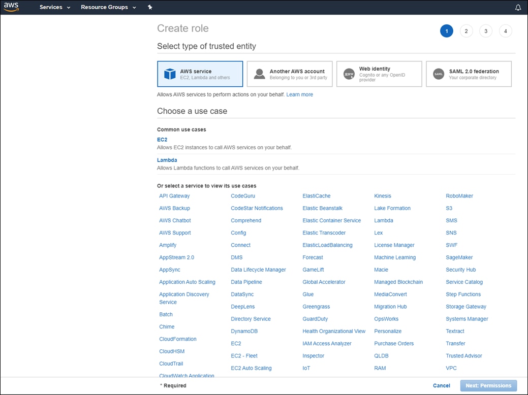
Step 7. Click on the Another AWS account button.
The screen will change to the following.
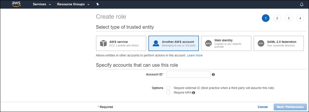
Step 8. If the vManage NMS is hosted by Cisco on AWS and trusts the AWS account, 200235630647, that hosts the vManage NMS, enter the value 200235630647 in the Account ID field and click Next: Permissions. Otherwise, if the vManage NMS is locally hosted, enter your AWS account in the Account ID field and click Next: Permissions.
For this deployment guide, the vManage NMS was hosted by Cisco on AWS, so the account 200235630647 was entered.
This will take you to the Attach Permissions Policies screen, as shown in the figure below.
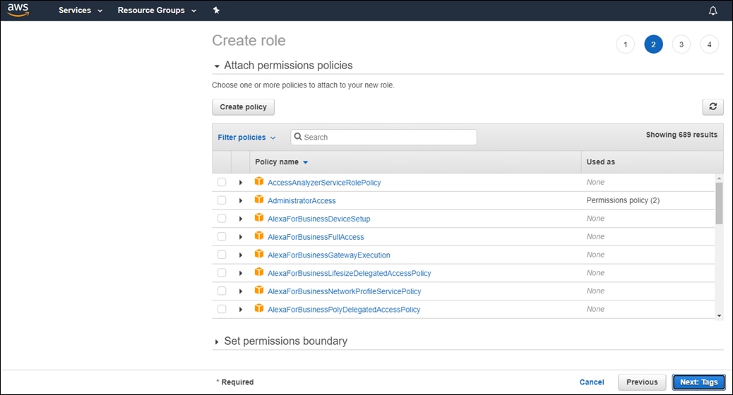
Step 9. In the list of policies within the Attach Permissions Policies screen scroll down and select the following two policies – AmazonEC2FullAccess and AmazonVPCFullAccess - and click on Next: Tags.
Step 10. Click Next: Review to continue.
Step 11. In the Role name field of the Review screen, give the IAM Role a name and click Create role.
For this deployment guide, the Role name of saville_onRampIaaS was configured. An example is shown in the following figure.
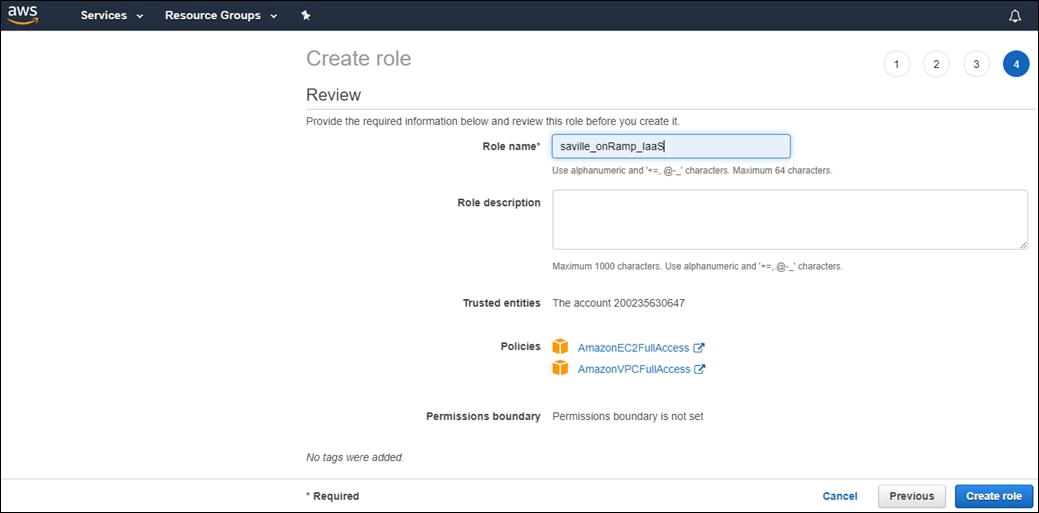
This will take you back to the IAM Roles screen.
Step 12. Scroll down the list of Roles until you find the new Role you just entered and click on it.
This will bring up a Summary screen similar to the following.
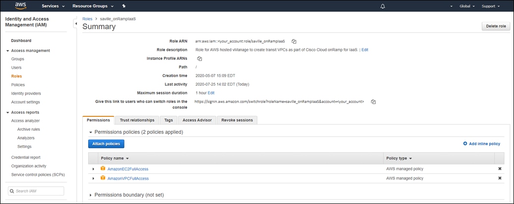
The Role ARN is listed at the top of the Summary screen. This is the value you enter in the Cisco Cloud onRamp for IaaS when you create a new AWS cloud instance using an IAM Role.
Step 13. In order to create an External ID, click on the Trust relationships tab and then click Edit Trust Relationship.
Step 14. Within the Policy Document, edit the JSON text to add the following under the “Conditions”: key.
"StringEquals": {
"sts:ExternalId": "Your_External_ID_String"
}
Where “Your_External_ID_String” is your External ID. This is the External ID value you enter in the Cisco Cloud onRamp for IaaS when you create a new AWS cloud instance using an IAM Role.
The output should look similar to the following figure.
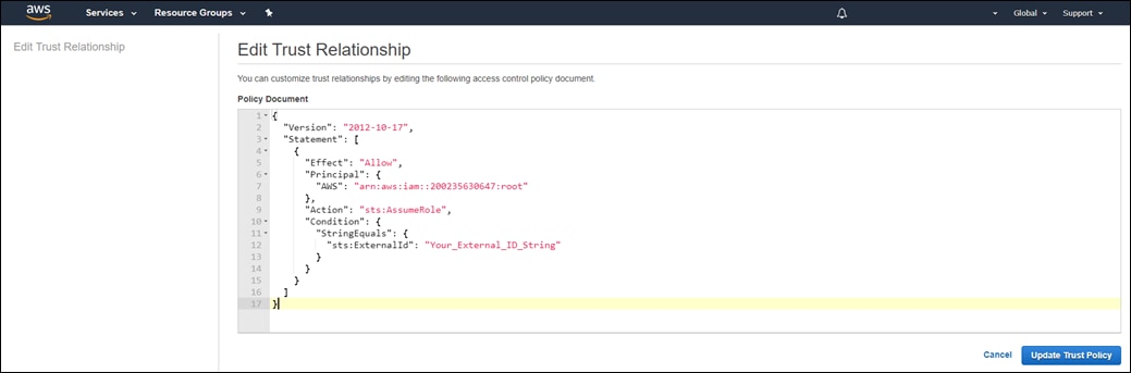
Step 15. Click Update Trust Policy to update the IAM Role with the External ID and return to the Summary screen.
This example has shown how to create a very basic IAM Role for use with Cisco Cloud onRamp for IaaS. Please ensure that any AWS credentials (Userid/Access Keys or IAM Roles) you create for working with Cisco Cloud onRamp for IaaS comply with any security policies set forth and enforced by security operations within your organization.
Appendix G: Generating an AWS SSH key pair
A public-private SSH key pair is used to access AWS EC2 instances, including the Cisco SD-WAN Edge routers created by Cisco Cloud onRamp within the transit VPC. You must either have an SSH key pair available to use - meaning you have downloaded and saved the private key when you generated the key pair - or you must generate a new key pair.
This deployment guide assumes you already have an AWS account with the necessary access privileges.
Procedure 1. Navigate to key pairs within AWS
This section discusses the procedure for navigating to the AWS key pairs screen within the AWS region in which you wish to create a transit VPC. You can verify if you have an existing SSH key pair which can be used to access the Cisco SD-WAN Edge routers which will be created in the transit VPC by Cisco Cloud onRamp.
Step 1. Login to the AWS console at https://console.aws.amazon.com.
Step 2. Enter your AWS Account ID, IAM username, and Password.
Step 3. From the AWS console home page, select Services from the menu bar across the top of the screen to display the drop-down menu.
Step 4. From the drop-down menu, select EC2 under the Compute section.
This will bring up the EC2 Dashboard.
Step 5. From the EC2 Dashboard select Key Pairs from the navigation panel on the left side of the screen.
This will bring up your existing key pairs for the AWS region. If you need to change the AWS region, select the region from the drop-down menu in the upper right corner of the screen. An example of the Key Pairs screen is shown in the figure below.
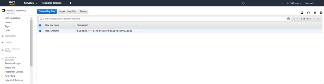
If you have downloaded and saved the private key associated with any of the key pairs which appear, you can use that key pair. Otherwise, you will need to generate a new key pair.
Procedure 2. Create a new key pair
Step 1. Click the Create Key Pair button.
A pop-up window will appear, asking you to provide a key pair name.
Step 2. Enter a key pair name and click on the Create button.
This will automatically download the private key file to your device, with a file name corresponding to the name of your key pair, and a file extension of .pem. For example, this deployment guide uses a key pair named IaaS_onRamp when creating the transit VPC. The key pair file automatically downloaded when the SSH key pair was generated is named IaaS_onRamp.pem. Store this file securely on your device.
AMI Amazon machine image
ASN Autonomous system number
AWS Amazon Web Services
CGW AWS customer gateway
EC2 AWS Elastic Compute Cloud
IaaS Infrastructure as a Service
IAM AWS Identity and Management
IGW AWS internet gateway
SEN SD-WAN Secure Extensible Network
TGW AWS Transit gateway
VGW AWS virtual private gateway
VPC Virtual Private Cloud
VPN Virtual Private Network
WAN Wide Area Network
For comments and suggestions about this guide and related guides, join the discussion on Cisco Community at https://cs.co/en-cvds.