InfiniBand Concepts
Available Languages
Table Of Contents
Understanding the Subnet Manager
Understanding Subnet Manager Routing Terms
Minimum Contention, Shortest Path, and Load Balancing Algorithm
Deterministic Source-Based Routing Algorithm
Configuring Your Network For Optimal Routing
Hexadecimal to Binary Conversions
Examples of Valid P_Key Values
Understanding How P_Keys are Saved
InfiniBand Concepts
These topics describe InfiniBand concepts:
Understanding InfiniBand
InfiniBand is a high-speed hardware, specialized protocols, high-density serial interconnection that increases CPU utilization, decreases latency, and eases the management problems of data centers. The term "InfiniBand" refers to the entire hardware, communication, and management infrastructure. This technology increases the communication speed between the following:
•
CPUs
•
•
Operations of the InfiniBand Architecture are managed by the Subnet Manager. These topics provide further details:
•
InfiniBand Components
One or more of the following hardware components may be used to maximize your server network:
•
•
•
•
Protocols
InfiniBand requires a new set of protocols. All of the necessary protocol drivers are included with the server switch. These protocols include:
•
•
IPoIB
The IP over InfiniBand (IPoIB) link driver provides standardized IP encapsulation over InfiniBand fabrics. IPoIB can transparently use IP over InfiniBand technology, which is similar to the way that IP runs over Ethernet.
You can use the IPoIB driver to perform an address resolution and manage the multicast membership.
SDP
The Sockets Direct Protocol (SDP) is a transparent protocol used on InfiniBand networks to allow sockets-based applications to take advantage of the RDMA performance over an InfiniBand network. SDP reduces the amount of software running inside a process context. The zero-copy SDP support enables databases, application servers, and CPUs to operate more efficiently because the databases spend less time waiting for work, the application servers spend less time waiting for responses, and the CPUs have more cycles free for other work.
SRP
The SCSI RDMA Protocol (SRP) is an upper-layer storage protocol for InfiniBand that runs SCSI commands across RDMA-capable networks for InfiniBand hosts to communicate with Fibre Channel storage devices. This protocol allows InfiniBand hosts to natively send SCSI commands as if the storage was directly attached.
The SRP protocol uses an RDMA communication service that provides communication between pairs of consumers; it uses messages for control information and RDMA operations for data transfers.
The SRP protocol is used only if you have a Fibre Channel Gateway installed in your InfiniBand system.
uDAPL
The user Direct Access Programming Library (uDAPL) is a standardized user mode API that natively supports InfiniBand fabrics. uDAPL performs name-to-address translations, establishes connections, and transfers data reliably. The primary responsibilities of uDAPL are connection management and low latency data transfer and completion.
Architectural Elements
The following structures serve as foundational elements of InfiniBand architecture:
•
RDMA
InfiniBand uses RDMA technology. RDMA allows one computer to place information directly into the memory of another computer. RDMA allows user space applications to directly access hardware and zero-copy data movement.
A combination of hardware and software allows user space applications to read and write the memory of a remote system without kernel intervention or unnecessary data copies. This feature results in lower CPU utilization per I/O operation and more efficient use of machine resources because applications place most of the messaging overheads upon the InfiniBand high-speed network hardware.
Queue Pairs
The queue pair (QP) is one of the primary architectural elements of InfiniBand. In InfiniBand, communication occurs between queue pairs, instead of between ports.
A queue pair is an addressable entity that consists of two work queues: a Send work queue and a Receive work queue. The Channel Adapter hardware arbitrates communication by multiplexing access to the send queue or demultiplexing messages on the receive queue.

Note
A work queue provides a consumer with the ability to queue up a set of instructions that are executed by the Channel Adapter. There are two types of work queues: Send work queues (outbound) and a receive work queues (inbound). Together these work queues create a queue pair.
A connection is made by linking a local queue pair to a remote queue pair. Applications do not share queue pairs; once you set them up, you can manage them at the application level without incurring the overhead of system calls.
Send and receive work queues have these characteristics:
•
•
•
•
Queue pairs have these characteristics:
•
•
•
The queue pair is the mechanism by which you define quality of service, system protection, error detection and response, and allowable services.
Each queue pair is independently configured for a particular type of service. These service types provide different levels of service and different error-recovery characteristics as follows:
•
•
•
•
Once the fabric connections are discovered, queue pairs and protection domains are established, the type and quality of service are defined for each queue pair, and the fabric operates reliably and securely at full QoS without impacting system hardware or software resources.
Understanding the Subnet Manager
The Subnet Manager configures and maintains fabric operations. There can be multiple Subnet Managers but only one master. The Subnet Manager is the central repository of all information that is required to set up and bring up the InfiniBand fabric.
The master Subnet Manager does the following:
•
•
•
–
–
–
•
•
•
These topics provide additional details:
Subnet Management Agents
Subnet Manager Agents are part of the Subnet Manager. A Subnet Manager Agent is provided with each node and processes packets from the Subnet Manager.
If a Subnet Manager is elected master, all of its components, including Subnet Agent, are implicitly elected master. If a Subnet Manager ceases to be the master, all of its components cease responding to messages from clients.
Subnet Manager Hot Standby
The master and slave Subnet Managers can be synchronized so that the information in the master is carried over to the slave if a failover occurs. See the "Enabling Subnet Manager Database Synchronization" section to configure the hot-standby Subnet Manager.
The hot standby/database synchronization feature is used to synchronize the databases between Subnet Managers running on separate chassis.
The Subnet Manager maintains a database in the volatile memory of the master Subnet Manager. Database synchronization is accomplished in two stages:
•
•
A standby Subnet Manager can become the master in any of these situations:
•
•
•
The following occurs in the event of a failure:
•
•
•
•
•
Subnet Manager Routing
There are two different concepts associated with InfiniBand routing:
•
•
Note
Internal switch routing can be configured to provide the highest performance in passing traffic and to minimize the threat of congestion within the switch.
The routing process is as follows:
1.
2.
3.
4.
5.
These topics provide additional details:
•
•
•
•
Multiple Paths
The Subnet Manager allows you to define the Local Identifier Mask Control (LMC) value per subnet. The default value of the LMC is 0. By default, only one Local Identifier (LID) is assigned to each host port.
Once the LMC value has been assigned, the Subnet Manager will route different paths for each LID associated with the same host port. The result of these paths is based on the applied routing algorithm.
Understanding Subnet Manager Routing Terms
The following terms are important to understand before distinguishing the various types of algorithms that the Subnet Manager uses for routing:
•
–
–
•
Minimum Contention, Shortest Path, and Load Balancing Algorithm
The Minimum Contention, Shortest Path, and Load Balancing algorithm is used by default to route between the switch elements and between the internal InfiniBand switch chips within each switch element.
The following process shows how the algorithm makes the calculation:
1.
2.
a.
b.
c.
Deterministic Source-Based Routing Algorithm
The Deterministic Source Based Routing algorithm is used in some high-performance computing environments where the requirements may need to be more stringently defined. An administrator can identify the exact route that a given port and LID takes for traversing through the network.
Currently, only the internal routing for the Cisco SFS 7008 (a 96-port switch) supports this routing scheme. See the Cisco SFS 7008 Hardware Guide, or contact Cisco TAC for more information.
Configuring Your Network For Optimal Routing
For optimal routing, we recommend that you follow these steps:
•
•
We recommend that InfiniBand switch elements be connected so that all paths between any pair of switch elements are the same distance (same number of hops), if possible. This process enables you to obtain the optimal paths using the default tolerance of 0. If the paths have different lengths, then the tolerance value will need to be determined.
The Subnet Manager Routing Algorithm selects the first best path that it finds. If multiple paths with the same properties are available, then the first of these paths found is the one that is selected. It is possible to set up the cabling between switch elements to force the algorithm to prioritize certain paths. Depending on the network requirements, the prioritized paths can either be concentrated on a particular switch element or spread across multiple switch elements to improve fault tolerance.
Understanding Partitions
A partition defines a set of InfiniBand nodes that are permitted to communicate with one another. Partitions do the following:
•
•
•
Note
These topics provide details:
•
How Partitions Work
A partition defines a set of InfiniBand nodes that are permitted to communicate with one another. Each node may be part of multiple partitions so that a system administrator can define overlapping partitions as the situation requires. Normal data packets carry a 16-bit P_Key, or partition key, that defines a unique partition. The Subnet Manager configures the channel adaptor for each node with its set of P_Keys. When a packet arrives at a node, the channel adapter checks that the packet's P_Key is valid based on the Subnet Manager's configuration. Packets with invalid P_Keys are discarded. P_Key validation prevents a server from communicating with another server outside of its partition.
InfiniBand partitions are comparable to hardware-enforced security features of conventional I/O networking technologies, such as Ethernet VLANs and Fibre Channel zones.
Partition Members
Without members, a partition does not have meaning to the system. Ports are added to the partition and become members of that partition. Each port may be part of multiple partitions so that you can define overlapping partitions as the situation requires.
At the time a port member is added to the partition, you must decide whether that particular port will have full or limited membership.
Membership Types
A partition contains a group of members, but different types of members can exist within a single partition. Partition membership allows even further control because it defines communication within the members of that group, not just outside of it.
There are two types of partition memberships: full membership and limited membership. A full-membership partition member can communicate with all other partition members including other full members and limited members. A limited-membership partition member cannot communicate with other limited-membership partition members. However, a limited partition member can communicate with a full member.
About the Default Partition
The Subnet Manager automatically configures a default partition, which is always p_key ff:ff.
The default partition controls all connected ports, and by default, everything is a full member of the default partition. The default p_key cannot be altered or deleted as it is the controlling mechanism that manages the configuration of all the partitions.
Selecting a P_Key Value
For a list of acceptable P_Key values, see Table A-2.
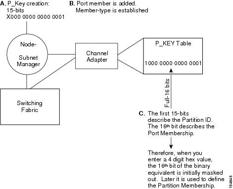
Upon creation, the p_key value (see Figure A-1) is technically a 15-bit number. However, after the p_key is created and the port(s) membership type has been established, the entire value becomes 16 bits. The most significant bit (MSB) displays the type of membership (0 = Limited member, 1 = Full member).
When assigning a p_key value, you need to choose four hexadecimal numbers. However, because of the way that the 16th bit is used, only certain numbers can be used for the most significant digit. Do not attempt to create two P_Keys differing only in the most significant bit of their 16-bit numbers. The system views them as the same P-Key. For example, 0 #:# # is the same P-Key as 8#:# #.
Figure A-1 Partition Keys
These topics provide further help in selecting a P_Key value:
•
•
Hexadecimal to Binary Conversions
Table A-1 is provided to assist in the creation of P_keys. When creating the partition p_key, enter a hexadecimal value that is the equivalent of 16 bits in binary. For example, enter 80:00 (hex) to be 10000000000000000 (binary). The default partition (which cannot be altered) is 7f:ff.
Table A-1 Binary Conversions
0
0000
1
0001
2
0010
3
0011
4
0100
5
0101
6
0110
7
0111
8
1000
9
1001
A
1010
B
1011
C
1100
D
1101
E
1110
F
1111
Examples of Valid P_Key Values
You can choose your own p_key values, or you can choose your values from the list in Table A-2.
Table A-2 Valid P_Key Numbers
00:01
00:11
00:02
00:12
00:03
00:13
00:04
00:14
00:05
00:15
00:06
00:16
00:07
00:17
00:08
00:18
00:09
00:19
00:10
00:20
Understanding How P_Keys are Saved
Partition information is saved by the master Subnet Manager. If db-sync is enabled, the master Subnet Manager synchronizes P_key information to standby Subnet Managers (currently, only one standby manager is allowed). A synchronized standby retains the information from the master.
If you configure only one InfiniBand switch, it is automatically the master, and the partition configuration is saved persistently on the switch. See the "Enabling Subnet Manager Database Synchronization" section for details.
 Feedback