Cisco Physical Security Multiservices Platform Series User Guide
Bias-Free Language
The documentation set for this product strives to use bias-free language. For the purposes of this documentation set, bias-free is defined as language that does not imply discrimination based on age, disability, gender, racial identity, ethnic identity, sexual orientation, socioeconomic status, and intersectionality. Exceptions may be present in the documentation due to language that is hardcoded in the user interfaces of the product software, language used based on RFP documentation, or language that is used by a referenced third-party product. Learn more about how Cisco is using Inclusive Language.
- Updated:
- January 6, 2011
Chapter: Setting Up the Chassis
Setting Up and Maintaining the Multiservices Platform Series Device
This chapter describes how to perform a variety of set up and hardware maintenance procedures for the the Multiservices Platform Series device.
Setting up a device includes unpacking it, mounting it in a rack, installing hard drives if needed, and connecting it to power, the network, and external devices.
Maintenance procedures that you may need to perform for a Multiservices Platform Series device include replacing a fan or power supply and checking air flow around the device.
This chapter includes these sections:
•![]() Setting up a Multiservices Platform Series Device
Setting up a Multiservices Platform Series Device
•![]() Multiservices Platform Series Maintenance Operations
Multiservices Platform Series Maintenance Operations
Setting up a Multiservices Platform Series Device
When you receive a Multiservices Platform Series device, you should perform the following general set-up steps in this order:
1. ![]() Unpack the device and verify the package contents.
Unpack the device and verify the package contents.
2. ![]() Mount the device in a rack.
Mount the device in a rack.
3. ![]() Install hard drive, if necessary
Install hard drive, if necessary
4. ![]() Connect the device to power, the network and external devices.
Connect the device to power, the network and external devices.
Then, see your physical security application documentation for information about installing the application and configuring the device.
For detailed information, see the following sections:
•![]() Unpacking the Multiservices Platform Series Device
Unpacking the Multiservices Platform Series Device
•![]() Mounting the Multiservices Platform Series Device in a Rack
Mounting the Multiservices Platform Series Device in a Rack
•![]() Connecting to Power, the Network, and External Devices
Connecting to Power, the Network, and External Devices
Unpacking the Multiservices Platform Series Device
A Multiservices Platform Series device ships in one or two boxes, depending on the model and number of hard drives that your ordered:
•![]() 1-RU model—Ships in one box that contains the chassis with hard drives preinstalled.
1-RU model—Ships in one box that contains the chassis with hard drives preinstalled.
•![]() 2-RU model—Ships in two boxes. One box contains the chassis and one box contains from 4 to 12 hard drives.
2-RU model—Ships in two boxes. One box contains the chassis and one box contains from 4 to 12 hard drives.
To unpack the Multiservices Platform Series device, follow these steps:
Procedure
Step 1 ![]() If your shipment includes two boxes, make sure that the serial number that is printed on the shipping label on each box is the same.
If your shipment includes two boxes, make sure that the serial number that is printed on the shipping label on each box is the same.

Step 2 ![]() Carefully open each shipping box and remove its contents.
Carefully open each shipping box and remove its contents.
Step 3 ![]() Make sure that the box in which the chassis shipped includes these items:
Make sure that the box in which the chassis shipped includes these items:
•![]() Rail assemblies for rack mounting
Rail assemblies for rack mounting
•![]() Operating system license and activation packet (if applicable)
Operating system license and activation packet (if applicable)
•![]() Envelope that contains the following:
Envelope that contains the following:
–![]() Getting Started with Cisco Video Surveillance Manager Products
Getting Started with Cisco Video Surveillance Manager Products
–![]() Recovery disk
Recovery disk
–![]() End user license and warranty information disk
End user license and warranty information disk
–![]() One or two power cables (if ordered).
One or two power cables (if ordered).
–![]() Screws and washers for rack mounting
Screws and washers for rack mounting
Mounting the Multiservices Platform Series Device in a Rack
The Multiservices Platform Series device is designed to be installed in a standard 19-inch rack. The server ships with a pair of rail assemblies.
This section describes how to rack mount the Multiservices Platform Series device. It includes these topics:

Note ![]() Some figures in this chapter show sample hardware and devices. The procedures are similar for all models.
Some figures in this chapter show sample hardware and devices. The procedures are similar for all models.
Preparing for Rack Mounting
Before you install the Multiservices Platform Series device in a rack, review the following guidelines:
Choosing a Location
•![]() Leave enough clearance in front of the rack to enable you to open its front door completely (approximately 25 inches).
Leave enough clearance in front of the rack to enable you to open its front door completely (approximately 25 inches).
•![]() Leave approximately 30 inches of clearance in back of the rack to allow for sufficient air flow and ease of servicing.
Leave approximately 30 inches of clearance in back of the rack to allow for sufficient air flow and ease of servicing.
•![]() The Multiservices Platform Series device is intended for installation in a restricted access location, such as a dedicated equipment room or service closet.
The Multiservices Platform Series device is intended for installation in a restricted access location, such as a dedicated equipment room or service closet.
Rack Precautions
•![]() Ensure that the leveling jacks on the bottom of the rack are extended to the floor with the full weight of the rack resting on them.
Ensure that the leveling jacks on the bottom of the rack are extended to the floor with the full weight of the rack resting on them.
•![]() In a single rack installation, attach stabilizers to the rack.
In a single rack installation, attach stabilizers to the rack.
•![]() In a multiple rack installation, couple the racks to each other.
In a multiple rack installation, couple the racks to each other.
•![]() Make sure that the rack is stable before extending a component from the rack.
Make sure that the rack is stable before extending a component from the rack.
•![]() Extend only one component from a rack at a time. Extending two or more components may cause the rack to become unstable.
Extend only one component from a rack at a time. Extending two or more components may cause the rack to become unstable.
General Precautions
•![]() Review the electrical and general safety precautions that come with the components that you add to your chassis.
Review the electrical and general safety precautions that come with the components that you add to your chassis.
•![]() Determine the placement of each component in the rack before you install the rails.
Determine the placement of each component in the rack before you install the rails.
•![]() Install the heaviest components on the bottom of the rack first, then work up.
Install the heaviest components on the bottom of the rack first, then work up.
•![]() Use a regulating uninterruptible power supply (UPS) to protect a device from power surges and voltage spikes and to keep the device operating if a power failure occurs.
Use a regulating uninterruptible power supply (UPS) to protect a device from power surges and voltage spikes and to keep the device operating if a power failure occurs.
•![]() Close the front door of the rack and all panels and components on the servers when not servicing them to maintain proper cooling.
Close the front door of the rack and all panels and components on the servers when not servicing them to maintain proper cooling.
Rack Mounting Considerations
•![]() Make sure to install the Multiservices Platform Series device in an environment that is within the rated operating temperature and humidity range (see "System Specifications"). If the Multiservices Platform Series device is installed in a closed or multi-unit rack assembly, be aware that the ambient operating temperature of the rack environment may be greater than the ambient temperature of the room.
Make sure to install the Multiservices Platform Series device in an environment that is within the rated operating temperature and humidity range (see "System Specifications"). If the Multiservices Platform Series device is installed in a closed or multi-unit rack assembly, be aware that the ambient operating temperature of the rack environment may be greater than the ambient temperature of the room.
•![]() Make sure that there is sufficient air flow for safe operation of the Multiservices Platform Series device.
Make sure that there is sufficient air flow for safe operation of the Multiservices Platform Series device.
•![]() The Multiservices Platform Series device should be mounted in a rack so that a hazardous condition does not arise due to uneven mechanical loading.
The Multiservices Platform Series device should be mounted in a rack so that a hazardous condition does not arise due to uneven mechanical loading.
•![]() Consider the connection of equipment to the power supply circuitry and the effect that possible overloading of circuits may have on overcurrent protection and power supply wiring. Consider equipment nameplate ratings when addressing this issue.
Consider the connection of equipment to the power supply circuitry and the effect that possible overloading of circuits may have on overcurrent protection and power supply wiring. Consider equipment nameplate ratings when addressing this issue.
•![]() Maintain a reliable ground. The rack itself should be grounded. Pay particular attention to power supply connections other than direct connections to the branch circuit (for example, power strips).
Maintain a reliable ground. The rack itself should be grounded. Pay particular attention to power supply connections other than direct connections to the branch circuit (for example, power strips).
Rack Mounting
This section describes how to install the Multiservices Platform Series device in a rack by using the quick release mounting system. This system provides a quick, convenient, and secure method for rack mounting the Multiservices Platform Series device.
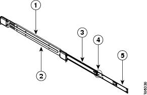
The Multiservices Platform Series device includes two rail assemblies. One is designed for the left side of the chassis and one is designed for the right side. Each rail assembly consists of an inner chassis rail that attaches to the chassis, an outer rail that attaches to a rack, and a middle rail that extends from the outer rail. Each inner rail includes a locking tab, which prevents the server from unintentionally coming completely out of the rack when you pull it out for servicing or access.
Installing the Multiservices Platform Series device in a rack by using the quick release mounting system involves these steps. The following sections describe each step in detail.
•![]() Installing Square Hole to Round Hole Adapters (Optional)
Installing Square Hole to Round Hole Adapters (Optional)
•![]() Attaching the Inner Rails to the Multiservices Platform Series Device
Attaching the Inner Rails to the Multiservices Platform Series Device
•![]() Attaching the Outer Rails to a Rack
Attaching the Outer Rails to a Rack
•![]() Placing the Multiservices Platform Series Device in the Rack
Placing the Multiservices Platform Series Device in the Rack
Before you attach the rack rails, see Figure 2-1 to become familiar with the rail components assembly. This figure shows the left rail assembly, which attaches to the left side of the Multiservices Platform Series device.
Figure 2-1 Identifying the Rail Assembly Components (Left Rail Assembly Shown)
|
|
Outer rail |
|
Inner rail locking tab |
|
|
Outward-facing side of outer rail |
|
Inner rail |
|
|
Middle rail |
Note ![]() There are a variety of racks available. The procedure for your rack may be slightly different than the following instructions. Refer to the installation instructions for your rack for additional information.
There are a variety of racks available. The procedure for your rack may be slightly different than the following instructions. Refer to the installation instructions for your rack for additional information.
Installing Square Hole to Round Hole Adapters (Optional)
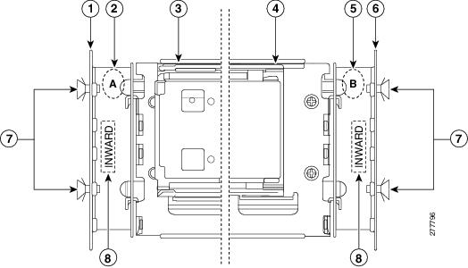
The quick release mounting system on the Multiservices Platform Series 2-RU model is designed for racks with square holes. If you want to use this system with a round hole rack or a threaded hole rack (with thread size M5 or larger), you can do so by using the square hole to round hole adapter set. This set includes four brackets, which attach to the front and rear of the right and left rack rails and provide square holes to which you can attach the quick release rack rails.
To install the square hole to round hole adapters, see Figure 2-2 and perform the procedure that follows. This figure shows how the brackets and rails attach to the left side of a rack.
Figure 2-2 Attaching Square Hole to Round Hole Adapters
Procedure
Step 1 ![]() Identify the two brackets that are labeled A and take these actions for each bracket:
Identify the two brackets that are labeled A and take these actions for each bracket:
a. ![]() Place one of the brackets inside of the rack and align the holes in the bracket with the holes on the front of the rack at the height where you want to install the Multi Service Platform.
Place one of the brackets inside of the rack and align the holes in the bracket with the holes on the front of the rack at the height where you want to install the Multi Service Platform.
Make sure that the "Inward" stamp on the bracket faces toward the inside of the rack.
b. ![]() Attach the bracket to the rack using two M5 x 12 screws, provided.
Attach the bracket to the rack using two M5 x 12 screws, provided.
Drive the screws through the rack and then into the bracket. Make sure to securely tighten the screws.
Step 2 ![]() Identify the two brackets that are labeled B and take these actions for each bracket:
Identify the two brackets that are labeled B and take these actions for each bracket:
a. ![]() Place one of the brackets inside of the rack and align the holes in the bracket with the holes on the rear of the rack at the same height that you installed the "A" brackets.
Place one of the brackets inside of the rack and align the holes in the bracket with the holes on the rear of the rack at the same height that you installed the "A" brackets.
Make sure that the "Inward" stamp on the bracket faces toward the inside of the rack.
b. ![]() Attach the bracket to the rack using two M5 x 12 screws, provided.
Attach the bracket to the rack using two M5 x 12 screws, provided.
Drive the screws through the rack and then into the bracket. Make sure to securely tighten the screws.
Releasing the Inner Rails
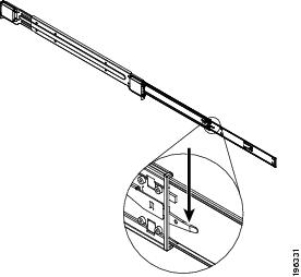
You must release the inner rails before you can attach them to the Multiservices Platform Series device. To do so, see Figure 2-3 and perform the procedure that follows.
Figure 2-3 Extending and Releasing the Inner Rail (Left Rail Assembly Shown)
Procedure
Step 1 ![]() Pull the inner rail out until it is fully extended.
Pull the inner rail out until it is fully extended.
Step 2 ![]() Press the inner rail locking tab down.
Press the inner rail locking tab down.
Step 3 ![]() Remove the inner rail from the rail assembly.
Remove the inner rail from the rail assembly.
Step 4 ![]() Repeat these steps for the other inner rail.
Repeat these steps for the other inner rail.
Attaching the Inner Rails to the Multiservices Platform Series Device
There are two inner rails. One attaches to each side of the Multiservices Platform Series device.
To attach the inner rails to the Multiservices Platform Series device, see Figure 2-4 and perform the procedure that follows.
Figure 2-4 Installing the Inner Rails
Procedure
Step 1 ![]() Place an inner rail firmly against a side of the Multiservices Platform Series device, aligning the hooks on the side of the device with the holes in the inner rail.
Place an inner rail firmly against a side of the Multiservices Platform Series device, aligning the hooks on the side of the device with the holes in the inner rail.
Make sure to use the correct (left or right) inner rail.
Step 2 ![]() Slide the inner rail toward the front of the Multiservices Platform Series device until the inner rail clicks into the locked position.
Slide the inner rail toward the front of the Multiservices Platform Series device until the inner rail clicks into the locked position.
Step 3 ![]() Secure the inner rail to the Multiservices Platform Series device by using one of the M4 x 6L screws, provided.
Secure the inner rail to the Multiservices Platform Series device by using one of the M4 x 6L screws, provided.
Step 4 ![]() Repeat Step 1 through Step 3 for the other inner rail.
Repeat Step 1 through Step 3 for the other inner rail.
Attaching the Outer Rails to a Rack
There are two outer rack rails. One attaches to each side of the rack and connects to the inner rack rails to hold the Multiservices Platform Series device in place. Each outer rack rail adjusts to fit racks between 26.5 and 36.4 inches (67.31 and 92.5 cm) deep.
To attach the outer rails to a rack, see Figure 2-5 and perform the procedure that follows.
Figure 2-5 Attaching Outer Rails to a Rack (Left Outer Rail Shown)
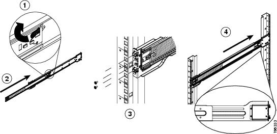
Procedure
Step 1 ![]() Press up the locking tab at the rear of the middle rail.
Press up the locking tab at the rear of the middle rail.
Step 2 ![]() Push the middle rail into the outer rail.
Push the middle rail into the outer rail.
Step 3 ![]() Hang the hooks on the front of the outer rail onto the slots on the front of the rack.
Hang the hooks on the front of the outer rail onto the slots on the front of the rack.
If you are using the square hole to round hole adapter set, hang the outer rail hooks onto the brackets that you installed. (See the "Installing Square Hole to Round Hole Adapters (Optional)" section for related information.)
Step 4 ![]() Secure the front of the outer rail to front of the rack by using one of the M5 x12L screws and washers, provided.
Secure the front of the outer rail to front of the rack by using one of the M5 x12L screws and washers, provided.
Step 5 ![]() Pull out the rear of the outer rail until and hang the hooks on the rear of the outer rail onto the slots on the rear of the rack.
Pull out the rear of the outer rail until and hang the hooks on the rear of the outer rail onto the slots on the rear of the rack.
If you are using the square hole to round hole adapter set, hang the outer rail hooks onto the brackets that you installed.
Step 6 ![]() Secure secure the front of the outer rail to front of the rack by using one of the M5 x12L screws and washers, provided.
Secure secure the front of the outer rail to front of the rack by using one of the M5 x12L screws and washers, provided.
Step 7 ![]() Repeat Step 1 through Step 5 for the other outer rail.
Repeat Step 1 through Step 5 for the other outer rail.
Placing the Multiservices Platform Series Device in the Rack
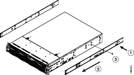
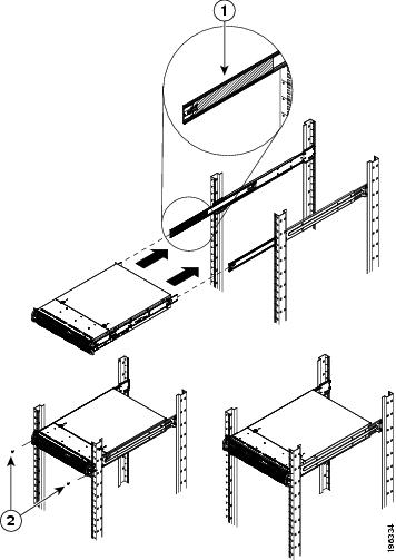
To place the Multiservices Platform Series device in a rack, see Figure 2-6 and perform the procedure that follows.
Figure 2-6 Placing the Server in a Rack
|
|
Ball-bearing shuttle |
|
Screws |
Procedure
Step 1 ![]() Confirm that the inner and outer rack rails are properly installed on the Multiservices Platform Series device and on the rack.
Confirm that the inner and outer rack rails are properly installed on the Multiservices Platform Series device and on the rack.
Step 2 ![]() Pull the middle rail out from the front of the outer rail until the ball-bearing shuttle is at the front locking position of the middle rail.
Pull the middle rail out from the front of the outer rail until the ball-bearing shuttle is at the front locking position of the middle rail.
Step 3 ![]() Align the inner rails that are attached to the Multiservices Platform Series device with the front of the middle rails that are attached to the rack.
Align the inner rails that are attached to the Multiservices Platform Series device with the front of the middle rails that are attached to the rack.
Step 4 ![]() Slide the inner rails into the middle rails, keeping even pressure on each side, until the locking tab of the inner rail clicks into the front of the middle rail.
Slide the inner rails into the middle rails, keeping even pressure on each side, until the locking tab of the inner rail clicks into the front of the middle rail.
The server is now locked into the fully extended position.
Step 5 ![]() Simultaneously press each locking tab (see Figure 2-3) and push the server all the way to the rear of the rack
Simultaneously press each locking tab (see Figure 2-3) and push the server all the way to the rear of the rack
Step 6 ![]() (Optional) Use M5 x 20L-T screws to secure the server handles to the front of the rack.
(Optional) Use M5 x 20L-T screws to secure the server handles to the front of the rack.
To remove the Multiservices Platform Series device from the rack, pull it out from the rack until the inner rail is fully extended, press each inner rail locking tab down (see Figure 2-3), then remove the server from the rack.
To remove an outer rail from the rack, remove the screws that attach it to the rack (if you used these screws), depress the black outer rail locking tabs that protrude through the front and rear rack mounting holes, lift the rail so its hooks are free from the mounting holes, and slide the rail pieces together so that you can remove from the rack.
Installing Hard Drives
If you ordered a Multiservices Platform Series 2-RU model, you must install the hard drives that you ordered for the system.
If you are installing six drives in a Multiservices Platform Series 2-RU chassis, install the drives in the left six slots as you face the front of the chassis. You can install drives in any order and into any available slot.
To install hard drives, follow these steps:
Procedure
Step 1 ![]() Press the red handle-release button on the front of the hard drive.
Press the red handle-release button on the front of the hard drive.
The drive handle extends from the front of the hard drive.
Step 2 ![]() With the red handle-release button of the hard drive facing toward you and to the right, push the drive straight into an open slot on the front of the Multiservices Platform Series chassis until you feel resistance.
With the red handle-release button of the hard drive facing toward you and to the right, push the drive straight into an open slot on the front of the Multiservices Platform Series chassis until you feel resistance.
Step 3 ![]() Push the drive handle toward the hard drive until the handle locks into place.
Push the drive handle toward the hard drive until the handle locks into place.
Step 4 ![]() Repeat these steps until each hard drive is installed.
Repeat these steps until each hard drive is installed.

Tip ![]() You may find it easiest to install the drives from the top down and from the right to the left. This approach allows the drives to slide into the slots more easily.
You may find it easiest to install the drives from the top down and from the right to the left. This approach allows the drives to slide into the slots more easily.
Connecting to Power, the Network, and External Devices
After you mount the Multiservices Platform Series device in a rack and install the hard drives, you are ready to connect a monitor, keyboard, and mouse to the server, and to connect the server to power and to your network. To make these connections, follow these steps:
Procedure
Step 1 ![]() Connect a monitor, keyboard, and mouse to the appropriate ports on the back of the Multiservices Platform Series device.
Connect a monitor, keyboard, and mouse to the appropriate ports on the back of the Multiservices Platform Series device.
Step 2 ![]() Connect a Category 5 or higher network cable to either network port on the back of the Multiservices Platform Series device and to your network switch.
Connect a Category 5 or higher network cable to either network port on the back of the Multiservices Platform Series device and to your network switch.
Step 3 ![]() Take either of these actions to connect power to the Multiservices Platform Series device:
Take either of these actions to connect power to the Multiservices Platform Series device:
•![]() If your Multiservices Platform Series device is configured with one power supply, connect the provided power cable to the power port on the back of the device, then plug the cable into an electrical outlet.
If your Multiservices Platform Series device is configured with one power supply, connect the provided power cable to the power port on the back of the device, then plug the cable into an electrical outlet.
•![]() If your Multiservices Platform Series device is configured with two power supplies, connect the two provided power cables to the two power ports on the back of the device, then plug each cable into an electrical outlet.
If your Multiservices Platform Series device is configured with two power supplies, connect the two provided power cables to the two power ports on the back of the device, then plug each cable into an electrical outlet.
Multiservices Platform Series Maintenance Operations
The following sections describe various maintenance operations that you may need to perform. For information about replacing a hard drive, see "Recovering from a Hard Drive Failure."
•![]() Removing the Chassis CoverFigure 2-6
Removing the Chassis CoverFigure 2-6
Removing the Chassis Cover
You must remove the chassis cover before installing internal fans and before performing various maintenance operations.
To remove the chassis cover, press and hold each release tab on the top of the chassis cover, slide the chassis cover toward the rear of the device, and lift it off. See Figure 2-7.
Note ![]() This figure illustrates a sample model. The procedure is similar on all models.
This figure illustrates a sample model. The procedure is similar on all models.
Figure 2-7 Removing the Chassis Cover
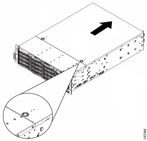
To replace the chassis cover, slide the chassis cover toward the front of the device until the release tabs engage. If you removed the screws that secure the chassis cover, replace these screws.
Replacing a System Fan
TheMultiservices Platform Series 2-RU model includes front fans and rear fans. The 1-RU model includes front fans only. Fans are hot swappable, which allows you to replace one fan at a time while the Multiservices Platform Series device is powered on.
The Cisco part number for fans is CIVS-FAN-2RU=.
To install fans, see Figure 2-8 and perform the procedure that follows.
Note ![]() This figure illustrates a sample model. The procedure is similar on all models.
This figure illustrates a sample model. The procedure is similar on all models.
Figure 2-8 Installing a Rear Fan
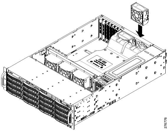
Procedure
Step 1 ![]() Remove the chassis cover as described in the "Removing the Chassis Cover" section.
Remove the chassis cover as described in the "Removing the Chassis Cover" section.
Step 2 ![]() To remove a fan, press and hold the release tab at the top of the fan and pull the fan straight up.
To remove a fan, press and hold the release tab at the top of the fan and pull the fan straight up.
Step 3 ![]() To install a fan, slide the fan into a fan slot until it locks into place.
To install a fan, slide the fan into a fan slot until it locks into place.
The fan fits in only one way.
Step 4 ![]() Replace the chassis cover.
Replace the chassis cover.
Replacing a Power Supply
The Multiservices Platform Series 2-RU model supports a second power supply for redundancy, which allow the devices to continue to operate if one power supplies fails. If a power supply does fail, you should replace it as soon as possible. Power supplies are hot swappable, which allows you to replace one power supply at a time while the Multiservices Platform Series device is powered on.
Note ![]() When you replace a power supply, make sure to replace it with the same model. The Cisco part number for the power supply is CIVS-PS-900=.
When you replace a power supply, make sure to replace it with the same model. The Cisco part number for the power supply is CIVS-PS-900=.
To replace a power supply, follow these steps:
Procedure
Step 1 ![]() Remove the AC power cord from the power supply that you are replacing.
Remove the AC power cord from the power supply that you are replacing.
Step 2 ![]() Push the release tab on the back of the power supply.
Push the release tab on the back of the power supply.
Step 3 ![]() Pull the power supply out using the handle that is provided.
Pull the power supply out using the handle that is provided.
Step 4 ![]() Push the new power supply into the power bay until you hear a click.
Push the new power supply into the power bay until you hear a click.
Step 5 ![]() Plug the AC power cord back into the supply.
Plug the AC power cord back into the supply.
Checking Air Flow
It is important to maintain proper air flow in and around the Multiservices Platform Series device so that the device operates properly and does not overheat. To ensure proper air flow, follow these guidelines:
•![]() Make sure that no objects obstruct the air flow into and out of the device. If necessary, route cables through the cable rack.
Make sure that no objects obstruct the air flow into and out of the device. If necessary, route cables through the cable rack.
•![]() Do not operate the device without hard drives.
Do not operate the device without hard drives.
•![]() Make sure that no wires or foreign objects obstruct air flow through the chassis. Pull excess cabling out of the air flow path or use shorter cables.
Make sure that no wires or foreign objects obstruct air flow through the chassis. Pull excess cabling out of the air flow path or use shorter cables.
•![]() Do not operate the device for extended periods without the chassis cover in place.
Do not operate the device for extended periods without the chassis cover in place.
•![]() Use only recommended server parts.
Use only recommended server parts.
 Feedback