Cisco Video Surveillance 8070 IP Camera Reference Guide, Release 1.0.5
Bias-Free Language
The documentation set for this product strives to use bias-free language. For the purposes of this documentation set, bias-free is defined as language that does not imply discrimination based on age, disability, gender, racial identity, ethnic identity, sexual orientation, socioeconomic status, and intersectionality. Exceptions may be present in the documentation due to language that is hardcoded in the user interfaces of the product software, language used based on RFP documentation, or language that is used by a referenced third-party product. Learn more about how Cisco is using Inclusive Language.
- Updated:
- April 18, 2018
Chapter: IP Camera Main Page
- Display Modes
- 1O (Original) Display Mode
- 1P (Single Panoramic) Display Mode
- 1R (Single Regional) Display Mode
- 2P (Dual Panoramic View) Display Mode
- 1O3R (One Original & Three Regional) Display Mode
- 4R (Four Regional) Display Mode
- 4R PRO (Four Regional Proactive) Display Mode
- 1O8R (One Original and Eight Regional) Display Mode
- PTZ Control Panel
- Live Video Window for MJPEG Video Streams
- Live Video Window for H.264 or H.265 Video Streams
IP Camera Main Page
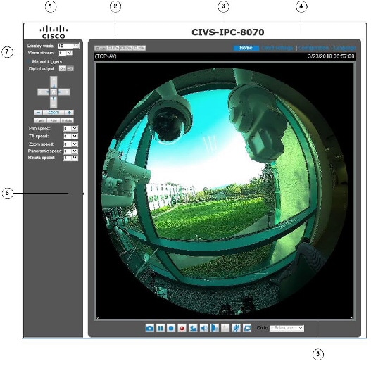
This chapter explains the layout of the IP camera Main page. It is composed of the following sections: Cisco Logo, Host Name, Camera Control Area, Configuration Area, Menu, and Live Video Window.
Figure 3-1 illustrates the Main page.
|
|
|
|
|
|
|
|
Host Name. The host name can be customized to fit your needs. For more information, see the “System > General settings” section. |
|
|
|
|
|
Video view window. Shows the video stream from the IP camera. The information in this window depends on the video stream configuration. Depending on the camera model and camera configuration, some buttons may not be available. See the “Live Video Window for MJPEG Video Streams” section and the “Live Video Window for H.264 or H.265 Video Streams” section. |
|
|
Hide button. You can click the hide button to hide or display the control panel. |
|
|
– – – – – Most display modes are available in the Ceiling mount type.
|
Display Modes
This section describes the display modes that you can choose from the Camera Control area.
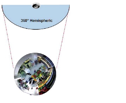
1O (Original) Display Mode
When mounted on a ceiling, the fisheye camera can cover an approximate of 64 m² surveillance area (installed at a height of approximately 3 meters), while still keeping details in videos with recognizable facial features of people trafficking through the area.
The 1O view is especially adequate for taking an overview glimpse of the surveillance area when mounted on the ceiling.
Figure 3-2 shows the 1O view (original view).
Figure 3-2 1O View (Original View
1P (Single Panoramic) Display Mode
With image correction algorithms in firmware, the hemispheric image is transformed into a rectilinear stripe in the 1P display mode. You can use the PTZ panel or simply use mouse swipe to quickly move through the 360º panoramic view. (Mouse control on the Panoramic view is available with the Ceiling mount type.)
When mounted on a wall, this mode can cover a 180º overview from side to side, for example., on the entrance of a building or a corridor.

Note![]() The 1P view is apt for an overview, the Zoom in/out function does not apply in this mode.
The 1P view is apt for an overview, the Zoom in/out function does not apply in this mode.
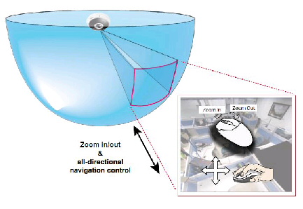
1R (Single Regional) Display Mode
The 1R mode provides access to one image section within the hemisphere. You can zoom in or out (using the mouse wheel or PTZ panel) or travel to other areas in the hemisphere using mouse clicks and swipes. A single click on a particular object can bring the object to the center of your view window. Click and hold down the left mouse button, and you can swipe the view in all directions.
Figure 3-3 shows the 1R view.
Figure 3-3 1R View (Single Regional View)
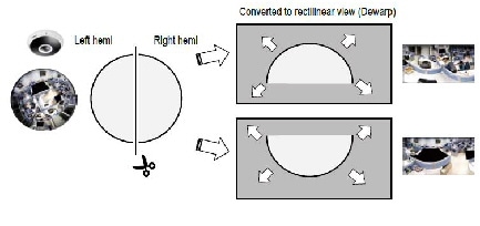
2P (Dual Panoramic View) Display Mode
Similar to 1P, the 2P display mode provides simultaneous access to both the left and right sections of a hemisphere. Both panoramic views are corrected into a more viewable dewarped image. You can use a mouse click and swipe to quickly scroll horizontally through the surveillance area.
Note![]() The dividing line falls approximately on the center of the Cisco logo on the camera.
The dividing line falls approximately on the center of the Cisco logo on the camera.
Figure 3-4 shows the 2P View (Panoramic View).
Figure 3-4 2P View (Panoramic View)
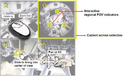
1O3R (One Original & Three Regional) Display Mode
The 1O3R mode provides access to multiple live view sections within the hemisphere and the reference to their relative positions on an Original circular view. The FOV indicators (#1 ~ #3) interact with your current operation as you may zoom in/out or move the live view window to a different place.
You can zoom in or out or travel to other areas within the hemisphere using identical methods as previously described in the 1R mode.
You can also change the locations of Regional views by dragging the FOV indicators on the “Original”
Figure 3-5 shows the 1O3R (original and regional) mode screen control.
Figure 3-5 1O3R (Original and Regional) Mode Screen Control

Tip![]() In a Regional view displaying 100% of video feed (via the Resize buttons—see on page 3-2), your mouse wheel can be used to scroll the view window vertically before you click on a live image. After you click on the live image, the mouse wheel becomes the zoom in/out tool.
In a Regional view displaying 100% of video feed (via the Resize buttons—see on page 3-2), your mouse wheel can be used to scroll the view window vertically before you click on a live image. After you click on the live image, the mouse wheel becomes the zoom in/out tool.
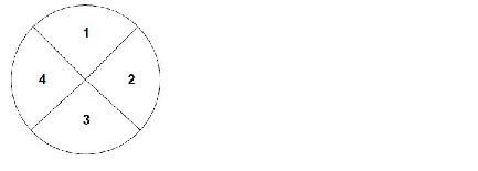
4R (Four Regional) Display Mode
The view control and look and feel are identical to that as described in the 1O3R mode except that the original circular view is absent from this mode.
Figure 3-5 illustrates the 4R (four regional) display mode.
Figure 3-6 4R (Four Regional) Display Mode
4R PRO (Four Regional Proactive) Display Mode
The 4R PRO mode is similar to the 4R mode except that the quad view windows consecutively rotate in correspondence to the change of view area in one window. Zoom in/out and tilt control is not available in this mode.
1O8R (One Original and Eight Regional) Display Mode
The view control and look and feel are identical to that as described in the 1O3R mode.
Note![]() If you change the position of a view in hemisphere, for example, the #3 window, you may lose the configuration change by switching to another display mode. The live view window does not automatically save your view section layout.
If you change the position of a view in hemisphere, for example, the #3 window, you may lose the configuration change by switching to another display mode. The live view window does not automatically save your view section layout.
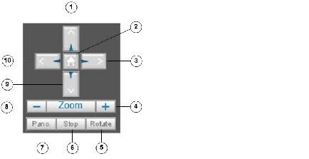
PTZ Control Panel
Figure 3-7 shows the PTZ Control Panel.
|
|
|
|
|
|
|
|
|
|
|
|
|
|
After you configure the list of preset positions (including the zoom-in action on a particular position), click this button to command the camera to display the preset positions in a consecutive order. The camera will display those positions continuously. For more information, see the “PTZ > PTZ settings” section. |
|
|
|
|
|
Start the automatic horizontal pan (360° continuous rotation). |
|
|
|
|
|
|
|
|
Adjust the speed of these controls when exerted:
|
|
|
|
|
|
|---|---|---|---|---|
Live Video Window for MJPEG Video Streams
When the video mode is set to MJPEG, the Live Video window appears as shown in Figure 3-8. (Depending on the camera model and camera configuration, some buttons may not be available.)
Figure 3-8 Live Video Window for MJPEG
|
|
Time. Display the current date and time. For more information, see the “Media > Image” section. |
|
|
Video title. The video title can be configured. For more information, see the “Media > Image” section. |
|
|
Title and Time. Video title and time can be stamped on the streaming video. For more information, see the “Media > Image” section. |
|
|
Snapshot button. Click this button to capture and save still images. The captured images will be displayed in a pop-up window. Right-click the image and choose Save Picture As to save it in JPEG (*.jpg) or BMP (*.bmp) format. |
|
|
Start MP4 Recording button. Click this button to record video clips in MP4 file format to your computer. Press the Stop MP4 Recording button |
|
|
Full Screen button. Click this button to switch to full screen mode. Press the Esc key to switch back to normal mode. |
 to end recording. When you exit the web browser, video recording stops accordingly. To specify the storage destination and file name, see the
 For PTZ settings, see the “PTZ > PTZ settings” section.
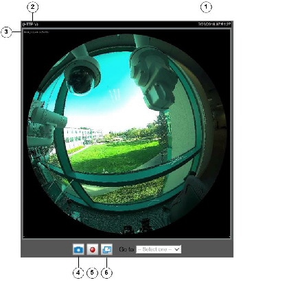
Live Video Window for H.264 or H.265 Video Streams
When the video mode is set to H.264 or H.265, the Live Video window appears as shown in Figure 3-9. For further configuration, see Chapter4, “Client Settings”
Figure 3-9 Live Video Window for H.264 or H.265
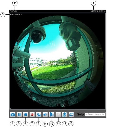
The Live Video window appears as shown in Figure 3-9.
|
|
Time. Display the current date and time. For more information, see the “Media > Image” section. |
|
|
Video title. The video title can be configured. For more information, see the “Media > Image” section. |
|
|
Title and Time. Video title and time can be stamped on the streaming video. For more information, see the “Image settings” section. |
|
|
Snapshot button. Click this button to capture and save still images. The captured images will be displayed in a pop-up window. Right-click the image and choose Save Picture As to save it in JPEG (*.jpg) or BMP (*.bmp) format. |
|
|
Pause button. Pause the transmission of the streaming media. The button becomes the Resume button |
|
|
Stop button. Stop the transmission of the streaming media. Click the Resume button |
|
|
Start MP4 Recording button. Click this button to record video clips in MP4 file format to your computer. Press the Stop MP4 Recording button |
|
|
Volume button. When the Mute function is not activated, move the slider bar to adjust the volume on the local computer. |
|
|
Mute button. Turn off the volume on the local computer. The button becomes the Audio On button |
|
|
Talk button. Click this button to talk to people around the camera. Audio will project from the external speaker connected to the camera. Click this button again to end talking transmission. |
|
|
Mic Volume button. When the Mute function is not activated, move the slider bar to adjust the microphone volume on the local computer. |
|
|
Mute. Turn off the Mic volume on the local computer. The button becomes the Mic On button after clicking the Mute button. |
|
|
Full Screen. Click this button to switch to full screen mode. Press the Esc key to switch back to normal mode. |
 after clicking the Pause button.
 to continue transmission.
 to end recording. When you exit the web browser, video recording stops accordingly. To specify the storage destination and file name, see the
  after clicking the Mute button.
 Feedback