Cisco Video Surveillance 8070 IP Camera Reference Guide, Release 1.0.5
Bias-Free Language
The documentation set for this product strives to use bias-free language. For the purposes of this documentation set, bias-free is defined as language that does not imply discrimination based on age, disability, gender, racial identity, ethnic identity, sexual orientation, socioeconomic status, and intersectionality. Exceptions may be present in the documentation due to language that is hardcoded in the user interfaces of the product software, language used based on RFP documentation, or language that is used by a referenced third-party product. Learn more about how Cisco is using Inclusive Language.
- Updated:
- April 18, 2018
Chapter: Getting Started
Getting Started
This chapter provides information about getting started with and understanding the IP camera. It includes the following sections:
Overview
The Cisco Video Surveillance 8070 IP Camera is a high-definition HD), fully functioning video endpoint that is equipped with a 12-megapixel sensor and a fisheye lens that can deliver impressive 180° panoramic views and 360° surround views. This IP camera provides industry-leading image quality and processing power, and can be deployed in both indoor and outdoor environments.
Key features and benefits of the Cisco Video Surveillance cameras include:
- Outstanding multi-view layouts—360° surround views and multiregion client dewarped views, with Digital PTZ functionality.
- True high-definition video—This 12-megapixel camera streams crisp and clear video at resolutions up to 2816 x 2816, while maintaining low network bandwidth.
- Dual streaming—The camera can stream H.264, H.265, and MJPEG video simultaneously. Each video stream can be configured with independent resolution, quality, and frame-rate settings.
- Day/night operation—The camera provides true day-night functionality and includes an infrared-cut filter that automatically switches to night mode in low-light scenes. This function can be set to manual, automatic, or scheduled control.
- Flexible power options—The camera supports Power over Ethernet plus (PoE+) (802.3at compliant) or 12V DC.
- Mounting options—The cameras can be installed to a ceiling or wall.
Physical Description
The following figures illustrate the cameras:
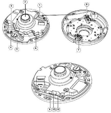
- Figure 1-1—Cisco Video Surveillance 8070 IP Camera inner view
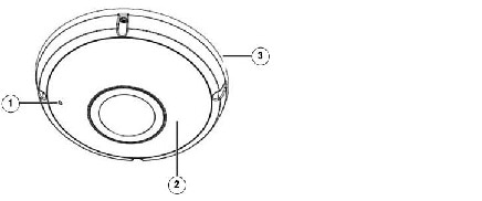
- Figure 1-2—Cisco Video Surveillance 8070 IP Camera outer view
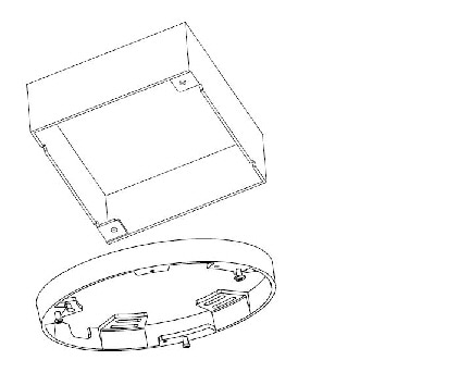
Figure 1-1 Cisco Video Surveillance 8070 IP Camera Inner View
|
|
|
|
|
|
|
|
|
|
|
|
|
|
|
|
|
|
|
|
|
|
|
|
|
|
|
|
|
|
|
|
Figure 1-2 Cisco Video Surveillance 8070 IP Camera Outer View
|
|
|
|
|
|
|
|
LED Definitions
Table 1-1 describes the LEDs on the Cisco Video Surveillance IP Camera.
Mounting Positions
Figure 1-3 shows the mounting hole positions and the dimensions of the base plate.
Figure 1-3 Camera Base Plate Mounting Positions
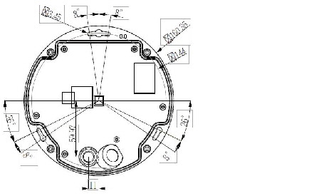
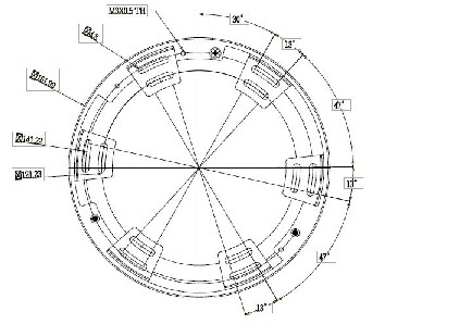
Figure 1-4 Camera Mounting Plate Mounting Positions
Power Adapters
This product is intended to be supplied by a Listed Power Adapter with LPS, rated 0.68-0.44A for PoE 37-57V; 1.67A for DC12V |
Hardware Installation
To install the Cisco Video Surveillance 8070 IP Camera, on a ceiling or wall, follow these steps:
Step 1![]() Make a note of the MAC address of the camera.
Make a note of the MAC address of the camera.
The MAC address is printed on the label that is attached to the camera.
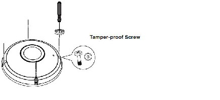
Step 2![]() Use the supplied screwdriver to loosen the four screws and detach the dome cover from the camera base.
Use the supplied screwdriver to loosen the four screws and detach the dome cover from the camera base.
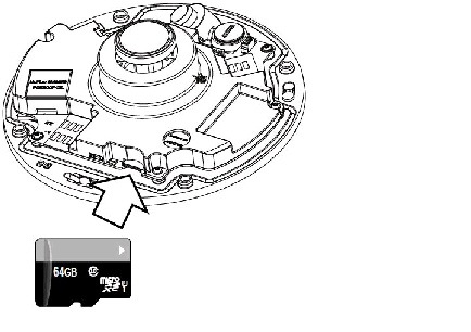
Step 3![]() If edge recording is preferred, install a microSD card in the camera.
If edge recording is preferred, install a microSD card in the camera.
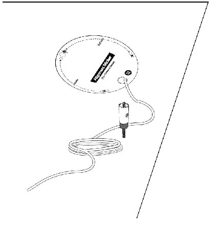
Step 4![]() Prepare the wiring, and drill a cabling hole with the aid of the included alignment sticker.
Prepare the wiring, and drill a cabling hole with the aid of the included alignment sticker.
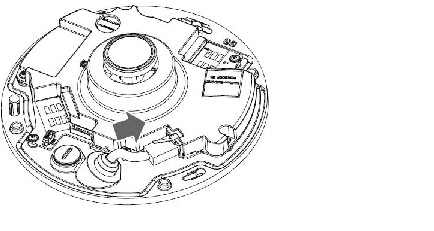
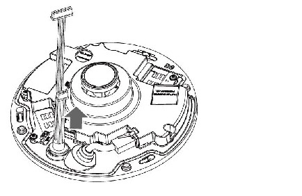
Step 5![]() Remove the stoppers and route cables through the openings.
Remove the stoppers and route cables through the openings.
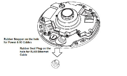
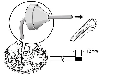
Step 6![]() Drill a hole on the rubber seal plug and insert an Ethernet cable through the opening. Strip part of the sheath from the Ethernet cable.
Drill a hole on the rubber seal plug and insert an Ethernet cable through the opening. Strip part of the sheath from the Ethernet cable.
Recommended cable gauge: 5 to 8mm.
Step 7![]() Drill a hole on the rubber seal plug and insert an Ethernet cable through the opening. Strip part of the sheath from the Ethernet cable.
Drill a hole on the rubber seal plug and insert an Ethernet cable through the opening. Strip part of the sheath from the Ethernet cable.
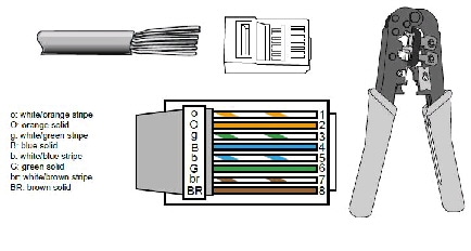
Step 8![]() You will need an RJ45 crimping tool to attach the Ethernet wires to a connector. When done, connect the cable to the camera’s Ethernet RJ45 socket.
You will need an RJ45 crimping tool to attach the Ethernet wires to a connector. When done, connect the cable to the camera’s Ethernet RJ45 socket.
Step 9![]() Feed the Ethernet cable from the bottom of the camera and through the hole. Attach the rubber seal plug for water proofing.
Feed the Ethernet cable from the bottom of the camera and through the hole. Attach the rubber seal plug for water proofing.
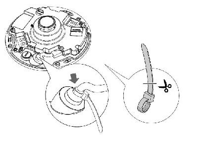
Step 10![]() Use the included cable tie to fasten the top of the rubber seal so that the position of the Ethernet cable will not alter. When done, cut the excessive part of the cable tie.
Use the included cable tie to fasten the top of the rubber seal so that the position of the Ethernet cable will not alter. When done, cut the excessive part of the cable tie.
Step 11![]() If the DI/DO combo cable is preferred, install the supplied rubber washer to the cable as shown in the picture. Feed the cable from the bottom of the camera and tighten the plastic nut for waterproofing.
If the DI/DO combo cable is preferred, install the supplied rubber washer to the cable as shown in the picture. Feed the cable from the bottom of the camera and tighten the plastic nut for waterproofing.
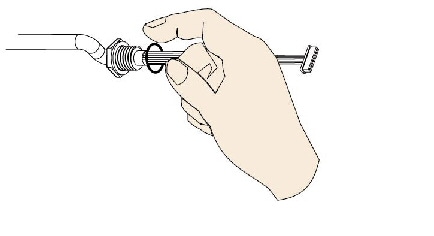
If you are not powering the camera over a PoE switch, use the DC 12V connector on the DI/DO combo cable.
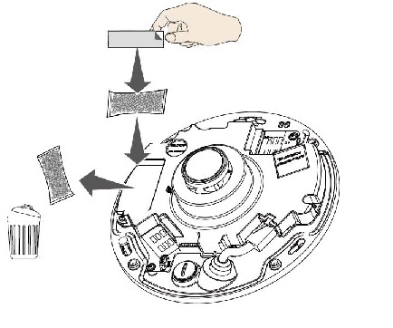
Replace the desiccant bag on the camera. This is very important to reduce the moisture level inside the camera. Replace it whenever you open the camera dome cover.
Step 12![]() To perform a direct installation, take the following actions.
To perform a direct installation, take the following actions.
To perform an installation using the mount bracket, skip to Step 13.
Direct installation instructions:
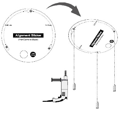
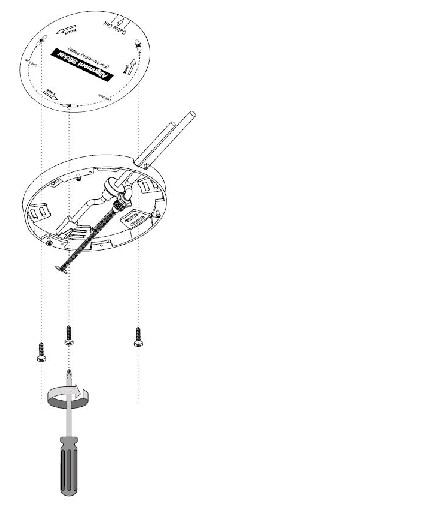
a.![]() Attach the supplied alignment sticker for camera base to the ceiling/wall. Using the three circles on the sticker, drill three pilot holes into the ceiling. Then hammer the three supplied plastic anchors into the holes.
Attach the supplied alignment sticker for camera base to the ceiling/wall. Using the three circles on the sticker, drill three pilot holes into the ceiling. Then hammer the three supplied plastic anchors into the holes.
If preferred, drill a cabling hole on the ceiling or wall, and feed the cables through the hole.
b.![]() Secure the camera base to the ceiling/wall with three supplied screws.
Secure the camera base to the ceiling/wall with three supplied screws.
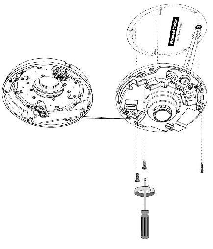
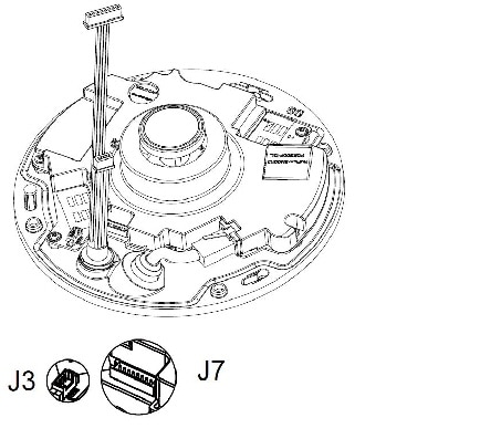
c.![]() Connect the white headers of the DI/DO combo cable to the J3 and J7 headers on the camera.
Connect the white headers of the DI/DO combo cable to the J3 and J7 headers on the camera.
d.![]() Attach the dome cover. Secure the four screws using the supplied T10 stardriver. Make sure all camera parts are securely installed.
Attach the dome cover. Secure the four screws using the supplied T10 stardriver. Make sure all camera parts are securely installed.
Arrange the cables neatly to avoid getting in the way when the dome cover is attached.
After you attach the dome cover, continue with Step 14.
Step 13![]() To perform an installation using the mount bracket:
To perform an installation using the mount bracket:
a.![]() Attach the supplied alignment sticker for the supplied mounting plate to the ceiling or wall. (There are two different alignment stickers.)
Attach the supplied alignment sticker for the supplied mounting plate to the ceiling or wall. (There are two different alignment stickers.)
Using the three circles on the sticker, drill three holes into the ceiling. Then hammer the three supplied plastic anchors into the holes.
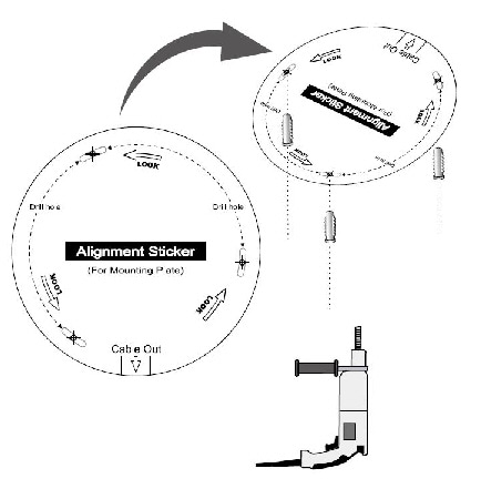
b.![]() Arrange and feed the cables through the side of the mount bracket. Secure the mount bracket to the ceiling or wall using the supplied screws.
Arrange and feed the cables through the side of the mount bracket. Secure the mount bracket to the ceiling or wall using the supplied screws.
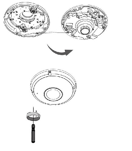
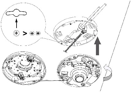
c.![]() Install the camera to the mount bracket. Align the double-sided keyhole slot with the largest rivet head on the mount bracket. Turn the camera counter-clockwise as shown in the following figure:
Install the camera to the mount bracket. Align the double-sided keyhole slot with the largest rivet head on the mount bracket. Turn the camera counter-clockwise as shown in the following figure:
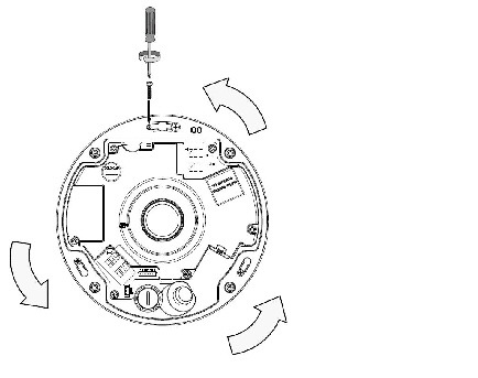
d.![]() A small mount hole will be revealed through the keyhole slot. Secure the camera by tightening a flat-head screw.
A small mount hole will be revealed through the keyhole slot. Secure the camera by tightening a flat-head screw.
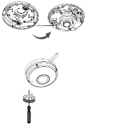
e.![]() Install the dome cover using the T10 star driver.
Install the dome cover using the T10 star driver.
f.![]() You may also use the diagonal holes on the mounting plate to install the camera to a U.S. standard 4 in. junction box.
You may also use the diagonal holes on the mounting plate to install the camera to a U.S. standard 4 in. junction box.
Step 14![]() If you are using the DI/DO combo cable, take these actions:
If you are using the DI/DO combo cable, take these actions:
a.![]() Connect RJ45 Ethernet cable to a switch.
Connect RJ45 Ethernet cable to a switch.
b.![]() Connect the power cable from the Network Camera to a power outlet.
Connect the power cable from the Network Camera to a power outlet.
c.![]() If you have external devices such as sensors and alarms, make the connection from the general I/O terminal block.
If you have external devices such as sensors and alarms, make the connection from the general I/O terminal block.
Important: If DC power is preferred, it should comply with O/P: 12VDC, 2A min., L.P.S. per IEC 60950-1.
Hardware Reset
The recessed button (see Figure 1-1) is used to reset the system or restore the factory default settings. Sometimes resetting the system can return the camera to normal operation. If the system problems remain after reset, restore the factory settings and install again.
MicroSD/SDHC/SDXC Card Capacity
The camera is compliant with SD/SDHC/SDXC 32GB, 64GB, and other preceding standard SD cards.
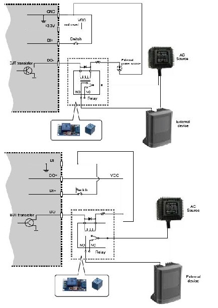
DI/DO Diagram
- The DO+ pin (5V) provides 5V±10% output voltages, and the max. load is 50mA.
- The max. voltage for DO- pins is 30VDC (external power).
In order to control AC devices, Figure 1-6 can be taken into consideration. This figure uses a relay to control the ON/OFF condition of the AC device.
- An external relay can be triggered by using the DO+ or by an external power source, depending on the type of relay you use.
- In case of using an individual relay (instead of using a relay module), for protection against voltage or current spikes, a transient voltage suppression diode must be connected in parallel with the inductive load.
Network Deployment
The following sections provide information about deploying the camera on a network:
- Setting up the Network Camera over the Internet
- Set up the Network Camera through Power over Ethernet (PoE)
Setting up the Network Camera over the Internet
There are several ways to set up the Network Camera over the Internet. The first way is to set up the Network Camera behind a router. The second way is to utilize a static IP. The third way is to use PPPoE.
Internet Connection via a Router
Before enabling the access to the Network Camera over the Internet, make sure you have a router and follow these steps:
Step 1![]() Connect your camera behind a router, the Internet environment is illustrated in Figure 1-7.
Connect your camera behind a router, the Internet environment is illustrated in Figure 1-7.
Figure 1-7 Connecting the Camera Via a Router
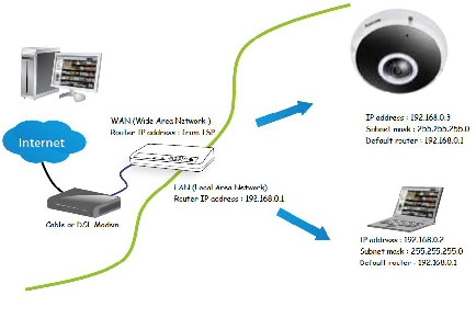
Step 2![]() In this case, if the Local Area Network (LAN) IP address of your camera is 192.168.0.3, forward the following ports for the camera on the router.:
In this case, if the Local Area Network (LAN) IP address of your camera is 192.168.0.3, forward the following ports for the camera on the router.:
If you have changed the port numbers on the Network page, open the ports accordingly on your router. For information about how to forward ports on the router, see your router documentation.
Step 3![]() Find out the public IP address of your router provided by your Internet Service Provider (ISP).
Find out the public IP address of your router provided by your Internet Service Provider (ISP).
Use the public IP and the secondary HTTP port to access the camera from the Internet. See the “Network > General settings” section for more information.
For example, your router and IP settings may look like this:
|
|
|
|
|---|---|---|
Configure the router, virtual server, or firewall so that the router can forward any data coming into a preconfigured port number to a camera on the private network, and allow data from the camera to be transmitted to the outside of the network over the same path.
|
|
|
|---|---|
When properly configured, you can access a camera behind the router using the HTTP request such as: http://122.146.57.120:8000.
If you change the port numbers on the Network configuration page, open the ports accordingly on your router. For example, you can open a management session with your router to configure access through the router to the camera within your local network. See your network administrator for router configuration if you have trouble with the configuration.
For more information about network configuration options (such as that of streaming ports), choose Configuration > Network in the IP camera web-based interface. Cisco also provides the automatic port forwarding feature as an NAT traversal function with the precondition that your router must support the UPnP port forwarding feature.
Internet connection with static IP
Choose this connection type if you are required to use a static IP for the Network Camera. See the “Network > General settings” section for more information.
Internet connection via PPPoE (Point-to-Point over Ethernet)
Choose this connection type if you are connected to the Internet via a DSL Line. See the description of PPPoE (Point-to-point over Ethernet) in the “Network Type” section.
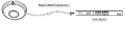
Set up the Network Camera through Power over Ethernet (PoE)
The camera is PoE-compliant, allowing transmission of power and data via a single Ethernet cable. Figure 1-8 illustrates how to connect the camera to a PoE-enabled switch via an Ethernet cable.
The camera is only to be connected to PoE networks without routing to outside plants.
For PoE connection, use only UL listed I.T.E. with PoE output.
Figure 1-8 Connecting the Camera to a PoE-Enabled Switch via an Ethernet Cable
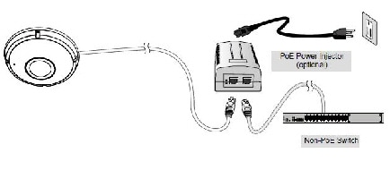
If your switch/router does not support PoE, use a PoE power injector (optional) to connect between the Network Camera and a non-PoE switch., as shown in Figure 1-9.
Figure 1-9 Connecting the Camera to a Non-PoE Switch

Tip![]() If you encounter problems with displaying live view or the onscreen plug-in control, you may try to remove the plug-ins that might have been installed on your computer. Remove the following folder: C:\Program Files (x86)\Camera Stream Controller\.
If you encounter problems with displaying live view or the onscreen plug-in control, you may try to remove the plug-ins that might have been installed on your computer. Remove the following folder: C:\Program Files (x86)\Camera Stream Controller\.
If you forget the root (administrator) password for the camera, you can restore the camera defaults by pressing the reset button for longer than 5 seconds.
If DHCP is enabled in your network, and the camera cannot be accessed, run the Shepherd utility to search the network. If the camera has been configured with fixed IP that does not comply with your local network, you may see its default IP 169.254.x.x. If you still cannot find the camera, you can restore the camera to its factory defaults.
If you change your network parameters, e.g., added a connection to a LAN card, restart the Shepherd utility.
 Feedback