- About This Guide
- About the Firepower 8000 Series
- Hardware Specifications
- Installing a Firepower 8000 Series Device
- Using the LCD Panel on a Firepower Device
- Deploying on a Management Network
- Deploying Firepower Managed Devices
- Power Requirements for Firepower 8000 Series Devices
- Inserting and Removing Firepower 8000 Series Modules
- Installing a Malware Storage Pack
Firepower 8000 Series Hardware Installation Guide
Bias-Free Language
The documentation set for this product strives to use bias-free language. For the purposes of this documentation set, bias-free is defined as language that does not imply discrimination based on age, disability, gender, racial identity, ethnic identity, sexual orientation, socioeconomic status, and intersectionality. Exceptions may be present in the documentation due to language that is hardcoded in the user interfaces of the product software, language used based on RFP documentation, or language that is used by a referenced third-party product. Learn more about how Cisco is using Inclusive Language.
- Updated:
- July 9, 2016
Chapter: Inserting and Removing Firepower 8000 Series Modules
Inserting and Removing Firepower 8000 Series Network Modules
The Firepower 8000 Series devices use network modules (NetMods) that contain either copper or fiber sensing interfaces, allowing for modular flexibility in your deployment. The devices can be shipped fully assembled or you can install the modules. You may also need to replace or change a module.
Use the procedures in this section to insert a new NetMod or to remove or replace a preinstalled NetMod.

Caution You cannot hot-swap NetMods. You must power down and unplug both power cords from the appliance before inserting or removing modules.

Note When replacing NetMods on a stacked configuration, complete all procedures on the secondary units first, then perform any replacements on the primary unit.
About Firepower 8000 Series Modules
For a new appliance, assemble your device before installing the Firepower System. See the assembly instructions included with your NetMods.
Note Replacing a NetMod can alter the configuration of a fully configured Korean-certified (KCC mark) Firepower device. For more information, see the original configuration documentation for your appliance and the Regulatory Compliance and Safety Information for FirePOWER and FireSIGHT Appliances document.
Identify the Module Parts
The sensing interfaces for the Firepower 8000 Series appliances can be delivered with copper or fiber interfaces, and can have configurable bypass sensing interfaces or non-bypass sensing interfaces. All NetMods contain the same parts, regardless of sensing interface, speed, or size of the module.
Figure B-1 Example NetMod or Slot Cover (open)
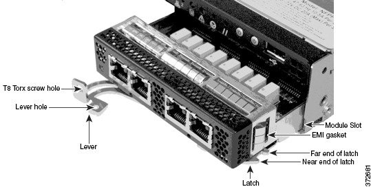
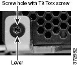
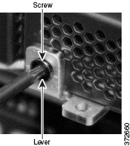
Figure B-2 Example NetMod Lever (closed with screw in hole)
See Firepower 8000 Series Modules for complete information about Firepower 8000 Series modules.
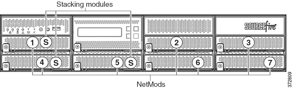
Module Slots on the Firepower 8000 Series Devices
The following illustrations of the front of the chassis indicates the location of the module slots that contain NetMods for sensing interfaces.
Figure B-3 Firepower 81xx Family Primary Device
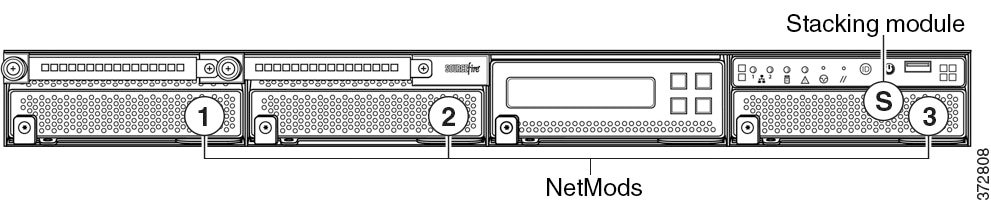
Figure B-4 Firepower 82xx Family and 83xx Family Primary Device
Stacking Configuration Considerations
A stacking module combines the resources of two or more identically configured appliances. See Firepower 8000 Series Stacking Module for information about which Firepower 8000 Series models support stacking. Configure the modules as follows for stacked devices:
- You can use a device stack as you would a single device in your deployment, with a few exceptions. If you have Firepower 8000 Series devices in a high-availability pair, you cannot stack a device high-availability pair or a device in a high-availability pair.
- When replacing NetMods on a stacked configuration, complete all procedures on the secondary units first, then perform any replacements on the primary unit.
- Install NetMods on the primary device only.
- Install one stacking module on the primary device for each stacked secondary device, and one stacking module on each secondary device.
See Using Devices in a Stacked Configuration for complete information about stacking. See the “8000 Series Device Stacking” chapter in the Firepower Management Center Configuration Guide for information about managing device stacks with your Firepower Management Center.
Included Items
Your module assembly kit includes a T8 Torx screwdriver and one or more of the following modules:
- quad-port 1000BASE-T copper configurable bypass NetMod. For more information, see Quad-Port 1000BASE-T Copper Configurable Bypass NetMod.
- quad-port 1000BASE-SX fiber configurable bypass NetMod. For more information, see Quad-Port 1000BASE-SX Fiber Configurable Bypass NetMod.
- dual-port 10GBASE (MMSR or SMLR) fiber configurable bypass NetMod. For more information, see Dual-Port 10GBASE (MMSR or SMLR) Fiber Configurable Bypass NetMod.
- dual-port 40GBASE-SR4 fiber configurable bypass NetMod. For more information, see Dual-Port 40GBASE-SR4 Fiber Configurable Bypass NetMod.
Note Use this dual-slot NetMod only on the 40G-capacity Firepower 8250 or Firepower or AMP 8350. If you need to upgrade your device, see the Cisco 8000 Series Device 40G Capacity Upgrade Guide.
- quad-port 1000BASE-T copper non-bypass NetMod. For more information, see Quad-Port 1000BASE-T Copper Non-Bypass NetMod.
- quad-port 1000BASE-SX fiber non-bypass NetMod.quad-port 1000BASE-SX fiber non-bypass NetMod. For more information, see Quad-Port 1000BASE-SX Fiber Non-Bypass NetMod.
- quad-port 10GBASE (MMSR or SMLR) fiber non-bypass NetMod. For more information, see Quad-Port 10GBASE (MMSR or SMLR) Fiber Non-Bypass NetMod.
Caution The quad-port 10GBASE fiber non-bypass NetMod contains non-removable small form factor pluggable (SFP) transceivers. Any attempt to remove the SFPs can damage the module.
- stacking module. For more information, see Stacking Module.
Note If you install a NetMod in an incompatible slot on your Firepower device or a NetMod is otherwise incompatible with your system, an error or warning message appears in the web interface on the managing Management Center when you attempt to configure the NetMod. Contact support for assistance.
Power Down the Appliance
Caution You cannot hot-swap NetMods. You must power down and unplug both power cords from the appliance before inserting or removing modules.
Prepare to insert or remove your module using the following guidelines:

Tip You can insert the NetMod into any available, compatible slot.
- Confirm that the EMI gaskets are in place.
- If your appliance is part of a device stack or high-availability pair, place the device in maintenance mode from the Firepower Management Center:
– Choose Devices > Device Management .
– Next to the stack member or peer you want to place into maintenance mode, click the toggle maintenance mode icon ( ).
).
– Click Yes to confirm maintenance mode.
Step 1 To shut down the appliance, choose System > Configuration .
Step 3 Click Run Command next to Shutdown Appliance .
Step 4 Unplug all power cords from the appliance.
Remove the Module or Slot Cover
Use proper electrostatic discharge (ESD) practices such as wearing wrist straps and using an ESD work surface when handling the modules. Store unused modules in an ESD bag or box to prevent damage.
Step 1 Remove and reserve the T8 Torx screw from the lever of the module using the included screwdriver.
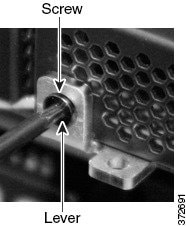
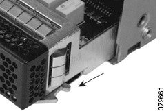
Step 2 Pull the lever away from the module to release the latch.
Step 3 Slide the module out of the slot.
Insert the Module or Slot Cover
Use proper electrostatic discharge (ESD) practices such as wearing wrist straps and using an ESD work surface when handling the modules. Store unused modules in an ESD bag or box to prevent damage.
Step 1 Remove and reserve the T8 Torx screw from the lever of the module using the included screwdriver.
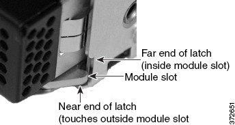
Step 2 Pull the lever away from the module to open the latch. The near end of the latch is visible. The far end of the latch is inside the module.
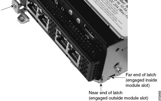
Step 3 Insert the module into the slot until the far end of the latch is inside the slot and the near end of the latch touches the outside of the module slot.
Step 4 Push the lever toward the module so that the latch engages and pulls the module into the slot.
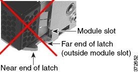
Caution Do not use excessive force. If the latch does not engage, remove and realign the module, then try again.
Step 5 Press firmly on the screw hole to push the lever fully against the module to secure the latch.
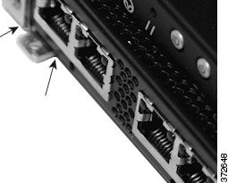
The lever is fully against the module, and the module is flush with the chassis.
Step 6 Insert and tighten the reserved T8 Torx screw into the lever.

Restart the Appliance
- Plug in all power cords to the appliance.
- Wait until the appliance is fully powered up. This could take several minutes.
Step 1 Choose System > Configuration .
Step 3 Click Run Command next to Restart Appliance Console .
Verify the NetMod from the Firepower Management Center
Step 1 Choose Devices > Device Management .
Step 2 Next to the device where you want to view the interfaces, click the edit icon ( ).
).
Step 3 Verify the interfaces on the Interfaces tab.
Step 4 If your appliance is part of a device stack or high-availability pair, bring the device out of maintenance mode from the Firepower Management Center:
- Choose Devices > Device Management .
- Next to the stack member or peer, click the toggle maintenance mode icon (
 ) to bring the device out of maintenance mode.
Apply Changes to the Appliance
After you make changes to the configuration of a device, a device cluster, or a device stack, you must apply the changes before they take effect throughout the system. Note that the device must have unapplied changes or this option remains disabled.
Note that if you edit interfaces and reapply a device policy, Snort restarts for all interface instances on the device, not just those that you edited.
Tip You can apply device changes from the Device Management page or from the Interfaces tab of the appliance editor.
Step 1 Select Devices > Device Management .
Step 2 Next to the device where you want to apply changes, click the apply icon ( ).
).
Step 3 When prompted, click Apply .
 Feedback