- About This Guide
- Index
- Glossary
-
- Configuring IPSec and ISAKMP
- Configuring L2TP over IPSec
- Setting General VPN Parameters
- Configuring Tunnel Groups, Group Policies, and Users
- Configuring IP Addresses for VPN
- Configuring Remote Access VPNs
- Configuring Network Admission Control
- Configuring Easy VPN on the ASA 5505
- Configuring the PPPoE Client
- Configuring LAN-to-LAN VPNs
- Configuring Clientless SSL VPN
- Configuring AnyConnect VPN Client Connections
- Configuring AnyConnect Host Scan
Cisco ASA 5500 Series Configuration Guide using the CLI, 8.4 and 8.6
Bias-Free Language
The documentation set for this product strives to use bias-free language. For the purposes of this documentation set, bias-free is defined as language that does not imply discrimination based on age, disability, gender, racial identity, ethnic identity, sexual orientation, socioeconomic status, and intersectionality. Exceptions may be present in the documentation due to language that is hardcoded in the user interfaces of the product software, language used based on RFP documentation, or language that is used by a referenced third-party product. Learn more about how Cisco is using Inclusive Language.
- Updated:
- May 6, 2009
Chapter: Configuring the Cisco Phone Proxy
- Information About the Cisco Phone Proxy
- Licensing Requirements for the Phone Proxy
- Prerequisites for the Phone Proxy
- Media Termination Instance Prerequisites
- Certificates from the Cisco UCM
- DNS Lookup Prerequisites
- Cisco Unified Communications Manager Prerequisites
- Access List Rules
- NAT and PAT Prerequisites
- Prerequisites for IP Phones on Multiple Interfaces
- 7960 and 7940 IP Phones Support
- Cisco IP Communicator Prerequisites
- Prerequisites for Rate Limiting TFTP Requests
- About ICMP Traffic Destined for the Media Termination Address
- End-User Phone Provisioning
- Task Flow for Configuring the Phone Proxy in a Non-secure Cisco UCM Cluster
- Importing Certificates from the Cisco UCM
- Task Flow for Configuring the Phone Proxy in a Mixed-mode Cisco UCM Cluster
- Creating Trustpoints and Generating Certificates
- Creating the CTL File
- Using an Existing CTL File
- Creating the TLS Proxy Instance for a Non-secure Cisco UCM Cluster
- Creating the TLS Proxy for a Mixed-mode Cisco UCM Cluster
- Creating the Media Termination Instance
- Creating the Phone Proxy Instance
- Enabling the Phone Proxy with SIP and Skinny Inspection
- Configuring Linksys Routers with UDP Port Forwarding for the Phone Proxy
- Debugging Information from the Security Appliance
- Debugging Information from IP Phones
- IP Phone Registration Failure
- TFTP Auth Error Displays on IP Phone Console
- Configuration File Parsing Error
- Configuration File Parsing Error: Unable to Get DNS Response
- Non-configuration File Parsing Error
- Cisco UCM Does Not Respond to TFTP Request for Configuration File
- IP Phone Does Not Respond After the Security Appliance Sends TFTP Data
- IP Phone Requesting Unsigned File Error
- IP Phone Unable to Download CTL File
- IP Phone Registration Failure from Signaling Connections
- SSL Handshake Failure
- Certificate Validation Errors
- Media Termination Address Errors
- Audio Problems with IP Phones
- Saving SAST Keys
- Example 1: Nonsecure Cisco UCM cluster, Cisco UCM and TFTP Server on Publisher
- Example 2: Mixed-mode Cisco UCM cluster, Cisco UCM and TFTP Server on Publisher
- Example 3: Mixed-mode Cisco UCM cluster, Cisco UCM and TFTP Server on Different Servers
- Example 4: Mixed-mode Cisco UCM cluster, Primary Cisco UCM, Secondary and TFTP Server on Different Servers
- Example 5: LSC Provisioning in Mixed-mode Cisco UCM cluster; Cisco UCM and TFTP Server on Publisher
- Example 6: VLAN Transversal
Configuring the Cisco Phone Proxy
This chapter describes how to configure the adaptive security appliance for Cisco Phone Proxy feature.
Information About the Cisco Phone Proxy
The Cisco Phone Proxy on the ASA bridges IP telephony between the corporate IP telephony network and the Internet in a secure manner by forcing data from remote phones on an untrusted network to be encrypted.
Phone Proxy Functionality
Telecommuters can connect their IP phones to the corporate IP telephony network over the Internet securely via the phone proxy without the need to connect over a VPN tunnel as illustrated by Figure 48-1.
Figure 48-1 Phone Proxy Secure Deployment
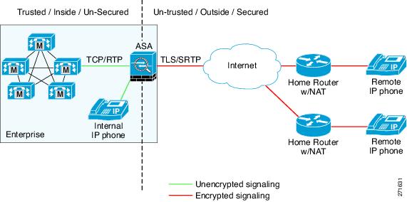
The phone proxy supports a Cisco UCM cluster in mixed mode or nonsecure mode. Regardless of the cluster mode, the remote phones that are capable of encryption are always forced to be in encrypted mode. TLS (signaling) and SRTP (media) are always terminated on the ASA. The ASA can also perform NAT, open pinholes for the media, and apply inspection policies for the SCCP and SIP protocols. In a nonsecure cluster mode or a mixed mode where the phones are configured as nonsecure, the phone proxy behaves in the following ways:
- The TLS connections from the phones are terminated on the ASA and a TCP connection is initiated to the Cisco UCM.
- SRTP sent from external IP phones to the internal network IP phone via the ASA is converted to RTP.
In a mixed mode cluster where the internal IP phones are configured as authenticated, the TLS connection is not converted to TCP to the Cisco UCM but the SRTP is converted to RTP.
In a mixed mode cluster where the internal IP phone is configured as encrypted, the TLS connection remains a TLS connection to the Cisco UCM and the SRTP from the remote phone remains SRTP to the internal IP phone.
Since the main purpose of the phone proxy is to make the phone behave securely while making calls to a nonsecure cluster, the phone proxy performs the following major functions:
- Creates the certificate trust list (CTL) file, which is used to perform certificate based authentication with remote phones.
- Modifies the IP phone configuration file when it is requested via TFTP, changes security fields from nonsecure to secure, and signs all files sent to the phone. These modifications secure remote phones by forcing the phones to perform encrypted signaling and media.
- Terminates TLS signaling from the phone and initiates TCP or TLS to Cisco UCM
- Inserts itself into the media path by modifying the Skinny and SIP signaling messages.
- Terminates SRTP and initiates RTP/SRTP to the called party.

Note![]() As an alternative to authenticating remote IP phones through the TLS handshake, you can configure authentication via LSC provisioning. With LSC provisioning you create a password for each remote IP phone user and each user enters the password on the remote IP phones to retrieve the LSC.
As an alternative to authenticating remote IP phones through the TLS handshake, you can configure authentication via LSC provisioning. With LSC provisioning you create a password for each remote IP phone user and each user enters the password on the remote IP phones to retrieve the LSC.
Because using LSC provisioning to authenticate remote IP phones requires the IP phones first register in nonsecure mode, Cisco recommends LSC provisioning be done inside the corporate network before giving the IP phones to end-users. Otherwise, having the IP phones register in nonsecure mode requires the Administrator to open the nonsecure signaling port for SIP and SCCP on the ASA.
See “Example 5: LSC Provisioning in Mixed-mode Cisco UCM cluster; Cisco UCM and TFTP Server on Publisher“. See also the Cisco Unified Communications Manager Security Guide for information on Using the Certificate Authority Proxy Function (CAPF) to install a locally significant certificate (LSC).
Supported Cisco UCM and IP Phones for the Phone Proxy
Cisco Unified Communications Manager
The following release of the Cisco Unified Communications Manager are supported with the phone proxy:
- Cisco Unified CallManager Version 4. x
- Cisco Unified CallManager Version 5.0
- Cisco Unified CallManager Version 5.1
- Cisco Unified Communications Manager 6.1
- Cisco Unified Communications Manager 7.0
- Cisco Unified Communications Manager 8.0
The phone proxy supports these IP phone features:
- Enterprise features like conference calls on remote phones connected through the phone proxy
- XML services
The following IP phones in the Cisco Unified IP Phones 7900 Series are supported with the phone proxy:
- Cisco Unified IP Phone 7975
- Cisco Unified IP Phone 7971
- Cisco Unified IP Phone 7970
- Cisco Unified IP Phone 7965
- Cisco Unified IP Phone 7962
- Cisco Unified IP Phone 7961
- Cisco Unified IP Phone 7961G-GE
- Cisco Unified IP Phone 7960 (SCCP protocol support only)
- Cisco Unified IP Phone 7945
- Cisco Unified IP Phone 7942
- Cisco Unified IP Phone 7941
- Cisco Unified IP Phone 7941G-GE
- Cisco Unified IP Phone 7940 (SCCP protocol support only)
- Cisco Unified Wireless IP Phone 7921
- Cisco Unified Wireless IP Phone 7925
Note![]() To support Cisco Unified Wireless IP Phone 7925, you must also configure MIC or LSC on the IP phone so that it properly works with the phone proxy.
To support Cisco Unified Wireless IP Phone 7925, you must also configure MIC or LSC on the IP phone so that it properly works with the phone proxy.
Note![]() The Cisco IP Communicator is supported with the phone proxy VLAN Traversal in authenticated TLS mode. We do not recommend it for remote access because SRTP/TLS is not supported currently on the Cisco IP Communicator.
The Cisco IP Communicator is supported with the phone proxy VLAN Traversal in authenticated TLS mode. We do not recommend it for remote access because SRTP/TLS is not supported currently on the Cisco IP Communicator.
Note![]() The ASA supports inspection of traffic from Cisco IP Phones running SCCP protocol version 19 and earlier.
The ASA supports inspection of traffic from Cisco IP Phones running SCCP protocol version 19 and earlier.
Licensing Requirements for the Phone Proxy
The Cisco Phone Proxy feature supported by the ASA require a Unified Communications Proxy license.
The following table shows the Unified Communications Proxy license details by platform:
Note![]() This feature is not available on No Payload Encryption models.
This feature is not available on No Payload Encryption models.
|
|
|
|---|---|
| Optional licenses: 24, 50, 100, 250, 500, 750, or 1000 sessions. |
|
| Optional licenses: 24, 50, 100, 250, 500, 750, 1000, or 2000 sessions. |
|
| Optional licenses: 24, 50, 100, 250, 500, 750, 1000, 2000, or 3000 sessions. |
|
| Optional licenses: 24, 50, 100, 250, 500, 750, 1000, 2000, 3000, 5000, or 10,000 sessions.2 |
|
| Optional licenses: 24, 50, 100, 250, 500, 750, or 1000 sessions. |
|
| Optional licenses: 24, 50, 100, 250, 500, 750, 1000, or 2000 sessions. |
|
| Optional licenses: 24, 50, 100, 250, 500, 750, 1000, 2000, or 3000 sessions. |
|
| Optional licenses: 24, 50, 100, 250, 500, 750, 1000, 2000, or 3000 sessions. |
|
| Optional licenses: 24, 50, 100, 250, 500, 750, 1000, 2000, 3000, 5000, or 10,000 sessions. 2 |
For more information about licensing, see Chapter4, “Managing Feature Licenses”
Prerequisites for the Phone Proxy
This section contains the following topics:
- Media Termination Instance Prerequisites
- Certificates from the Cisco UCM
- DNS Lookup Prerequisites
- Cisco Unified Communications Manager Prerequisites
- Access List Rules
- NAT and PAT Prerequisites
- Prerequisites for IP Phones on Multiple Interfaces
- 7960 and 7940 IP Phones Support
- Cisco IP Communicator Prerequisites
- Prerequisites for Rate Limiting TFTP Requests
- About ICMP Traffic Destined for the Media Termination Address
- End-User Phone Provisioning
Media Termination Instance Prerequisites
The ASA must have a media termination instance that meets the following criteria:
- You must configure one media termination for each phone proxy on the ASA. Multiple media termination instances on the ASA are not supported.
- For the media termination instance, you can configure a global media-termination address for all interfaces or configure a media-termination address for different interfaces. However, you cannot use a global media-termination address and media-termination addresses configured for each interface at the same time.
- If you configure a media termination address for multiple interfaces, you must configure an address on each interface that the ASA uses when communicating with IP phones.
For example, if you had three interfaces on the ASA (one internal interface and two external interfaces) and only one of the external interfaces were used to communicate with IP phones, you would configure two media termination addresses: one on the internal interface and one on the external interface that communicated with the IP phones.
- Only one media-termination address can be configured per interface.
- The IP addresses are publicly routable addresses that are unused IP addresses within the address range on that interface.
- The IP address on an interface cannot be the same address as that interface on the ASA.
- The IP addresses cannot overlap with existing static NAT pools or NAT rules.
- The IP addresses cannot be the same as the Cisco UCM or TFTP server IP address.
- For IP phones behind a router or gateway, you must also meet this prerequisite. On the router or gateway, add routes to the media termination address on the ASA interface that the IP phones communicate with so that the phone can reach the media termination address.
Certificates from the Cisco UCM
Import the following certificates which are stored on the Cisco UCM. These certificates are required by the ASA for the phone proxy.
If LSC provisioning is required or you have LSC enabled IP phones, you must import the CAPF certificate from the Cisco UCM. If the Cisco UCM has more than one CAPF certificate, you must import all of them to the ASA.
Note![]() You can configure LSC provisioning for additional end-user authentication. See the Cisco Unified Communications Manager configuration guide for information.
You can configure LSC provisioning for additional end-user authentication. See the Cisco Unified Communications Manager configuration guide for information.
See Importing Certificates from the Cisco UCM. For example, the CA Manufacturer certificate is required by the phone proxy to validate the IP phone certificate.
DNS Lookup Prerequisites
- If you have an fully qualified domain name (FQDN) configured for the Cisco UCM rather than an IP address, you must configure and enable DNS lookup on the ASA. For information about the dns domain-lookup command and how to use it to configure DNS lookup, see command reference.
- After configuring the DNS lookup, make sure that the ASA can ping the Cisco UCM with the configured FQDN.
- You must configure DNS lookup when you have a CAPF service enabled and the Cisco UCM is not running on the Publisher but the Publisher is configured with a FQDN instead of an IP address.
Cisco Unified Communications Manager Prerequisites
- The TFTP server must reside on the same interface as the Cisco UCM.
- The Cisco UCM can be on a private network on the inside but you need to have a static mapping for the Cisco UCM on the ASA to a public routable address.
- If NAT is required for Cisco UCM, it must be configured on the ASA, not on the existing firewall.
Access List Rules
If the phone proxy is deployed behind an existing firewall, access-list rules to permit signaling, TFTP requests, and media traffic to the phone proxy must be configured.
If NAT is configured for the TFTP server or Cisco UCMs, the translated “global” address must be used in the access lists.
Table 48-1 lists the ports that are required to be configured on the existing firewall:
|
|
|
|
|
|---|---|---|---|
Note![]() All these ports are configurable on the Cisco UCM, except for TFTP. These are the default values and should be modified if they are modified on the Cisco UCM. For example, 3804 is the default port for the CAPF Service. This default value should be modified if it is modified on the Cisco UCM.
All these ports are configurable on the Cisco UCM, except for TFTP. These are the default values and should be modified if they are modified on the Cisco UCM. For example, 3804 is the default port for the CAPF Service. This default value should be modified if it is modified on the Cisco UCM.
NAT and PAT Prerequisites
- If NAT is configured for the TFTP server, the NAT configuration must be configured prior to configuring the tftp-server command under the phone proxy.
- If NAT is configured for the TFTP server or Cisco UCMs, the translated “global” address must be used in the access lists.
- When the Skinny inspection global port is configured to use a non-default port, then you must configure the nonsecure port as the
global_sccp_port+443.
Therefore, if global_sccp_port is 7000, then the global secure SCCP port is 7443. Reconfiguring the port might be necessary when the phone proxy deployment has more than one Cisco UCM and they must share the interface IP address or a global IP address.
Note![]() Both PAT configurations—for the nonsecure and secure ports—must be configured.
Both PAT configurations—for the nonsecure and secure ports—must be configured.
Prerequisites for IP Phones on Multiple Interfaces
When IP phones reside on multiple interfaces, the phone proxy configuration must have the correct IP address set for the Cisco UCM in the CTL file.
See the following example topology for information about how to correctly set the IP address:
In this example topology, the following IP address are set:
- Cisco UCM on the inside interface is set to 10.0.0.5
- The DMZ network is 192.168.1.0/24
- The inside network is 10.0.0.0/24
The Cisco UCM is mapped with different global IP addresses from DMZ > outside and inside interfaces > outside interface.
In the CTL file, the Cisco UCM must have two entries because of the two different IP addresses. For example, if the static statements for the Cisco UCM are as follows:
There must be two CTL file record entries for the Cisco UCM:
7960 and 7940 IP Phones Support
- An LSC must be installed on these IP phones because they do not come pre installed with a MIC. Install the LSC on each phone before using them with the phone proxy to avoid opening the nonsecure SCCP port for the IP phones to register in nonsecure mode with the Cisco UCM.
See the following document for the steps to install an LSC on IP phones:
http://www.cisco.com/en/US/docs/voice_ip_comm/cucm/security/7_0_1/secugd/secucapf.html#wp1093518
Note![]() If an IP phone already has an LSC installed on it from a different Cisco UCM cluster, delete the LSC from the different cluster and install an LSC from the current Cisco UCM cluster.
If an IP phone already has an LSC installed on it from a different Cisco UCM cluster, delete the LSC from the different cluster and install an LSC from the current Cisco UCM cluster.
Note![]() You can configure LSC provisioning for additional end-user authentication. See the Cisco Unified Communications Manager configuration guide for information.
You can configure LSC provisioning for additional end-user authentication. See the Cisco Unified Communications Manager configuration guide for information.
- The CAPF certificate must be imported onto the ASA.
- The CTL file created on the ASA must be created with a CAPF record-entry.
- The phone must be configured to use only the SCCP protocol because the SIP protocol does not support encryption on these IP phones.
- If LSC provisioning is done via the phone proxy, you must add an ACL to allow the IP phones to register with the Cisco UCM on the nonsecure port 2000.
Cisco IP Communicator Prerequisites
To configure Cisco IP Communicator (CIPC) with the phone proxy, you must meet the following prerequisites:
- Include the cipc security-mode authenticated command under the phone-proxy command when configuring the phone proxy instance.
- Create an ACL to allow CIPC to register with the Cisco UCM in nonsecure mode.
- Configure null-sha1 as one of the SSL encryption ciphers.
Current versions of Cisco IP Communicator (CIPC) support authenticated mode and perform TLS signaling but not voice encryption. Therefore, you must include the following command when configuring the phone proxy instance:
cipc security-mode authenticated
Because CIPC requires an LSC to perform the TLS handshake, CIPC needs to register with the Cisco UCM in nonsecure mode using cleartext signaling. To allow the CIPC to register, create an ACL that allows the CIPC to connect to the Cisco UCM on the nonsecure SIP/SCCP signalling ports (5060/2000).
Note![]() You can configure LSC provisioning for additional end-user authentication. See the Cisco Unified Communications Manager configuration guide for information.
You can configure LSC provisioning for additional end-user authentication. See the Cisco Unified Communications Manager configuration guide for information.
CIPC uses a different cipher when doing the TLS handshake and requires the null-sha1 cipher and SSL encryption be configured. To add the null-shal cipher, use the show run all ssl command to see the output for the ssl encryption command and add null-shal to the end of the SSL encryption list.
Note![]() When used with CIPC, the phone proxy does not support end-users resetting their device name in CIPC (Preferences > Network tab > Use this Device Name field) or Administrators resetting the device name in Cisco Unified CM Administration console (Device menu > Phone Configuration > Device Name field). To function with the phone proxy, the CIPC configuration file must be in the format: SEP<mac_address>.cnf.xml. If the device name does not follow this format (SEP<mac_address>), CIPC cannot retrieve its configuration file from Cisco UMC via the phone proxy and CIPC will not function.
When used with CIPC, the phone proxy does not support end-users resetting their device name in CIPC (Preferences > Network tab > Use this Device Name field) or Administrators resetting the device name in Cisco Unified CM Administration console (Device menu > Phone Configuration > Device Name field). To function with the phone proxy, the CIPC configuration file must be in the format: SEP<mac_address>.cnf.xml. If the device name does not follow this format (SEP<mac_address>), CIPC cannot retrieve its configuration file from Cisco UMC via the phone proxy and CIPC will not function.
Prerequisites for Rate Limiting TFTP Requests
In a remote access scenario, we recommend that you configure rate limiting of TFTP requests because any IP phone connecting through the Internet is allowed to send TFTP requests to the TFTP server.
To configure rate limiting of TFTP requests, configure the police command in the Modular Policy Framework. See the command reference for information about using the police command.
Policing is a way of ensuring that no traffic exceeds the maximum rate (in bits/second) that you configure, thus ensuring that no one traffic flow can take over the entire resource. When traffic exceeds the maximum rate, the ASA drops the excess traffic. Policing also sets the largest single burst of traffic allowed.
Rate Limiting Configuration Example
The following example describes how you configure rate limiting for TFTP requests by using the police command and the Modular Policy Framework.
Begin by determining the conformance rate that is required for the phone proxy. To determine the conformance rate, use the following formula:
Y = size of each packet, which includes the L2, L3, and L4 plus the payload
Therefore, if a rate of 300 TFTP requests/second is required, then the conformance rate would be calculated as follows:
The example configuration below shows how the calculated conformance rate is used with the police command:
About ICMP Traffic Destined for the Media Termination Address
To control which hosts can ping the media termination address, use the icmp command and apply the access rule to the outside interface on the ASA.
Any rules for ICMP access applied to the outside interface apply to traffic destined for the media termination address.
For example, use the following command to deny ICMP pings from any host destined for the media termination address:
End-User Phone Provisioning
The phone proxy is a transparent proxy with respect to the TFTP and signaling transactions. If NAT is not configured for the Cisco UCM TFTP server, then the IP phones need to be configured with the Cisco UCM cluster TFTP server address.
If NAT is configured for the Cisco UCM TFTP server, then the Cisco UCM TFTP server global address is configured as the TFTP server address on the IP phones.
Ways to Deploy IP Phones to End Users
In both options, deploying a remote IP phone behind a commercial Cable/DSL router with NAT capabilities is supported.
Stage the IP phones at corporate headquarters before sending them to the end users:
- The phones register inside the network. IT ensures there are no issues with the phone configurations, image downloads, and registration.
- If Cisco UCM cluster was in mixed mode, the CTL file should be erased before sending the phone to the end user.
Advantages of this option are:
- Easier to troubleshoot and isolate problems with the network or phone proxy because you know whether the phone is registered and working with the Cisco UCM.
- Better user experience because the phone does not have to download firmware from over a broadband connection, which can be slow and require the user to wait for a longer time.
Send the IP phone to the end user. When using option 2, the user must be provided instructions to change the settings on phones with the appropriate Cisco UCM and TFTP server IP address.
Note![]() As an alternative to authenticating remote IP phones through the TLS handshake, you can configure authentication via LSC provisioning. With LSC provisioning you create a password for each remote IP phone user and each user enters the password on the remote IP phones to retrieve the LSC.
As an alternative to authenticating remote IP phones through the TLS handshake, you can configure authentication via LSC provisioning. With LSC provisioning you create a password for each remote IP phone user and each user enters the password on the remote IP phones to retrieve the LSC.
Because using LSC provisioning to authenticate remote IP phones requires the IP phones first register in nonsecure mode, Cisco recommends LSC provisioning be done inside the corporate network before giving the IP phones to end-users. Otherwise, having the IP phones register in nonsecure mode requires the Administrator to open the nonsecure signaling port for SIP and SCCP on the ASA.
See “Example 5: LSC Provisioning in Mixed-mode Cisco UCM cluster; Cisco UCM and TFTP Server on Publisher“. See also the Cisco Unified Communications Manager Security Guide for information on Using the Certificate Authority Proxy Function (CAPF) to install a locally significant certificate (LSC).
Phone Proxy Guidelines and Limitations
This section includes the following topics:
General Guidelines and Limitations
The phone proxy has the following general limitations:
- Only one phone proxy instance can be configured on the ASA by using the phone-proxy command. See the command reference for information about the phone-proxy command. See also Creating the Phone Proxy Instance.
- The phone proxy only supports one Cisco UCM cluster. See Creating the CTL File for the steps to configure the Cisco UCM cluster for the phone proxy.
- The phone proxy is not supported when the ASA is running in transparent mode or multiple context mode.
- When a remote IP phone calls an invalid internal or external extension, the phone proxy does not support playing the annunciator message from the Cisco UCM. Instead, the remote IP phone plays a fast busy signal instead of the annunciator message "Your call cannot be completed..." However, when an internal IP phone dials in invalid extension, the annunciator messages plays "Your call cannot be completed..."
- Packets from phones connecting to the phone proxy over a VPN tunnel are not inspected by the ASA inspection engines.
- The phone proxy does not support IP phones sending Real-Time Control Protocol (RTCP) packets through the ASA. Disable RTCP packets in the Cisco Unified CM Administration console from the Phone Configuration page. See your Cisco Unified Communications Manager (CallManager) documentation for information about setting this configuration option.
- When used with CIPC, the phone proxy does not support end-users resetting their device name in CIPC (Preferences > Network tab > Use this Device Name field) or Administrators resetting the device name in Cisco Unified CM Administration console (Device menu > Phone Configuration > Device Name field). To function with the phone proxy, the CIPC configuration file must be in the format: SEP<mac_address>.cnf.xml. If the device name does not follow this format (SEP<mac_address>), CIPC cannot retrieve its configuration file from Cisco UMC via the phone proxy and CIPC will not function.
- The phone proxy does not support IP phones sending SCCP video messages using Cisco VT Advantage because SCCP video messages do not support SRTP keys.
- For mixed-mode clusters, the phone proxy does not support the Cisco Unified Call Manager using TFTP to send encrypted configuration files to IP phones through the ASA.
- Multiple IP phones behind one NAT device must be configured to use the same security mode.
When the phone proxy is configured for a mixed-mode cluster and multiple IP phones are behind one NAT device and registering through the phone proxy, all the SIP and SCCP IP phones must be configured as authenticated or encrypted, or all as non-secure on the Unified Call Manager.
For example, if there are four IP phones behind one NAT device where two IP phones are configured using SIP and two IP phones are configured using SCCP, the following configurations on the Unified Call Manager are acceptable:
–![]() Two SIP IP phones: one IP phone in authenticated mode and one in encrypted mode, both in authenticated mode, or both in encrypted mode
Two SIP IP phones: one IP phone in authenticated mode and one in encrypted mode, both in authenticated mode, or both in encrypted mode
Two SCCP IP phones: one IP phone in authenticated mode and one in encrypted mode, both in authenticated mode, or both in encrypted mode
–![]() Two SIP IP phones: both in non-secure mode
Two SIP IP phones: both in non-secure mode
Two SCCP IP phones: one IP phone in authenticated mode and one in encrypted mode, both in authenticated mode, both in encrypted mode
–![]() Two SIP IP phones: one IP phone in authenticated mode and one in encrypted mode, both in authenticated mode, both in encrypted mode
Two SIP IP phones: one IP phone in authenticated mode and one in encrypted mode, both in authenticated mode, both in encrypted mode
Two SCCP IP phones: both in non-secure mode
This limitation results from the way the application-redirect rules (rules that convert TLS to TCP) are created for the IP phones.
Media Termination Address Guidelines and Limitations
The phone proxy has the following limitations relating to configuring the media-termination address:
- When configuring the media-termination address, the phone proxy does not support having internal IP phones (IP phones on the inside network) being on a different network interface from the Cisco UCM unless the IP phones are forced to use the non-secure Security mode.
When internal IP phones are on a different network interface than the Cisco UCM, the IP phones signalling sessions still go through ASA; however, the IP phone traffic does not go through the phone proxy. Therefore, Cisco recommends that you deploy internal IP phones on the same network interface as the Cisco UMC.
If the Cisco UMC and the internal IP phones must be on different network interfaces, you must add routes for the internal IP phones to access the network interface of the media-termination address where Cisco UMC resides.
When the phone proxy is configured to use a global media-termination address, all IP phones see the same global address, which is a public routable address.
- If you decide to configure a media-termination address on interfaces (rather than using a global interface), you must configure a media-termination address on at least two interfaces (the inside and an outside interface) before applying the phone-proxy service policy. Otherwise, you will receive an error message when enabling the Phone Proxy with SIP and Skinny Inspection.
- The phone proxy can use only one type of media termination instance at a time; for example, you can configure a global media-termination address for all interfaces or configure a media-termination address for different interfaces. However, you cannot use a global media-termination address and media-termination addresses configured for each interface at the same time.
Configuring the Phone Proxy
This section includes the following topics:
- Task Flow for Configuring the Phone Proxy in a Non-secure Cisco UCM Cluster
- Importing Certificates from the Cisco UCM
- Task Flow for Configuring the Phone Proxy in a Mixed-mode Cisco UCM Cluster
- Creating Trustpoints and Generating Certificates
- Creating the CTL File
- Using an Existing CTL File
- Creating the TLS Proxy Instance for a Non-secure Cisco UCM Cluster
- Creating the TLS Proxy for a Mixed-mode Cisco UCM Cluster
- Creating the Media Termination Instance
- Creating the Phone Proxy Instance
- Enabling the Phone Proxy with SIP and Skinny Inspection
- Configuring Linksys Routers with UDP Port Forwarding for the Phone Proxy
Task Flow for Configuring the Phone Proxy in a Non-secure Cisco UCM Cluster
Follow these tasks to configure the phone proxy in a Non-secure Cisco UCM Cluster:
Step 1![]() Create trustpoints and generate certificates for each entity in the network (Cisco UCM, Cisco UCM and TFTP, TFTP server, CAPF) that the IP phone must trust. The certificates are used in creating the CTL file. See Creating Trustpoints and Generating Certificates.
Create trustpoints and generate certificates for each entity in the network (Cisco UCM, Cisco UCM and TFTP, TFTP server, CAPF) that the IP phone must trust. The certificates are used in creating the CTL file. See Creating Trustpoints and Generating Certificates.
Note![]() Before you create the trustpoints and generate certificates, you must have imported the required certificates, which are stored on the Cisco UCM. See Certificates from the Cisco UCM and Importing Certificates from the Cisco UCM
Before you create the trustpoints and generate certificates, you must have imported the required certificates, which are stored on the Cisco UCM. See Certificates from the Cisco UCM and Importing Certificates from the Cisco UCM
Step 2![]() Create the CTL file for the phone proxy. See Creating the CTL File.
Create the CTL file for the phone proxy. See Creating the CTL File.
Step 3![]() Create the TLS proxy instance. See Creating the TLS Proxy Instance for a Non-secure Cisco UCM Cluster.
Create the TLS proxy instance. See Creating the TLS Proxy Instance for a Non-secure Cisco UCM Cluster.
Step 4![]() Create the media termination instance for the phone proxy. See Creating the Media Termination Instance.
Create the media termination instance for the phone proxy. See Creating the Media Termination Instance.
Step 5![]() Create the phone proxy instance. See Creating the Phone Proxy Instance.
Create the phone proxy instance. See Creating the Phone Proxy Instance.
Step 6![]() Enable the phone proxy y with SIP and Skinny inspection. See Enabling the Phone Proxy with SIP and Skinny Inspection.
Enable the phone proxy y with SIP and Skinny inspection. See Enabling the Phone Proxy with SIP and Skinny Inspection.
Importing Certificates from the Cisco UCM
For the TLS proxy used by the phone proxy to complete the TLS handshake successfully, it needs to verify the certificates from the IP phone (and the Cisco UCM if doing TLS with Cisco UCM). To validate the IP phone certificate, we need the CA Manufacturer certificate which is stored on the Cisco UCM. Follow these steps to import the CA Manufacturer certificate to the ASA.
Step 1![]() Go to the Cisco UCM Operating System Administration web page.
Go to the Cisco UCM Operating System Administration web page.
Step 2![]() Choose Security > Certificate Management.
Choose Security > Certificate Management.
Note![]() Earlier versions of Cisco UCM have a different UI and way to locate the certificates. For example, in Cisco UCM version 4.x, certificates are located in the directory
Earlier versions of Cisco UCM have a different UI and way to locate the certificates. For example, in Cisco UCM version 4.x, certificates are located in the directory C:\Program Files\Cisco\Certificates. See your Cisco Unified Communications Manager (CallManager) documentation for information about locating certificates.
Step 3![]() Click Find and it will display all the certificates.
Click Find and it will display all the certificates.
Step 4![]() Find the filename
Find the filename Cisco_Manufacturing_CA. This is the certificate need to verify the IP phone certificate. Click the.PEM file Cisco_Manufacturing_CA.pem. This will show you the certificate information and a dialog box that has the option to download the certificate.
Note![]() If the certificate list contains more than one certificate with the filename
If the certificate list contains more than one certificate with the filename Cisco_Manufacturing_CA, make you select the certificate Cisco_Manufacturing_CA.pem—the one with the.pem file extension.
Step 5![]() Click Download and save the file as a text file.
Click Download and save the file as a text file.
Step 6![]() On the ASA, create a trustpoint for the Cisco Manufacturing CA and enroll via terminal by entering the following commands. Enroll via terminal because you will paste the certificate you downloaded in Step 4.
On the ASA, create a trustpoint for the Cisco Manufacturing CA and enroll via terminal by entering the following commands. Enroll via terminal because you will paste the certificate you downloaded in Step 4.
Step 7![]() Authenticate the trustpoint by entering the following command:
Authenticate the trustpoint by entering the following command:
Step 8![]() You are prompted to “Enter the base 64 encoded CA Certificate.” Copy the.PEM file you downloaded in Step 4 and paste it at the command line. The file is already in base-64 encoding so no conversion is required. If the certificate is OK, you are prompted to accept it: “Do you accept this certificate? [yes/no].” Enter yes.
You are prompted to “Enter the base 64 encoded CA Certificate.” Copy the.PEM file you downloaded in Step 4 and paste it at the command line. The file is already in base-64 encoding so no conversion is required. If the certificate is OK, you are prompted to accept it: “Do you accept this certificate? [yes/no].” Enter yes.
Note![]() When you copy the certificate, make sure that you also copy also the lines with BEGIN and END.
When you copy the certificate, make sure that you also copy also the lines with BEGIN and END.

Tip If the certificate is not ok, use the debug crypto ca command to show debug messages for PKI activity (used with CAs).
Step 9![]() Repeat the Step 1 through Step 8 for the next certificate. Table 48-2 shows the certificates that are required by the ASA.
Repeat the Step 1 through Step 8 for the next certificate. Table 48-2 shows the certificates that are required by the ASA.
Task Flow for Configuring the Phone Proxy in a Mixed-mode Cisco UCM Cluster
Note![]() For mixed-mode clusters, the phone proxy does not support the Cisco Unified Call Manager using TFTP to send encrypted configuration files to IP phones through the ASA.
For mixed-mode clusters, the phone proxy does not support the Cisco Unified Call Manager using TFTP to send encrypted configuration files to IP phones through the ASA.
Follow these tasks to configure the phone proxy in a Non-secure Cisco UCM Cluster:
Step 1![]() Create trustpoints and generate certificates for each entity in the network (Cisco UCM, Cisco UCM and TFTP, TFTP server, CAPF) that the IP phone must trust. The certificates are used in creating the CTL file. See Creating Trustpoints and Generating Certificates.
Create trustpoints and generate certificates for each entity in the network (Cisco UCM, Cisco UCM and TFTP, TFTP server, CAPF) that the IP phone must trust. The certificates are used in creating the CTL file. See Creating Trustpoints and Generating Certificates.
Note![]() Before you create the trustpoints and generate certificates, you must have imported the required certificates, which are stored on the Cisco UCM. See Certificates from the Cisco UCM and Importing Certificates from the Cisco UCM
Before you create the trustpoints and generate certificates, you must have imported the required certificates, which are stored on the Cisco UCM. See Certificates from the Cisco UCM and Importing Certificates from the Cisco UCM
Step 2![]() Create the CTL file for the phone proxy. See Creating the CTL File.
Create the CTL file for the phone proxy. See Creating the CTL File.
Note![]() When the phone proxy is being configured to run in mixed-mode clusters, you have the following option to use an existing CTL file to install the trustpoints. See Using an Existing CTL File.
When the phone proxy is being configured to run in mixed-mode clusters, you have the following option to use an existing CTL file to install the trustpoints. See Using an Existing CTL File.
Step 3![]() Create the TLS proxy instance. See Creating the TLS Proxy for a Mixed-mode Cisco UCM Cluster.
Create the TLS proxy instance. See Creating the TLS Proxy for a Mixed-mode Cisco UCM Cluster.
Step 4![]() Create the media termination instance for the phone proxy. See Creating the Media Termination Instance.
Create the media termination instance for the phone proxy. See Creating the Media Termination Instance.
Step 5![]() Create the phone proxy instance. See Creating the Phone Proxy Instance.
Create the phone proxy instance. See Creating the Phone Proxy Instance.
Step 6![]() While configuring the phone proxy instance (in the Phone Proxy Configuration mode), enter the following command to configure the mode of the cluster to be mixed mode because the default is nonsecure:
While configuring the phone proxy instance (in the Phone Proxy Configuration mode), enter the following command to configure the mode of the cluster to be mixed mode because the default is nonsecure:
Step 7![]() Enable the phone proxy y with SIP and Skinny inspection. See Enabling the Phone Proxy with SIP and Skinny Inspection.
Enable the phone proxy y with SIP and Skinny inspection. See Enabling the Phone Proxy with SIP and Skinny Inspection.
Creating Trustpoints and Generating Certificates
Create trustpoints and generate certificates for each entity in the network (Cisco UCM, Cisco UCM and TFTP, TFTP server, CAPF) that the IP phone must trust. The certificates are used in creating the CTL file.
You need to create trustpoints for each Cisco UCM (primary and secondary if a secondary Cisco UCM is used) and TFTP server in the network. The trustpoints need to be in the CTL file for the phones to trust the Cisco UCM.
Import the required certificates, which are stored on the Cisco UCM. See Certificates from the Cisco UCM and Importing Certificates from the Cisco UCM.
|
|
|
|
|---|---|---|
|
|
||
|
|
Creates the trustpoints for each entity in the network (primary Cisco UCM, secondary Cisco UCM, and TFTP server). Note You are only required to create a separate trustpoint for the TFTP server when the TFTP server resides on a different server from the Cisco UCM. See Example 3: Mixed-mode Cisco UCM cluster, Cisco UCM and TFTP Server on Different Servers for an example of this configuration. |
|
|
|
||
|
|
||
|
|
||
|
|
Requests the certificate from the CA server and causes the ASA to generate the certificate. When prompted to include the device serial number in the subject name, type Y to include the serial number or type N to exclude it. When prompted to generate the self-signed certificate, type Y. |
Once you have created the trustpoints and generated the certificates, create the CTL file for the phone proxy. See Creating the CTL File.
If you are configuring the phone proxy in a mixed-mode cluster, you can use an existing CTL file. See Using an Existing CTL File.
Creating the CTL File
Create the CTL file that will be presented to the IP phones during the TFTP requests.
If you are using domain names for your Cisco UCM and TFTP server, you must configure DNS lookup on the ASA. Add an entry for each of the outside interfaces on the ASA into your DNS server, if such entries are not already present. Each ASA outside IP address should have a DNS entry associated with it for lookups. These DNS entries must also be enabled for Reverse Lookup.
Enable DNS lookups on your ASA with the dns domain-lookup interface_name command (where the interface_name specifies the interface that has a route to your DNS server). Additionally, define your DNS server IP address on the ASA; for example: dns name-server 10.2.3.4 (IP address of your DNS server).
Note![]() You can enter the dns domain-lookup command multiple times to enable DNS lookup on multiple interfaces. If you enter multiple commands, the ASA tries each interface in the order it appears in the configuration until it receives a response.
You can enter the dns domain-lookup command multiple times to enable DNS lookup on multiple interfaces. If you enter multiple commands, the ASA tries each interface in the order it appears in the configuration until it receives a response.
See the command reference for information about the dns domain-lookup command.
Once you have configured the CTL file for the phone proxy, create the TLS proxy instance. See Creating the TLS Proxy Instance for a Non-secure Cisco UCM Cluster to add the TLS proxy when configuring the phone proxy in a non-secure mode or see Creating the TLS Proxy for a Mixed-mode Cisco UCM Cluster if the phone proxy is running in a mixed-mode cluster.
Using an Existing CTL File
Note![]() Only when the phone proxy is running in mixed-mode clusters, you have the option to use an existing CTL file to install trustpoints.
Only when the phone proxy is running in mixed-mode clusters, you have the option to use an existing CTL file to install trustpoints.
If you have an existing CTL file that contains the correct IP addresses of the entities (namely, the IP address that the IP phones use for the Cisco UCM or TFTP servers), you can be use it to create a new CTL file thereby using the existing CTL file to install the trustpoints for each entity in the network (Cisco UCM, Cisco UCM and TFTP, TFTP server, CAPF) that the IP phones must trust.
If a CTL file exists for the cluster, copy the CTL file to Flash memory. When you copy the CTL file to Flash memory, rename the file and do not name the file CTLFile.tlv.
If you are using domain names for your Cisco UCM and TFTP server, you must configure DNS lookup on the ASA. See the prerequisites for Creating the CTL File.
When using an existing CTL file to configure the phone proxy, you can add additional entries to the file as necessary. See Creating the CTL File.
Once you have configured the CTL file for the phone proxy, create the TLS proxy instance. See Creating the TLS Proxy Instance for a Non-secure Cisco UCM Cluster to add the TLS proxy when configuring the phone proxy in a non-secure mode or see Creating the TLS Proxy for a Mixed-mode Cisco UCM Cluster if the phone proxy is running in a mixed-mode cluster.
Creating the TLS Proxy Instance for a Non-secure Cisco UCM Cluster
Create the TLS proxy instance to handle the encrypted signaling.
Once you have created the TLS proxy instance, create the phone proxy instance. See Creating the Phone Proxy Instance.
Creating the TLS Proxy for a Mixed-mode Cisco UCM Cluster
For mixed mode clusters, there might be IP phones that are already configured as encrypted so it requires TLS to the Cisco UCM. You must configure the LDC issuer for the TLS proxy.
|
|
|
|
|---|---|---|
|
|
Creates the necessary RSA key pairs. Where the key-pair-label is the LDC signer key and the key for the IP phones. |
|
|
|
Creates an internal local CA to sign the LDC for Cisco IP phones. |
|
|
|
||
|
|
Defines the local CA role for the trustpoint to issue dynamic certificates for the TLS proxy. |
|
|
|
Includes the indicated FQDN in the Subject Alternative Name extension of the certificate during enrollment. |
|
|
|
Includes the indicated subject DN in the certificate during enrollment Where the X.500_name is for the LDC. Use commas to separate attribute-value pairs. Insert quotation marks around any value that contains commas or spaces. |
|
|
|
||
|
|
||
|
|
||
|
|
Configures the server trustpoint and references the internal trustpoint named _internal_PP _ctl-instance_filename. |
|
|
|
Specifies the local CA trustpoint to issue client dynamic certificates. |
|
|
|
Specifies the RSA keypair to be used by client dynamic certificates. |
|
|
|
Options include des-sha1, 3des-sha1, aes128-sha1, aes256-sha1, or null-sha1. |
|
Exports the local CA certificate and installs it as a trusted certificate on the Cisco Unified Communications Manager server by performing one of the following actions. |
||
|
|
|
Exports the certificate if a trustpoint with proxy-ldc-issuer is used as the signer of the dynamic certificates. |
|
|
|
Exports the certificate for the embedded local CA server LOCAL-CA-SERVER. After exporting the certificate, you must save the output to a file and import it on the Cisco Unified Communications Manager. You can use the Display Certificates function in the Cisco Unified Communications Manager software to verify the installed certificate. For information about performing these procedures, see the following URLs: http://www.cisco.com/en/US/docs/voice_ip_comm/cucm/cucos/5_0_4/iptpch6.html#wp1040848 http://www.cisco.com/en/US/docs/voice_ip_comm/cucm/cucos/5_0_4/iptpch6.html#wp1040354 |
Once you have created the TLS proxy instance and installed the certificate on the Cisco Unified Communications Manager, create the phone proxy instance. See Creating the Phone Proxy Instance.
Creating the Media Termination Instance
Create the media termination instance that you will use in the phone proxy.
The media termination address you configure must meet the requirements as described in Media Termination Instance Prerequisites.
|
|
|
|
|---|---|---|
|
|
Creates the media termination instance that you attach to the phone proxy. |
|
|
|
Configures the media-termination address used by the media termination instance. The phone proxy uses this address for SRTP and RTP. For the media termination instance, you can configure a global media-termination address for all interfaces or configure a media-termination address for different interfaces. However, you cannot use a global media-termination address and media-termination addresses configured for each interface at the same time. If you configure a media termination address for multiple interfaces, you must configure an address on each interface that the ASA uses when communicating with IP phones. The IP addresses are publicly routable addresses that are unused IP addresses within the address range on that interface. See Media Termination Instance Prerequisites for the complete list of prerequisites that you must follow when creating the media termination instance and configuring the media termination addresses. |
|
|
|
Specifies the minimum and maximum values for the RTP port range for the media termination instance. |
Once you have created the media termination instance, create the phone proxy instance. See Creating the Phone Proxy Instance.
Creating the Phone Proxy Instance
Create the phone proxy instance.
You must have already created the CTL file and TLS proxy instance for the phone proxy.
See Creating the CTL File and Creating the TLS Proxy Instance for a Non-secure Cisco UCM Cluster
|
|
|
|
|---|---|---|
|
|
Creates the phone proxy instance. Only one phone proxy instance can be configured on the security appliance. |
|
|
|
Specifies the media termination instance used by the phone proxy for SRTP and RTP. Note You must create the media termination instance before you specify it in the phone proxy instance. See Creating the Media Termination Instance for the steps to create the media termination instance. |
|
|
|
Creates the TFTP server using the actual internal address and specify the interface on which the TFTP server resides. |
|
|
|
Configures the TLS proxy instance that you have already created. |
|
|
|
Configures the CTL file instance that you have already created, |
|
|
|
(Optional) If the operational environment has an external HTTP proxy to which the IP phones direct all HTTP request, configures a proxy server. You can configure only one proxy server while the phone proxy is in use. By default, the Phone URL Parameters configured under the Enterprise Parameters use an FQDN in the URLs. The parameters might need to be changed to use an IP address if the DNS lookup for the HTTP proxy does not resolve the FQDNs. Note If the IP phones have already downloaded their configuration files after you have configured the proxy server, you must restart the IP phones so that they get the configuration file with the proxy server address in the file. |
|
|
|
(Optional) Forces Cisco IP Communicator (CIPC) softphones to operate in authenticated mode when CIPC softphones are deployed in a voice and data VLAN scenario. See Cisco IP Communicator Prerequisites for all requirements for using the phone proxy with CIPC. |
|
|
|
(Optional) Preserve the settings configured on the Cisco UCM for each IP phone configured. By default, the following settings are disabled on the IP phones: |
Once you have created the phone proxy instance, configuring SIP and Skinny for the phone proxy. See Enabling the Phone Proxy with SIP and Skinny Inspection.
Enabling the Phone Proxy with SIP and Skinny Inspection
Enables the phone proxy instance that you created to inspect SIP and Skinny protocol traffic.
You must have already created the phone proxy instance. See Creating the Phone Proxy Instance.
Configuring Linksys Routers with UDP Port Forwarding for the Phone Proxy
When IP phones are behind a NAT-capable router, the router can be configured to forward the UDP ports to the IP address of the IP phone. Specifically, configure the router for UDP port forwarding when an IP phone is failing during TFTP requests and the failure is due to the router dropping incoming TFTP data packets. Configure the router to enable UDP port forwarding on port 69 to the IP phone.
As an alternative of explicit UDP forwarding, some Cable/DSL routers require you to designate the IP phone as a DMZ host. For Cable/DSL routers, this host is a special host that receives all incoming connections from the public network.
When configuring the phone proxy, there is no functional difference between an IP phone that has UDP ports explicitly forwarded or an IP phone designated as a DMZ host. The choice is entirely dependent upon the capabilities and preference of the end user.
Configuring Your Router
Your firewall/router needs to be configured to forward a range of UDP ports to the IP phone. This will allow the IP phone to receive audio when you make/receive calls.
Note![]() Different Cable/DSL routers have different procedures for this configuration. Furthermore most NAT-capable routers will only allow a given port range to be forwarded to a single IP address
Different Cable/DSL routers have different procedures for this configuration. Furthermore most NAT-capable routers will only allow a given port range to be forwarded to a single IP address
The configuration of each brand/model of firewall/router is different, but the task is the same. For specific instructions for your brand and model of router, please contact the manufacturer’s website.
Step 1![]() From your web browser, connect to the router administrative web page. For Linksys, this is typically something like
From your web browser, connect to the router administrative web page. For Linksys, this is typically something like http://192.168.1.1.
Step 2![]() Click Applications & Gaming or the Port Forwarding tab (whichever is present on your router).
Click Applications & Gaming or the Port Forwarding tab (whichever is present on your router).
Step 3![]() Locate the table containing the port forwarding data and add an entry containing the following values:
Locate the table containing the port forwarding data and add an entry containing the following values:
|
|
|
|
|
|
|
|---|---|---|---|---|---|
Step 4![]() Click Save Settings. Port forwarding is configured.
Click Save Settings. Port forwarding is configured.
Troubleshooting the Phone Proxy
This section includes the following topics:
- Debugging Information from the Security Appliance
- Debugging Information from IP Phones
- IP Phone Registration Failure
- Media Termination Address Errors
- Audio Problems with IP Phones
- Saving SAST Keys
Debugging Information from the Security Appliance
This section describes how to use the debug, capture, and show commands to obtain debugging information for the phone proxy. See the command reference for detailed information about the syntax for these commands.
Table 48-4 lists the debug commands to use with the phone proxy.
Table 48-5 lists the capture commands to use with the phone proxy. Use the capture command on the appropriate interfaces (IP phones and Cisco UCM) to enable packet capture capabilities for packet sniffing and network fault isolation.
Table 48-6 lists the show commands to use with the phone proxy.
|
|
|
|
|---|---|---|
To show the packets or connections dropped by the accelerated security path. |
Use this command to troubleshoot audio quality issues with the IP phones or other traffic issues with the phone proxy. In addition to running this command, get call status from the phone to check for any dropped packets or jitter. See Debugging Information from IP Phones. |
|
To show the classifier contents of the accelerated security path for the specific classifier domain. |
If the IP phones are not downloading TFTP files, use this command to check that the classification rule for the domain If the IP phones are failing to register, use this command to make sure there is a classification rule for the domain |
|
To show the connections that are to the ASA or from the ASA, in addition to through-traffic connections. |
If you are experiencing problems with audio, use this command to make sure that there are connections opened from the IP phone to the media termination address. Using this command shows that the phone proxy has connections that are going through “inspect-phone-proxy”, which inspects TFTP connections. Using this command verifies that the TFTP requests are being inspected because the p flag is there. |
|
Before entering the show logging command, enable the logging buffered command so that the show logging command displays the current message buffer and the current settings. Use this command to determine if the phone proxy and IP phones are successfully completing the TLS handshake. Note Using the show logging command is useful for troubleshooting many problems where packets might be denied or there are translation failures. |
||
To show the corresponding media sessions stored by the phone proxy. |
Use this command to display output from successful calls. Additionally, use this command to troubleshoot problems with IP phone audio, such as one-way audio. |
|
To show the IP phones capable of Secure mode stored in the database. |
For any problems, make sure there is an entry for the IP phone in this output and that the port for this IP phone is non-zero, which indicates that it has successfully registered with the Cisco UCM. |
|
To show the corresponding signaling sessions stored by the phone proxy. |
Use this command to troubleshoot media or signaling failure. |
|
To show active TLS proxy sessions related to the phone proxy. |
If the IP phone has failed to register, use this command to see if the IP phone has successfully completed the handshake with the TLS proxy configured for the phone proxy. |
Debugging Information from IP Phones
On the IP phone, perform the following actions:
- Check the Status messages on the IP phone by selecting the Settings button > Status > Status Messages and selecting the status item that you want to view.
- Collect the call-statistics data from the IP phone by selecting the Settings button > Status > Call Statistic. Data like the following displays:
- Check the Security settings on the IP phone by selecting the Settings button > Security Configuration. Settings for web access, Security mode, MIC, LSC, CTL file, trust list, and CAPF appear. Under Security mode, make sure the IP phone is set to Encrypted.
- Check the IP phone to determine which certificates are installed on the phone by selecting the Settings button > Security Configuration > Trust List. In the trustlist, verify the following:
–![]() Make sure that there is an entry for each entity that the IP phone will need to contact. If there is a primary and backup Cisco UCM, the trustlist should contain entries for each Cisco UCM.
Make sure that there is an entry for each entity that the IP phone will need to contact. If there is a primary and backup Cisco UCM, the trustlist should contain entries for each Cisco UCM.
–![]() If the IP phone needs an LSC, the record entry should contain a CAPF entry.
If the IP phone needs an LSC, the record entry should contain a CAPF entry.
–![]() Make sure that the IP addresses listed for each entry are the mapped IP addresses of the entities that the IP phone can reach.
Make sure that the IP addresses listed for each entry are the mapped IP addresses of the entities that the IP phone can reach.
IP Phone Registration Failure
The following errors can make IP phones unable to register with the phone proxy:
- TFTP Auth Error Displays on IP Phone Console
- Configuration File Parsing Error
- Configuration File Parsing Error: Unable to Get DNS Response
- Non-configuration File Parsing Error
- Cisco UCM Does Not Respond to TFTP Request for Configuration File
- IP Phone Does Not Respond After the Security Appliance Sends TFTP Data
- IP Phone Requesting Unsigned File Error
- IP Phone Unable to Download CTL File
- IP Phone Registration Failure from Signaling Connections
- SSL Handshake Failure
- Certificate Validation Errors
TFTP Auth Error Displays on IP Phone Console
Problem The IP phone displays the following Status message:
Solution This Status message can indicate a problem with the IP phone CTL file.
To correct problems with the IP phone CTL file, perform the following:
Step 1![]() From the IP phone, select the Setting button > Security Configuration > Trust List. Verify that each entity in the network—Primary Cisco UCM, Secondary Cisco UCM, TFTP server—has its own entry in the trustlist and that each entity IP address is reachable by the IP phone.
From the IP phone, select the Setting button > Security Configuration > Trust List. Verify that each entity in the network—Primary Cisco UCM, Secondary Cisco UCM, TFTP server—has its own entry in the trustlist and that each entity IP address is reachable by the IP phone.
Step 2![]() From the ASA, verify that the CTL file for the phone proxy contains one record entry for each entity in the network—Primary Cisco UCM, Secondary Cisco UCM, TFTP server—by entering the following command:
From the ASA, verify that the CTL file for the phone proxy contains one record entry for each entity in the network—Primary Cisco UCM, Secondary Cisco UCM, TFTP server—by entering the following command:
Each of these record entries creates one entry on the IP phone trustlist. The phone proxy creates one entry internally with the function CUCM+TFTP.
Step 3![]() In the CTL file, verify that each IP address is the global or mapped IP address of the entity. If the IP phones are on multiple interfaces, additional addressing requirements apply. See Prerequisites for IP Phones on Multiple Interfaces.
In the CTL file, verify that each IP address is the global or mapped IP address of the entity. If the IP phones are on multiple interfaces, additional addressing requirements apply. See Prerequisites for IP Phones on Multiple Interfaces.
Configuration File Parsing Error
Problem When the ASA receives the configuration file from the Cisco UCM and tries to parse it, the following error appears in the debug output ( debug phone-proxy tftp errors):
Solution Perform the following actions to troubleshoot this problem:
Step 1![]() Enter the following URL in a web browser to obtain the IP phone configuration file from the Cisco Unified CM Administration console:
Enter the following URL in a web browser to obtain the IP phone configuration file from the Cisco Unified CM Administration console:
For example, if the Cisco UCM IP address is 128.106.254.2 and the IP phone configuration file name is SEP000100020003.cnf.xml, enter:
Step 2![]() Save this file, open a case with TAC and send them this file and the output from running the debug phone-proxy tftp command on the ASA.
Save this file, open a case with TAC and send them this file and the output from running the debug phone-proxy tftp command on the ASA.
Configuration File Parsing Error: Unable to Get DNS Response
Problem When the ASA receives the configuration file from the Cisco UCM and tries to parse it, the following error appears in the debug output ( debug phone-proxy tftp errors):
The error indicates that the Cisco UCM is configured as an FQDN and the phone proxy is trying to do a DNS lookup but failed to get a response.
Step 1![]() Verify that DNS lookup is configured on the ASA.
Verify that DNS lookup is configured on the ASA.
Step 2![]() If DNS lookup is configured, determine whether you can ping the FQDN for the Cisco UCM from the ASA.
If DNS lookup is configured, determine whether you can ping the FQDN for the Cisco UCM from the ASA.
Step 3![]() If ASA cannot ping the Cisco UCM FQDN, check to see if there is a problem with the DNS server.
If ASA cannot ping the Cisco UCM FQDN, check to see if there is a problem with the DNS server.
Step 4![]() Additionally, use the name command to associate a name with an IP address with the FQDN. See the command reference for information about using the name command.
Additionally, use the name command to associate a name with an IP address with the FQDN. See the command reference for information about using the name command.
Non-configuration File Parsing Error
Problem The ASA receives a file other than an IP phone configuration file from the Cisco UCM and attempts to parse it. The following error appears in the debug output ( debug phone-proxy tftp):
Solution The phone proxy should parse only the IP phone configuration file. When the phone proxy TFTP state gets out of state, the phone proxy cannot detect when it is attempting to parse a file other than the IP phone configuration file and the error above appears in the ASA output from the debug phone-proxy tftp command.
Perform the following actions to troubleshoot this problem:
Step 2![]() On the ASA, enter the following command to obtain the error information from the first TFTP request to the point where the first error occurred.
On the ASA, enter the following command to obtain the error information from the first TFTP request to the point where the first error occurred.
Step 3![]() Capture the packets from the IP phone to the ASA. Make sure to capture the packets on the interface facing the IP phone and the interface facing the Cisco UCM. See Debugging Information from the Security Appliance.
Capture the packets from the IP phone to the ASA. Make sure to capture the packets on the interface facing the IP phone and the interface facing the Cisco UCM. See Debugging Information from the Security Appliance.
Step 4![]() Save this troubleshooting data, open a case with TAC and give them this information.
Save this troubleshooting data, open a case with TAC and give them this information.
Cisco UCM Does Not Respond to TFTP Request for Configuration File
Problem When the ASA forwards the TFTP request to the Cisco UCM for the IP phone configuration file, the Cisco UCM does not respond and the following errors appear in the debug output ( debug phone-proxy tftp):
Solution Perform the following actions to troubleshoot this problem:
Step 1![]() Determine why the Cisco UCM is not responding to the TFTP request by performing the following troubleshooting actions:
Determine why the Cisco UCM is not responding to the TFTP request by performing the following troubleshooting actions:
- Use the Cisco UCM to ping the ASA inside interface when PAT is configured for the outside interface so that the IP phone IP address is uses NAT for the ASA inside interface IP address.
- Use the Cisco UCM to ping the IP phone IP address when NAT and PAT are not configured.
Step 2![]() Verify that the ASA is forwarding the TFTP request. Capture the packets on the interface between the ASA and Cisco UCM. See Debugging Information from the Security Appliance.
Verify that the ASA is forwarding the TFTP request. Capture the packets on the interface between the ASA and Cisco UCM. See Debugging Information from the Security Appliance.
IP Phone Does Not Respond After the Security Appliance Sends TFTP Data
Problem When the ASA receives a TFTP request from the IP phone for the CTL file and forwards the data to the IP phone, the phone might not see the data and the TFTP transaction fails.
The following errors appear in the debug output ( debug phone-proxy tftp):
Solution Perform the following actions to determine why the IP phone is not responding and to troubleshoot the problem:
Step 1![]() Verify that the ASA is forwarding the TFTP request by entering the following command to capture the packets on the interface between the ASA and the IP phone:
Verify that the ASA is forwarding the TFTP request by entering the following command to capture the packets on the interface between the ASA and the IP phone:
See the command reference for more information about using the capture command.
Step 2![]() If the IP phone is behind a router, the router might be dropping the data. Make sure UDP port forwarding is enabled on the router.
If the IP phone is behind a router, the router might be dropping the data. Make sure UDP port forwarding is enabled on the router.
Step 3![]() If the router is a Linksys router, see Configuring Linksys Routers with UDP Port Forwarding for the Phone Proxy for information on the configuration requirements.
If the router is a Linksys router, see Configuring Linksys Routers with UDP Port Forwarding for the Phone Proxy for information on the configuration requirements.
IP Phone Requesting Unsigned File Error
Problem The IP phone should always request a signed file. Therefore, the TFTP file being requested always has the.SGN extension.
When the IP phone does not request a signed file, the following error appears in the debug output ( debug phone-proxy tftp errors):
Solution Most likely, this error occurs because the IP phone has not successfully installed the CTL file from the ASA.
Determine whether the IP phone has successfully downloaded and installed the CTL file from the ASA by checking the Status messages on the IP phone. See Debugging Information from IP Phones for information.
IP Phone Unable to Download CTL File
Problem The IP phone Status message indicates it cannot download its CTL file and the IP phone cannot be converted to Secure (encrypted) mode.
Solution If the IP phone did not have an existing CTL file, check the Status messages by selecting the Settings button > Status > Status Messages. If the list contains a Status message indicating the IP phone encountered a CTL File Auth error, obtain the IP phone console logs, open a TAC case, and send them the logs.
Solution This error can appear in the IP phone Status messages when the IP phone already has an existing CTL file.
Step 1![]() Check the IP phone to see if a CTL file already exists on it. This can occur if the IP phone previously registered with a mixed mode cluster Cisco UCM. On the IP phone, select the Settings button > Security Configuration > CTL file.
Check the IP phone to see if a CTL file already exists on it. This can occur if the IP phone previously registered with a mixed mode cluster Cisco UCM. On the IP phone, select the Settings button > Security Configuration > CTL file.
Step 2![]() Erase the existing CTL file by selecting the Settings button > Security Configuration > CTL file > Select. Press **# on the keypad and select Erase.
Erase the existing CTL file by selecting the Settings button > Security Configuration > CTL file > Select. Press **# on the keypad and select Erase.
Solution Problems downloading the CTL file might be caused by issues with media termination. Enter the following command to determine if the media-termination address in the phone proxy configuration is set correctly:
Make sure that each media-termination instance is created correctly and that the address or addresses are set correctly. The ASA must meet specific criteria for media termination. See Media Termination Instance Prerequisites for the complete list of prerequisites that you must follow when creating the media termination instance and configuring the media termination addresses.
IP Phone Registration Failure from Signaling Connections
Problem The IP phone is unable to complete the TLS handshake with the phone proxy and download its files using TFTP.
Step 1![]() Determine if the TLS handshake is occurring between the phone proxy and the IP phone, perform the following:
Determine if the TLS handshake is occurring between the phone proxy and the IP phone, perform the following:
a.![]() Enable logging with the following command:
Enable logging with the following command:
b.![]() To check the output from the syslogs captured by the logging buffered command, enter the following command:
To check the output from the syslogs captured by the logging buffered command, enter the following command:
The syslogs will contain information showing when the IP phone is attempting the TLS handshake, which happens after the IP phone downloads its configuration file.
Step 2![]() Determine if the TLS proxy is configured correctly for the phone proxy:
Determine if the TLS proxy is configured correctly for the phone proxy:
a.![]() Display all currently running TLS proxy configurations by entering the following command:
Display all currently running TLS proxy configurations by entering the following command:
b.![]() Verify that the output contains the server trust-point command under the tls-proxy command (as shown in substep a.).
Verify that the output contains the server trust-point command under the tls-proxy command (as shown in substep a.).
If you are missing the server trust-point command, modify the TLS proxy in the phone proxy configuration.
See Step 3 in the “Task Flow for Configuring the Phone Proxy in a Non-secure Cisco UCM Cluster” section, or Step 3 in the “Task Flow for Configuring the Phone Proxy in a Mixed-mode Cisco UCM Cluster” section.
Having this command missing from the TLS proxy configuration for the phone proxy will cause TLS handshake failure.
Step 3![]() Verify that all required certificates are imported into the ASA so that the TLS handshake will succeed.
Verify that all required certificates are imported into the ASA so that the TLS handshake will succeed.
a.![]() Determine which certificates are installed on the ASA by entering the following command:
Determine which certificates are installed on the ASA by entering the following command:
Additionally, determine which certificates are installed on the IP phones. See Debugging Information from IP Phones for information about checking the IP phone to determine if it has MIC installed on it.
b.![]() Verify that the list of installed certificates contains all required certificates for the phone proxy.
Verify that the list of installed certificates contains all required certificates for the phone proxy.
See Table 48-2 , Certificates Required by the Security Appliance for the Phone Proxy , for information.
c.![]() Import any missing certificates onto the ASA. See also Importing Certificates from the Cisco UCM.
Import any missing certificates onto the ASA. See also Importing Certificates from the Cisco UCM.
Step 4![]() If the steps above fail to resolve the issue, perform the following actions to obtain additional troubleshooting information for Cisco Support.
If the steps above fail to resolve the issue, perform the following actions to obtain additional troubleshooting information for Cisco Support.
a.![]() Enter the following commands to capture additional debugging information for the phone proxy:
Enter the following commands to capture additional debugging information for the phone proxy:
b.![]() Enable the capture command on the inside and outside interfaces (IP phones and Cisco UCM) to enable packet capture capabilities for packet sniffing and network fault isolation. See the command reference for information.
Enable the capture command on the inside and outside interfaces (IP phones and Cisco UCM) to enable packet capture capabilities for packet sniffing and network fault isolation. See the command reference for information.
Problem The TLS handshake succeeds, but signaling connections are failing.
Solution Perform the following actions:
- If the TLS handshake is failing and you receive the following syslog, the SSL encryption method might not be set correctly:
Step 1![]() To see the ciphers being used by the phone proxy, enter the following command:
To see the ciphers being used by the phone proxy, enter the following command:
Step 2![]() To add the required ciphers, enter the following command:
To add the required ciphers, enter the following command:
The default is to have all algorithms available in the following order:
[3des-sha1] [des-sha1] [rc4-md5] [possibly others]
See the command reference for more information about setting ciphers with the ssl encryption command.
SSL Handshake Failure
Problem The phone proxy is not functioning. Initial troubleshooting uncovered the following errors in the ASA syslogs:
Verify that all required certificates are imported into the ASA so that the TLS handshake will succeed.
Step 1![]() Determine which certificates are installed on the ASA by entering the following command:
Determine which certificates are installed on the ASA by entering the following command:
Additionally, determine which certificates are installed on the IP phones. See Debugging Information from IP Phones for information about checking the IP phone to determine if it has MIC installed on it.
Step 2![]() Verify that the list of installed certificates contains all required certificates for the phone proxy.
Verify that the list of installed certificates contains all required certificates for the phone proxy.
See Table 48-2 , Certificates Required by the Security Appliance for the Phone Proxy , for information.
Step 3![]() Import any missing certificates onto the ASA. See also Importing Certificates from the Cisco UCM.
Import any missing certificates onto the ASA. See also Importing Certificates from the Cisco UCM.
Problem The phone proxy is not functioning. Initial troubleshooting uncovered the following errors in the ASA syslogs:
Solution the SSL encryption method might not be set correctly. Set the correct ciphers by completing the following procedure:
Step 1![]() To see the ciphers being used by the phone proxy, enter the following command:
To see the ciphers being used by the phone proxy, enter the following command:
Step 2![]() To add the required ciphers, enter the following command:
To add the required ciphers, enter the following command:
The default is to have all algorithms available in the following order:
[3des-sha1] [des-sha1] [rc4-md5] [possibly others]
See the command reference for more information about setting ciphers with the ssl encryption command.
Certificate Validation Errors
Problem Errors in the ASA log indicate that certificate validation errors occurred.
Entering the show logging asdm command, displayed the following errors:
In order for the phone proxy to authenticate the MIC provided by the IP phone, it needs the Cisco Manufacturing CA (MIC) certificate imported into the ASA.
Verify that all required certificates are imported into the ASA so that the TLS handshake will succeed.
Step 1![]() Determine which certificates are installed on the ASA by entering the following command:
Determine which certificates are installed on the ASA by entering the following command:
Additionally, determine which certificates are installed on the IP phones. The certificate information is shown under the Security Configuration menu. See Debugging Information from IP Phones for information about checking the IP phone to determine if it has the MIC installed on it.
Step 2![]() Verify that the list of installed certificates contains all required certificates for the phone proxy.
Verify that the list of installed certificates contains all required certificates for the phone proxy.
See Table 48-2 , Certificates Required by the Security Appliance for the Phone Proxy , for information.
Step 3![]() Import any missing certificates onto the ASA. See also Importing Certificates from the Cisco UCM.
Import any missing certificates onto the ASA. See also Importing Certificates from the Cisco UCM.
Media Termination Address Errors
Problem Entering the media-termination address command displays the following errors:
Solution Enter the following command to determine if the media-termination address in the phone proxy configuration is set correctly:
Make sure that each media-termination instance is created correctly and that the address or addresses are set correctly. The ASA must meet specific criteria for media termination. See Media Termination Instance Prerequisites for the complete list of prerequisites that you must follow when creating the media termination instance and configuring the media termination addresses.
Audio Problems with IP Phones
The following audio errors can occur when the IP phones connecting through the phone proxy.
Media Failure for a Voice Call
Problem The call signaling completes but there is one way audio or no audio.
- Problems with one way or no audio might be caused by issues with media termination. Enter the following command to determine if the media-termination address in the phone proxy configuration is set correctly:
- Make sure that each media-termination instance is created correctly and that the address or addresses are set correctly. The ASA must meet specific criteria for media termination. See Media Termination Instance Prerequisites for the complete list of prerequisites that you must follow when creating the media termination instance and configuring the media termination addresses.
- If each media-termination address meets the requirements, determine whether the IP addresses are reachable by all IP phones.
- If each IP address is set correctly and reachable by all IP phones, check the call statistics on an IP phone (see Debugging Information from IP Phones) and determine if there are Rcvr packets and Sender packets on the IP phone, or if there are any Rcvr Lost or Discarded packets.
Saving SAST Keys
Site Administrator Security Token (SAST) keys on the ASA can be saved in the event a recovery is required due to hardware failure and a replacement is required. The following steps shows how to recover the SAST keys and use them on the new hardware.
The SAST keys can be seen via the show crypto key mypubkey rsa command. The SAST keys are associated with a trustpoint that is labeled _internal_ ctl-file_name _SAST_ X where ctl-file-name is the name of the CTL file instance that was configured, and X is an integer from 0 to N-1 where N is the number of SASTs configured for the CTL file (the default is 2).
Step 1![]() On the ASA, export all the SAST keys in PKCS-12 format by using the crypto ca export command:
On the ASA, export all the SAST keys in PKCS-12 format by using the crypto ca export command:
Note![]() Save this output somewhere secure.
Save this output somewhere secure.
Step 2![]() Import the SAST keys to a new ASA.
Import the SAST keys to a new ASA.
a.![]() To import the SAST key, enter the following command:
To import the SAST key, enter the following command:
Where trustpoint is _internal_ ctl-file_name _SAST_ X and ctl-file-name is the name of the CTL file instance that was configured, and X is an integer from 0 to 4 depending on what you exported from the ASA.
b.![]() Using the PKCS-12 output you saved in Step 1, enter the following command and paste the output when prompted:
Using the PKCS-12 output you saved in Step 1, enter the following command and paste the output when prompted:
Step 3![]() Create the CTL file instance on the new ASA using the same name as the one used in the SAST trustpoints created in Step 2 by entering the following commands. Create trustpoints for each Cisco UMC (primary and secondary).
Create the CTL file instance on the new ASA using the same name as the one used in the SAST trustpoints created in Step 2 by entering the following commands. Create trustpoints for each Cisco UMC (primary and secondary).
Configuration Examples for the Phone Proxy
This section includes the following topics:
- Example 1: Nonsecure Cisco UCM cluster, Cisco UCM and TFTP Server on Publisher
- Example 2: Mixed-mode Cisco UCM cluster, Cisco UCM and TFTP Server on Publisher
- Example 3: Mixed-mode Cisco UCM cluster, Cisco UCM and TFTP Server on Different Servers
- Example 4: Mixed-mode Cisco UCM cluster, Primary Cisco UCM, Secondary and TFTP Server on Different Servers
- Example 5: LSC Provisioning in Mixed-mode Cisco UCM cluster; Cisco UCM and TFTP Server on Publisher
- Example 6: VLAN Transversal
Example 1: Nonsecure Cisco UCM cluster, Cisco UCM and TFTP Server on Publisher
Figure 48-2 shows an example of the configuration for a non-secure Cisco UCM cluster using the following topology.
Figure 48-2 Nonsecure Cisco UCM cluster, Cisco UCM and TFTP Server on Publisher
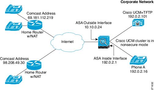
Example 2: Mixed-mode Cisco UCM cluster, Cisco UCM and TFTP Server on Publisher
Figure 48-3 shows an example of the configuration for a mixed-mode Cisco UCM cluster using the following topology.
Figure 48-3 Mixed-mode Cisco UCM cluster, Cisco UCM and TFTP Server on Publisher
Example 3: Mixed-mode Cisco UCM cluster, Cisco UCM and TFTP Server on Different Servers
Figure 48-4 shows an example of the configuration for a mixed-mode Cisco UCM cluster using the following topology where the TFTP server resides on a different server from the Cisco UCM.
In this sample, the static interface PAT for the TFTP server is configured to appear like the ASA’s outside interface IP address.
Figure 48-4 Mixed-mode Cisco UCM cluster, Cisco UCM and TFTP Server on Different Servers
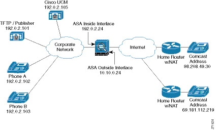
Example 4: Mixed-mode Cisco UCM cluster, Primary Cisco UCM, Secondary and TFTP Server on Different Servers
Figure 48-5 shows an example of the configuration for a mixed-mode Cisco UCM cluster using the following topology where the TFTP server resides on a different server from the primary and secondary Cisco UCMs.
In this sample, the static interface PAT for the TFTP server is configured to appear like the ASA’s outside interface IP address.
Figure 48-5 Mixed-mode Cisco UCM cluster, Primary Cisco UCM, Secondary Cisco UCM, and TFTP Server on Different Servers
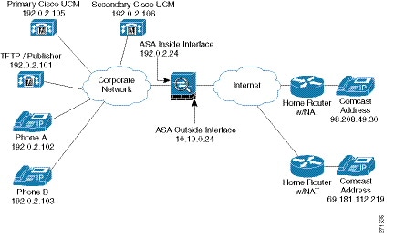
Example 5: LSC Provisioning in Mixed-mode Cisco UCM cluster; Cisco UCM and TFTP Server on Publisher
Figure 48-6 shows an example of the configuration for a mixed-mode Cisco UCM cluster where LSC provisioning is required using the following topology.
Note![]() Doing LSC provisioning for remote IP phones is not recommended because it requires that the IP phones first register and they have to register in nonsecure mode. Having the IP phones register in nonsecure mode requires the Administrator to open the nonsecure signaling port for SIP and SCCP on the ASA. If possible, LSC provisioning should be done inside the corporate network before giving the IP phones to the end-users.
Doing LSC provisioning for remote IP phones is not recommended because it requires that the IP phones first register and they have to register in nonsecure mode. Having the IP phones register in nonsecure mode requires the Administrator to open the nonsecure signaling port for SIP and SCCP on the ASA. If possible, LSC provisioning should be done inside the corporate network before giving the IP phones to the end-users.
In this sample, you create an access list to allow the IP phones to contact the TFTP server and to allow the IP phones to register in nonsecure mode by opening the nonsecure port for SIP and SCCP as well as the CAPF port for LSC provisioning.
Additionally, you create the CAPF trustpoint by copying and pasting the CAPF certificate from the Cisco UCM Certificate Management software.
Figure 48-6 LSC Provisioning in Mixed-mode Cisco UCM cluster; Cisco UCM and TFTP Server on Publisher
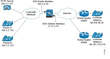
Example 6: VLAN Transversal
Figure 48-7 shows an example of the configuration to force Cisco IP Communicator (CIPC) softphones to operate in authenticated mode when CIPC softphones are deployed in a voice and data VLAN scenario. VLAN transversal is required between CIPC softphones on the data VLAN and hard phones on the voice VLAN.
In this sample, the Cisco UCM cluster mode is nonsecure.
In this sample, you create an access list to allow the IP phones to contact the TFTP server and to allow the IP phones to register in nonsecure mode by opening the nonsecure port for SIP and SCCP as well as the CAPF port for LSC provisioning.
In this sample, you configure NAT for the CIPC by using PAT so that each CIPC is mapped to an IP address space in the Voice VLAN.
Additionally, you create the CAPF trustpoint by copying and pasting the CAPF certificate from the Cisco UCM Certificate Management software.
Note![]() Cisco IP Communicator supports authenticated mode only and does not support encrypted mode; therefore, there is no encrypted voice traffic (SRTP) flowing from the CIPC softphones.
Cisco IP Communicator supports authenticated mode only and does not support encrypted mode; therefore, there is no encrypted voice traffic (SRTP) flowing from the CIPC softphones.
Figure 48-7 VLAN Transversal Between CIPC Softphones on the Data VLAN and Hard Phones on the Voice VLAN
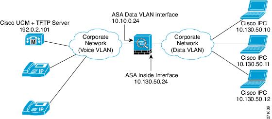
Feature History for the Phone Proxy
Table 48-7 lists the release history for this feature.
 Feedback