Cisco IOS XR System Monitoring Configuration Guide for the Cisco XR 12000 Series Router, Release 4.3.x
Bias-Free Language
The documentation set for this product strives to use bias-free language. For the purposes of this documentation set, bias-free is defined as language that does not imply discrimination based on age, disability, gender, racial identity, ethnic identity, sexual orientation, socioeconomic status, and intersectionality. Exceptions may be present in the documentation due to language that is hardcoded in the user interfaces of the product software, language used based on RFP documentation, or language that is used by a referenced third-party product. Learn more about how Cisco is using Inclusive Language.
- Updated:
- December 20, 2012
Chapter: Implementing IP Service Level Agreements
- Prerequisites for Implementing IP Service Level Agreements
- Restrictions for Implementing IP Service Level Agreements
- Information About Implementing IP Service Level Agreements
- About IP Service Level Agreements Technology
- Service Level Agreements
- Benefits of IP Service Level Agreements
- Measuring Network Performance with IP Service Level Agreements
- Operation Types for IP Service Level Agreements
- IP SLA Responder and IP SLA Control Protocol
- Response Time Computation for IP SLA
- IP SLA VRF Support
- IP SLA Operation Scheduling
- IP SLA—Proactive Threshold Monitoring
- MPLS LSP Monitoring
- LSP Path Discovery
- How to Implement IP Service Level Agreements
- Configuring IP Service Levels Using the UDP Jitter Operation
- Enabling the IP SLA Responder on the Destination Device
- Configuring and Scheduling a UDP Jitter Operation on the Source Device
- Prerequisites for Configuring a UDP Jitter Operation on the Source Device
- Configuring and Scheduling a Basic UDP Jitter Operation on the Source Device
- Configuring and Scheduling a UDP Jitter Operation with Additional Characteristics
- Configuring the IP SLA for a UDP Echo Operation
- Configuring an ICMP Echo Operation
- Configuring the ICMP Path-echo Operation
- Configuring the ICMP Path-jitter Operation
- Configuring IP SLA MPLS LSP Ping and Trace Operations
- Configuring IP SLA Reactions and Threshold Monitoring
- Configuring the MPLS LSP Monitoring Instance on a Source PE Router
- Configuring the Reaction Conditions for an MPLS LSP Monitoring Instance on a Source PE Router
- Scheduling an MPLS LSP Monitoring Instance on a Source PE Router
- LSP Path Discovery
- Configuring IP Service Levels Using the UDP Jitter Operation
- Configuration Examples for Implementing IP Service Level Agreements
- Additional References
Implementing IP
Service Level Agreements
IP Service Level Agreements (IP SLAs) is a portfolio of technology embedded in most devices that run Cisco IOS XR Software, which allows you to analyze IP service levels for IP applications and services, increase productivity, lower operational costs, and reduce the frequency of network outages.
Using IP SLA, service provider customers can measure and provide service level agreements. IP SLA can perform network assessments, verify quality of service (QoS), ease the deployment of new services, and assist administrators with network troubleshooting.
 Note | For a complete description of the IP SLA commands used in this chapter, refer to the IP Service Level Agreement Commands on the Cisco IOS XR Software module of Cisco IOS XR System Management Command Reference for the Cisco XR 12000 Series Router. |
Feature History for Implementing IP Service Level Agreements
|
Release |
Modification |
|---|---|
|
Release 3.3.0 |
This feature was introduced. |
|
Release 3.4.0 |
Support was added for MPLS LSP ping and MPLS LSP trace operations. Support was added for the use of nondefault VPN routing and forwarding (VRF) tables. |
|
Release 3.5.0 |
Support was added for MPLS LSP monitoring. Support was added for LSP pseudowire target configurations. |
|
Release 3.6.0 |
Support was added for LSP Path Discovery. |
|
Release 3.7.0 |
The LSP Path Discovery configuration task was expanded. |
- Prerequisites for Implementing IP Service Level Agreements
- Restrictions for Implementing IP Service Level Agreements
- Information About Implementing IP Service Level Agreements
- How to Implement IP Service Level Agreements
- Configuration Examples for Implementing IP Service Level Agreements
- Additional References
Prerequisites for Implementing IP Service Level Agreements
Knowledge of general networking protocols and your specific network design is assumed. Familiarity with network management applications is helpful. We do not recommend scheduling all the operations at the same time as this could negatively affect your performance.
You must be in a user group associated with a task group that includes the proper task IDs. The command reference guides include the task IDs required for each command. If you suspect user group assignment is preventing you from using a command, contact your AAA administrator for assistance.
Restrictions for Implementing IP Service Level Agreements
-
The maximum number of IP SLA configurable operations that is supported by Cisco IOS XR Software is 2000.
-
The current validated scale numbers for scheduling operations are as follows:
-
The number of UDP echo operations is 1000 operations with default frequency.
-
The number of UDP jitter operations is 1000 operations with default frequency.
-
The number of ICMP echo operations is 1000 operations with default frequency.
-
The number of ICMP echo-path operations is 400 operations with default frequency.
-
The ICMP jitter operations that can be configured with default frequency without packet loss is 75.
-
The MPLS LSP ping operations that can be configured with default frequency without packet loss is 100.
-
The MPLS LSP trace operations that can be configured with default frequency without packet loss is 100.
-
-
We do not recommend scheduling all the operations at the same start time as this may affect the performance. At the same start time, not more than 10 operations per second should be scheduled. We recommend using the start after configuration.
Note
Setting the frequency to less than 60 seconds will increase the number of packets sent. But this could negatively impact the performance of IP SLA operation when scheduled operations have same start time. -
IP SLA is not HA capable.
-
Consider the following guidelines before configuring the frequency, timeout, and threshold commands.
Information About Implementing IP Service Level Agreements
About IP Service Level Agreements Technology
IP SLA uses active traffic monitoring, which generates traffic in a continuous, reliable, and predictable manner to measure network performance. IP SLA sends data across the network to measure performance between multiple network locations or across multiple network paths. It simulates network data and IP services, and collects network performance information in real time. This information is collected:
-
Response times
-
One-way latency, jitter (interpacket delay variance)
-
Packet loss
-
Network resource availability
IP SLA originated from the technology previously known as Service Assurance Agent (SAA). IP SLA performs active monitoring by generating and analyzing traffic to measure performance, either between the router or from a router to a remote IP device such as a network application server. Measurement statistics, which are provided by the various IP SLA operations, are used for troubleshooting, problem analysis, and designing network topologies.
Depending on the specific IP SLA operation, statistics of delay, packet loss, jitter, packet sequence, connectivity, and path are monitored by and stored in the router and provided through command-line interface (CLI), Extensive Markup Language (XML), and SNMP MIBs. IP SLA uses the Cisco RTTMON MIB to interact between external Network Management System (NMS) applications and the IP SLA operations that are running on Cisco devices. For a complete description of the object variables that are referenced by IP SLA, see the text of the CISCO-RTTMON-MIB.my file that is available from the Cisco MIB Locator.
Service Level Agreements
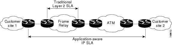
Internet commerce has grown significantly in the past few years as the technology has advanced to provide faster, more reliable access to the Internet. Many companies need online access and conduct most of their business on line and any loss of service can affect the profitability of the company. Internet service providers (ISPs) and even internal IT departments now offer a defined level of service—a service level agreement—to provide their customers with a degree of predictability.
Network administrators are required to support service level agreements that support application solutions. Figure 1 shows how IP SLA has taken the traditional concept of Layer 2 service level agreements and applied a broader scope to support end-to-end performance measurement, including support of applications.
|
Type of Improvement |
Description |
|---|---|
|
End-to-end measurements |
The ability to measure performance from one end of the network to the other allows a broader reach and more accurate representation of the end-user experience. |
|
Sophistication |
Statistics, such as delay, jitter, packet sequence, Layer 3 connectivity, and path and download time, that are divided into bidirectional and round-trip numbers provide more data than just the bandwidth of a Layer 2 link. |
|
Accuracy |
Applications that are sensitive to slight changes in network performance require the precision of the submillisecond measurement of IP SLA. |
|
Ease of deployment |
Leveraging the existing Cisco devices in a large network makes IP SLA easier to implement than the physical operations that are often required with traditional service level agreements. |
|
Application-aware monitoring |
IP SLA can simulate and measure performance statistics generated by applications running over Layer 3 through Layer 7. Traditional service level agreements can measure only Layer 2 performance. |
|
Pervasiveness |
IP SLA support exists in Cisco networking devices ranging from low-end to high-end routers and switches. This wide range of deployment gives IP SLA more flexibility over traditional service level agreements. |
Benefits of IP Service Level Agreements
This table lists the benefits of implementing IP SLA.
|
Benefit |
Description |
|---|---|
|
IP SLA monitoring |
Provides service level agreement monitoring, measurement, and verification. |
|
Network performance monitoring |
Measure the jitter, latency, or packet loss in the network. In addition, IP SLA provides continuous, reliable, and predictable measurements along with proactive notification. |
|
IP service network health assessment |
Verifies that the existing QoS is sufficient for the new IP services. |
|
Troubleshooting of network operation |
Provides consistent, reliable measurement that immediately identifies problems and saves troubleshooting time. |
Measuring Network Performance with IP Service Level Agreements
IP SLA uses generated traffic to measure network performance between two networking devices, such as routers. Figure 1 shows how IP SLA starts when the IP SLA device sends a generated packet to the destination device. After the destination device receives the packet and if the operation uses an IP SLA component at the receiving end (for example, IP SLA Responder), the reply packet includes information about the delay at the target device. The source device uses this information to improve the accuracy of the measurements. An IP SLA operation is a network measurement to a destination in the network from the source device using a specific protocol, such as User Datagram Protocol (UDP) for the operation.
Operations are divided into two classes, which depend on whether they rely on the IP SLA Responder component to be running at the target device or not. The former is used only with Cisco devices; whereas, the latter is used with any device that has IP connectivity. Operations that are based on Internet Control Message Protocol (ICMP) are examples of the second class; whereas, UDP-based operations are examples of the first.
In responder-based operations, the IP SLA Responder is enabled in the destination device and provides information such as the processing delays of IP SLA packets. The responder-based operation has improved accuracy over the ICMP operation discussed above, and offers the capability of unidirectional measurements. In replies to the IP SLA source device, the responder includes information about processing delays. The IP SLA source device removes the delays in its final performance calculation. Use of the responder is optional for the UDP echo operation, but it is required for the UDP jitter operation. If no IP SLA Responder is used, the target device should support the UDP echo operation.
In ICMP operations, the source IP SLA device sends several ICMP packets to the destination. The destination device, which is any IP device, echoes with replies. The source IP SLA device uses the sent and received time stamps to calculate the response time. The ICMP echo operation resembles the traditional extended ping utility, and it measures only the response time between the source device and the destination device. ICMP path-echo and path-jitter operations use the traceroute mechanism to identify the whole path. Subsequent ICMP packets are sent to each path node, and the measurements are correlated to provide hop-by-hop round-trip delay and jitter information.
To implement IP SLA network performance measurement, perform these tasks:
-
Enable the IP SLA Responder, if appropriate.
-
Configure the required IP SLA operation type.
-
Configure any options available for the specified IP SLA operation type.
-
Configure reaction conditions, if required.
-
Schedule the operation to run. Then, let the operation run for a period of time to gather statistics.
-
Display and interpret the results of the operation using Cisco IOS XR Software CLI, XML, or an NMS system with SNMP.
Operation Types for IP Service Level Agreements
IP SLA configures various types of operations to measure response times, jitter, throughput, and packet loss. Also, each operation maps to multiple applications.
This table lists the various types of operations.
|
Operation |
Description |
|---|---|
|
UDP echo |
Measures round-trip delay and helps in accurate measurement of response time of UDP traffic. |
|
UDP jitter |
Measures round-trip delay, one-way delay, one-way jitter, two-way jitter, and one-way packet loss. |
|
ICMP echo |
Measures round-trip delay for the full path. |
|
ICMP path-echo |
Calculates the hop-by-hop response time between the router and any IP device on the network. The path is discovered using the traceroute algorithm and then by measuring the response time between the source router and each intermediate hop in the path. If there are multiple equal-cost routes between source and destination devices, the ICMP path-echo operation can select one of the paths by using the Loose Source Routing (LSR) option, which is configurable. |
|
ICMP path-jitter |
Measures hop-by-hop jitter, packet loss, and delay measurement statistics in an IP network. |
|
MPLS LSP ping |
Tests the connectivity of a label switched paths (LSP) and measures round-trip delay of the LSP in an MPLS network. The following Forwarding Equivalence Classes (FECs) are supported: An echo request is sent along the same data path as other packets belonging to the FEC. When the echo request packet reaches the end of the path, it is sent to to the control plane of the egress label switching router (LSR). The LSR verifies that it is indeed an egress for the FEC and sends an echo reply packet that contains information about the FEC whose MPLS path is being verified. Only a default VRF table is supported. |
|
MPLS LSP trace |
Traces the hop-by-hop route of an LSP path and measures the hop-by-hop round-trip delay for IPv4 LDP prefixes and TE tunnel FECs in an MPLS network. An echo request packet is sent data to the control plane of each transit LSR, which checks if it is a transit LSR for this path. Each transit LSR also returns information related to the label bound to the FEC that is being tested. Only a default VRF table is supported. |
IP SLA Responder and IP SLA Control Protocol
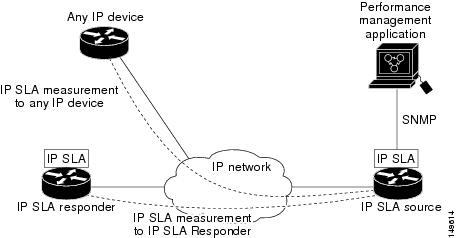
The IP SLA Responder is a component embedded in the destination Cisco routing device that allows the system to anticipate and respond to IP SLA request packets. The IP SLA Responder provides enhanced accuracy for measurements. Additional statistics are also provided, which are not otherwise available through standard ICMP-based measurements. The patented IP SLA Control Protocol is used by the IP SLA Responder, providing a mechanism through which the responder is notified on which port it should listen and respond. Only a Cisco IOS XR Software device or other Cisco platforms can be a source for a destination IP SLA Responder.
Figure 1 shows where the IP SLA Responder fits relative to the IP network. The IP SLA Responder listens on a specific port for control protocol messages sent by an IP SLA operation. Upon receipt of the control message, the responder enables the UDP port specified in the control message for the specified duration. During this time, the responder accepts the requests and responds to them. The responder disables the port after it responds to the IP SLA packet or packets, or when the specified time expires. For added security, MD5 authentication for control messages is available.
Note | The IP SLA responder needs at least one second to open a socket and program Local Packet Transport Services (LPTS). Therefore, configure the IP SLA timeout to at least 2000 milli seconds. |
The IP SLA Responder must be used with the UDP jitter operation, but it is optional for UDP echo operation. If services that are already provided by the target router are chosen, the IP SLA Responder need not be enabled. For devices that are not Cisco devices, the IP SLA Responder cannot be configured, and the IP SLA can send operational packets only to services native to those devices.
Response Time Computation for IP SLA
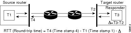
T3 is the time the reply packet is sent at the IP SLA Responder node, and T1 is the time the request is sent at the source node. Because of other high-priority processes, routers can take tens of milliseconds to process incoming packets. The delay affects the response times, because the reply to test packets might be sitting in a queue while waiting to be processed. In this situation, the response times would not accurately represent true network delays. IP SLA minimizes these processing delays on the source router and on the target router (if IP SLA Responder is being used) to determine true round-trip times. Some IP SLA probe packets contain delay information that are used in the final computation to make measurements more accurate.
When enabled, the IP SLA Responder allows the target device to take two time stamps, both when the packet arrives on the interface and again just as it is leaving, and accounts for it when calculating the statistics. This time stamping is made with a granularity of submilliseconds. At times of high network activity, an ICMP ping test often shows a long and inaccurate response time, while an IP SLA-based responder shows an accurate response time.
Figure 1 shows how the responder works. Four time stamps are taken to make the calculation for round-trip time. At the target router, with the responder functionality enabled, time stamp 2 (TS2) is subtracted from time stamp 3 (TS3) to produce the time spent processing the test packet as represented by delta. This delta value is then subtracted from the overall round-trip time. Notice that the same principle is applied by IP SLA on the source router on which the incoming time stamp 4 (TS4) is taken in a high-priority path to allow for greater accuracy.
IP SLA VRF Support
Service providers need to monitor and measure network performance from both the perspective of the core network and a customer’s network. To do so, it is necessary to use nondefault VPN routing and forwarding (VRF) tables for IP SLA operations in addition to the default VRF table. Table 1 describes the different IP SLA operations, including information about whether or not an operation supports the use of nondefault VRF tables.
IP SLA Operation Scheduling
Note | Multiple SLA probes with the same configuration (source and port number) must not be scheduled to run simultaneously. |
IP SLA—Proactive Threshold Monitoring
This section describes the proactive monitoring capabilities for IP SLA that use thresholds and reaction triggering. IP SLA allows you to monitor, analyze, and verify IP service levels for IP applications and services to increase productivity, lower operational costs, and reduce occurrences of network congestion or outages. IP SLA uses active traffic monitoring to measure network performance.
To perform the tasks that are required to configure proactive threshold monitoring using IP SLA, you must understand these concepts:
IP SLA Reaction Configuration
IP SLA is configured to react to certain measured network conditions. For example, if IP SLA measures too much jitter on a connection, IP SLA can generate a notification to a network management application or trigger another IP SLA operation to gather more data.
IP SLA reaction configuration is performed by using the ipsla reaction operation command.
IP SLA Threshold Monitoring and Notifications
IP SLA supports threshold monitoring for performance parameters, such as jitter-average, bidirectional round-trip time, and connectivity. For packet loss and jitter, notifications can be generated for violations in either direction (for example, the source to the destination and the destination to the source) or for round-trip values.
MPLS LSP Monitoring
The IP Service Level Agreements (SLAs) label switched path (LSP) monitor feature provides the capability to proactively monitor Layer 3 Multiprotocol Label Switching (MPLS) Virtual Private Networks (VPNs). This feature is useful for determining network availability or testing network connectivity between provider edge (PE) routers in an MPLS VPN. When configured, MPLS LSP monitor automatically creates and deletes IP SLA LSP ping or LSP traceroute operations based on network topology.
The MPLS LSP monitor feature also allows you to perform multi-operation scheduling of IP SLA operations and supports proactive threshold violation monitoring through SNMP trap notifications and syslog messages.
To use the MPLS LSP monitor feature, you must understand these concepts:
- How MPLS LSP Monitoring Works
- BGP Next-hop Neighbor Discovery
- IP SLA LSP Ping and LSP Traceroute Operations
- Proactive Threshold Monitoring for MPLS LSP Monitoring
- Multi-operation Scheduling for the LSP Health Monitor
How MPLS LSP Monitoring Works
The MPLS LSP monitor feature provides the capability to proactively monitor Layer 3 MPLS VPNs. The general process for how the MPLS LSP monitor works is as follows:
-
The user configures an MPLS LSP monitor instance.
Configuring an MPLS LSP monitor instance is similar to configuring a standard IP SLA operation. To illustrate, all operation parameters for an MPLS LSP monitor instance are configured after an identification number for the operation is specified. However, unlike standard IP SLA operations, these configured parameters are then used as the base configuration for the individual IP SLA LSP ping and LSP traceroute operations that will be created by the MPLS LSP monitor instance.
When the first MPLS LSP monitor instance is configured and scheduled to begin, BGP next-hop neighbor discovery is enabled. See the BGP Next-hop Neighbor Discovery.
-
The user configures proactive threshold violation monitoring for the MPLS LSP monitor instance.
-
The user configures multioperation scheduling parameters for the MPLS LSP monitor instance.
-
Depending on the configuration options chosen, the MPLS LSP monitor instance automatically creates individual IP SLA LSP ping or LSP traceroute operations for each applicable BGP next-hop neighbor.
For any given MPLS LSP monitor operation, only one IP SLA LSP ping or LSP traceroute operation is configured per BGP next-hop neighbor. However, more than one MPLS LSP monitor instance can be running on a particular PE router at the same time. (For more details, see the note at the end of this section.)
-
Each IP SLA LSP ping or LSP traceroute operation measures network connectivity between the source PE router and the discovered destination PE router.
Note
More than one MPLS LSP monitor instance can be running on a particular PE router at the same time. For example, one MPLS LSP monitor instance can be configured to discover BGP next-hop neighbors belonging to the VRF named VPN1. On the same PE router, another MPLS LSP monitor instance can be configured to discover neighbors belonging to the VRF named VPN2. In this case, if a BGP next-hop neighbor belonged to both VPN1 and VPN2, then the PE router would create two IP SLA operations for this neighbor—one for VPN1 and one for VPN2.
Adding and Deleting IP SLA Operations from the MPLS LSP Monitor Database
The MPLS LSP monitor instance receives periodic notifications about BGP next-hop neighbors that have been added to or removed from a particular VPN. This information is stored in a queue maintained by the MPLS LSP monitor instance. Based on the information in the queue and user-specified time intervals, new IP SLA operations are automatically created for newly discovered PE routers and existing IP SLA operations are automatically deleted for any PE routers that are no longer valid.
BGP Next-hop Neighbor Discovery
BGP next-hop neighbor discovery is used to find the BGP next-hop neighbors in use by any VRF associated with the source provider edge (PE) router. In most cases, these neighbors are PE routers.
When BGP next-hop neighbor discovery is enabled, a database of BGP next-hop neighbors in use by any VRF associated with the source PE router is generated, based on information from the local VRF and global routing tables. As routing updates are received, new BGP next-hop neighbors are added immediately to the database. However, BGP next-hop neighbors that are no longer valid are removed from the database only periodically, as defined by the user.
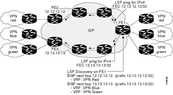
Figure 1 shows how BGP next-hop neighbor discovery works for a simple VPN scenario for an Internet service provider (ISP). In this example, there are three VPNs associated with router PE1: red, blue, and green. From the perspective of router PE1, these VPNs are reachable remotely through BGP next-hop neighbors PE2 (router ID: 12.12.12.12) and PE3 (router ID: 13.13.13.13). When the BGP next-hop neighbor discovery process is enabled on router PE1, a database is generated based on the local VRF and global routing tables. The database in this example contains two BGP next-hop router entries, PE2 12.12.12.12 and PE3 13.13.13.13. The routing entries are maintained per next-hop router to distinguish which next-hop routers belong within which particular VRF. For each next-hop router entry, the IPv4 Forward Equivalence Class (FEC) of the BGP next-hop router in the global routing table is provided so that it can be used by the MPLS LSP ping operation.
IP SLA LSP Ping and LSP Traceroute Operations
This feature introduces support for the IP SLA LSP ping and IP SLA LSP traceroute operations. These operations are useful for troubleshooting network connectivity issues and determining network availability in an MPLS VPN. When using MPLS LSP monitoring, IP SLA LSP ping and LSP traceroute operations are automatically created to measure network connectivity between the source PE router and the discovered destination PE routers. Individual IP SLA LSP ping and LSP traceroute operations can also be manually configured. Manual configuration of these operations can be useful for troubleshooting a connectivity issue.
For more information about how to configure IP SLA LSP ping or LSP traceroute operations using MPLS LSP monitoring, see the Configuring an MPLS LSP Monitoring Ping Instance and the Configuring an MPLS LSP Monitoring Trace Instance.
The IP SLA LSP ping and IP SLA LSP traceroute operations are based on the same infrastructure used by the MPLS LSP Ping and MPLS LSP Traceroute features, respectively, for sending and receiving echo reply and request packets to test LSPs.
Proactive Threshold Monitoring for MPLS LSP Monitoring
Proactive threshold monitoring support for the MPLS LSP Monitor feature provides the capability for triggering SNMP trap notifications and syslog messages when user-defined reaction conditions (such as a connection loss or timeout) are met. Configuring threshold monitoring for an MPLS LSP monitor instance is similar to configuring threshold monitoring for a standard IP SLAs operation.
Multi-operation Scheduling for the LSP Health Monitor
Multioperation scheduling support for the MPLS LSP Monitor feature provides the capability to easily schedule the automatically created IP SLA operations (for a given MPLS LSP monitor instance) to begin at intervals equally distributed over a specified duration of time (schedule period) and to restart at a specified frequency. Multioperation scheduling is particularly useful in cases where MPLS LSP monitoring is enabled on a source PE router that has a large number of PE neighbors and, therefore, a large number of IP SLAs operations running at the same time.
Note | Newly created IP SLA operations (for newly discovered BGP next-hop neighbors) are added to the same schedule period as the operations that are currently running. To prevent too many operations from starting at the same time, the multioperation scheduling feature schedules the operations to begin at random intervals uniformly distributed over the schedule period. |
LSP Path Discovery
LSP Path Discovery (LPD) is an enhancement to MPLS LSP monitor (MPLSLM) that allows operations that are part of an MPLSLM instance to initiate the path discovery process and to process the results. This feature relies on the tree trace capabilities provided by the MPLS OAM infrastructure through the LSPV server.
When multiple paths with equal cost exist between two PE routers, also know as equal cost multipath (ECMP), routers between these PE routers perform load balancing on the traffic, based on characteristics of the traffic being forwarded (for example. the destination address in the packet). In network topologies such as this, monitoring only one (or some) of the available paths among PE routers does not provide any guarantee that traffic will be forwarded correctly.
LPD is configured using the path discover command.
Note | LPD functionality may create considerable CPU demands when large numbers of path discovery requests are received by the LSPV server at one time. |
How to Implement IP Service Level Agreements
Configuring IP Service Levels Using the UDP Jitter Operation
The IP SLA UDP jitter monitoring operation is designed to diagnose network suitability for real-time traffic applications such as VoIP, Video over IP, or real-time conferencing.
Jitter means interpacket delay variance. When multiple packets are sent consecutively from source to destination—for example, 10 ms apart—and if the network is behaving ideally, the destination can receive them 10 ms apart. But if there are delays in the network (for example, queuing, arriving through alternate routes, and so on), the arrival delay between packets can be greater than or less than 10 ms. Using this example, a positive jitter value indicates that the packets arrived more than 10 ms apart. If the packets arrive 12 ms apart, positive jitter is 2 ms; if the packets arrive 8 ms apart, negative jitter is 2 ms. For delay-sensitive networks like VoIP, positive jitter values are undesirable, and a jitter value of 0 is ideal.
However, the IP SLA UDP jitter operation does more than just monitor jitter. The packets that IP SLA generates carry sending sequence and receiving sequence information for the packets, and sending and receiving time stamps from the source and the operational target. Based on these, UDP jitter operations are capable of measuring the following functions:
-
Per-direction jitter (source to destination and destination to source)
-
Per-direction packet-loss
-
Per-direction delay (one-way delay)
-
Round-trip delay (average round-trip time)
As the paths for the sending and receiving of data may be different (asymmetric), the per-direction data allows you to more readily identify where congestion or other problems are occurring in the network.
The UDP jitter operation functions by generating synthetic (simulated) UDP traffic. By default, ten packet-frames (N), each with a payload size of 32 bytes (S) are generated every 20 ms (T), and the operation is repeated every 60 seconds (F). Each of these parameters is user-configurable, so as to best simulate the IP service you are providing, or want to provide.
This section contains these procedures:
- Enabling the IP SLA Responder on the Destination Device
- Configuring and Scheduling a UDP Jitter Operation on the Source Device
- Prerequisites for Configuring a UDP Jitter Operation on the Source Device
- Configuring and Scheduling a Basic UDP Jitter Operation on the Source Device
- Configuring and Scheduling a UDP Jitter Operation with Additional Characteristics
Enabling the IP SLA Responder on the Destination Device
The IP SLA Responder must be enabled on the target device, which is the operational target.
By configuring the ipsla responder command, you make the IP SLA Responder open a UDP port 1967 and wait for a control request (not for probes). You can open or close a port dynamically through the IP SLA control protocol (through UDP port 1967). In addition, you can configure permanent ports.
Permanent ports are open until the configuration is removed. Agents can send IP SLA probe packets to the permanent port directly without a control request packet because the port can be opened by the configuration.
If you do not use permanent ports, you have to configure only the ipsla responder command.
To use a dynamic port, use the ipsla responder command, as shown in this example:
configure
ipsla responder
The dynamic port is opened through the IP SLA control protocol on the responder side when you start an operation on the agent side.
The example is configured as a permanent port on the responder. UDP echo and UDP jitter can use a dynamic port or a permanent port. If you use a permanent port for UDP jitter, there is no check performed for duplicated or out-of-sequence packets. This is because there is no control packet to indicate the start or end of the probe sequence. Therefore, the verification for sequence numbers are skipped when using permanent ports.
1.
configure
2.
ipsla
responder
3.
type
udp
ipv4
address
ip-address
port
port
4.
commit
DETAILED STEPS
After enabling the IP SLA Responder, see the Configuring and Scheduling a UDP Jitter Operation on the Source Device section.
Configuring and Scheduling a UDP Jitter Operation on the Source Device
The IP SLA operations function by generating synthetic (simulated) network traffic. A single IP SLA operation (for example, IP SLA operation 10) repeats at a given frequency for the lifetime of the operation.
A single UDP jitter operation consists of N UDP packets, each of size S, sent T milliseconds apart, from a source router to a target router, at a given frequency of F. By default, ten packets (N), each with a payload size of 32 bytes (S), are generated every 20 ms (T), and the operation is repeated every 60 seconds (F). Each of these parameters is user configurable, as shown in Table 1.
|
UDP Jitter Operation Parameter |
Default |
Configured Using |
|---|---|---|
|
Number of packets (N) |
10 packets |
|
|
Payload size per packet (S) |
32 bytes |
|
|
Time between packets, in milliseconds (T) |
20 ms |
|
|
Elapsed time before the operation repeats, in seconds (F) |
60 seconds |
Prerequisites for Configuring a UDP Jitter Operation on the Source Device
Use of the UDP jitter operation requires that the IP SLA Responder be enabled on the target Cisco device. To enable the IP SLA Responder, perform the task in the Enabling the IP SLA Responder on the Destination Device section.
Configuring and Scheduling a Basic UDP Jitter Operation on the Source Device
You can configure and schedule a UDP jitter operation.
1.
configure
2.
ipsla operation
operation-number
3.
type
udp
jitter
4.
destination address
ipv4address
5.
destination port
port
6.
packet
count
count
7.
packet interval
interval
8.
frequency
seconds
9.
exit
10.
ipsla schedule operation
op-num
11. life { forever | seconds}
12.
ageout
seconds
13.
recurring
14.
start-time [hh:mm:ss {day |
month
day} |
now
|
pending |
after
hh:mm:ss]
15.
commit
DETAILED STEPS
Configuring and Scheduling a UDP Jitter Operation with Additional Characteristics
You can configure and schedule a UDP jitter operation.
1.
configure
2.
ipsla operation
operation-number
3.
type
udp
jitter
4.
vrf
vrf-name
5.
destination address
ipv4address
6.
destination port
port
7.
frequency
seconds
8.
statistics [hourly |
interval
seconds]
9.
buckets
hours
10.
distribution count
slot
11.
distribution interval
interval
12.
exit
13.
datasize
request
size
14.
timeout
milliseconds
15.
tos
number
16.
exit
17.
ipsla schedule operation
op-num
18.
life {forever |
seconds}
19.
ageout
seconds
20.
recurring
21.
start-time [hh:mm:ss {day |
month
day} |
now
|
pending |
after
hh:mm:ss ]
22.
commit
23.
show ipsla statistics
[operation-number ]
24.
show ipsla statistics
aggregated [operation-number ]
DETAILED STEPS
Configuring the IP SLA for a UDP Echo Operation
To measure UDP performance on a network, use the IP SLA UDP echo operation. A UDP echo operation measures round-trip delay times and tests connectivity to Cisco devices and devices that are not Cisco devices. The results of a UDP echo operation can be useful in troubleshooting issues with business-critical applications.
Note | The UDP echo operation requires a Cisco device that is running the IP SLA Responder or a non-Cisco device that is running the UDP echo service. |
Depending on whether you want to configure a basic UDP echo operation or to configure a UDP echo operation with optional parameters, perform one of the following tasks:
- Prerequisites for Configuring a UDP Echo Operation on the Source Device
- Configuring and Scheduling a UDP Echo Operation on the Source Device
- Configuring and Scheduling a UDP Echo Operation with Optional Parameters on the Source Device
Prerequisites for Configuring a UDP Echo Operation on the Source Device
If you are using the IP SLA Responder, ensure that you have completed the Enabling the IP SLA Responder on the Destination Device section.
Configuring and Scheduling a UDP Echo Operation on the Source Device
You can enable a UDP echo operation without any optional parameters.
1.
configure
2.
ipsla operation
operation-number
3.
type
udp
echo
4.
destination address
ipv4address
5.
destination port
port
6.
frequency
seconds
7.
exit
8.
ipsla schedule operation
op-num
9.
life [forever |
seconds]
10.
ageout
seconds
11.
recurring
12.
start-time [hh:mm:ss {day |
month
day} |
now
|
pending |
after
hh:mm:ss ]
13.
commit
14.
show ipsla statistics
[operation-number]
15.
show ipsla statistics
aggregated [operation-number]
DETAILED STEPS
Configuring and Scheduling a UDP Echo Operation with Optional Parameters on the Source Device
You can enable a UDP echo operation on the source device and configure some optional IP SLA parameters. The source device is the location at which the measurement statistics are stored.
1.
configure
2.
ipsla operation
operation-number
3.
type
udp
echo
4.
vrf
vrf-name
5.
destination address
ipv4address
6.
destination port
port
7.
frequency
seconds
8.
datasize
request
size
9.
tos
number
10.
timeout
milliseconds
11.
tag
text
12.
exit
13.
ipsla schedule operation
op-num
14.
life {forever |
seconds}
15.
ageout
seconds
16.
recurring
17.
start-time [hh:mm:ss {day |
month
day} |
now
|
pending |
after
hh:mm:ss]
18.
commit
19.
show ipsla statistics
enhanced aggregated [operation-number]
interval
seconds
20.
show ipsla statistics
[operation-number]
DETAILED STEPS
Configuring an ICMP Echo Operation
To monitor IP connections on a device, use the IP SLA ICMP echo operation. An ICMP echo operation measures end-to-end response times between a Cisco router and devices using IP. ICMP echo is used to troubleshoot network connectivity issues.
Note | The ICMP echo operation does not require the IP SLA Responder to be enabled. |
Depending on whether you want to configure and schedule a basic ICMP echo operation or configure and schedule an ICMP echo operation with optional parameters, perform one of the following procedures:
- Configuring and Scheduling a Basic ICMP Echo Operation on the Source Device
- Configuring and Scheduling an ICMP Echo Operation with Optional Parameters on the Source Device
Configuring and Scheduling a Basic ICMP Echo Operation on the Source Device
You can enable and schedule an ICMP echo operation without any optional parameters.
1.
configure
2.
ipsla operation
operation-number
3.
type
icmp
echo
4.
destination address
ipv4address
5.
frequency
seconds
6.
exit
7.
ipsla schedule operation
op-num
8.
life {forever |
seconds}
9.
ageout
seconds
10.
recurring
11.
start-time [hh:mm:ss {day |
month
day} |
now
|
pending |
after
hh:mm:ss]
12.
commit
13.
show ipsla statistics
[operation-number]
DETAILED STEPS
| Command or Action | Purpose | |
|---|---|---|
| Step 1 |
configure
| |
| Step 2 | ipsla operation
operation-number
Example:
RP/0/0/CPU0:router(config)# ipsla operation 432
|
Specifies the operation number. The range is from 1 to 2048. |
| Step 3 | type
icmp
echo
Example:
RP/0/0/CPU0:router(config-ipsla-op)# type icmp echo
|
Defines an ICMP echo operation type. |
| Step 4 | destination address
ipv4address
Example:
RP/0/0/CPU0:router(config-ipsla-icmp-echo)# destination address 12.25.26.10
|
Specifies the IP address of the destination for the proper operation type. |
| Step 5 | frequency
seconds
Example:
RP/0/0/CPU0:router(config-ipsla-icmp-echo) frequency 300
|
(Optional) Sets the rate at which a specified IP SLA operation is sent into the network. |
| Step 6 | exit
Example: RP/0/0/CPU0:router(config-ipsla-icmp-echo)# exit RP/0/0/CPU0:router(config-ipsla-op)# exit RP/0/0/CPU0:router(config-ipsla)# exit RP/0/0/CPU0:router(config)# |
Exits IP SLA operation configuration mode and IP SLA configuration mode. Returns to global configuration mode. |
| Step 7 | ipsla schedule operation
op-num
Example: RP/0/0/CPU0:router(config)# ipsla schedule operation 432 RP/0/0/CPU0:router(config-ipsla-sched)# |
Schedules the start time of the operation. You can configure a basic schedule. |
| Step 8 | life {forever |
seconds}
Example:
RP/0/0/CPU0:router(config-ipsla-sched)# life 30
|
The forever keyword schedules the operation to run indefinitely. The seconds argument schedules the lifetime of the operation, in seconds. The default lifetime of an operation is 3600 seconds (one hour). |
| Step 9 | ageout
seconds
Example:
RP/0/0/CPU0:router(config-ipsla-sched)# ageout 3600
|
(Optional) Specifies the number of seconds to keep the operation in memory when it is not actively collecting information. The default value of 0 seconds means that the operation never times out. |
| Step 10 | recurring
Example:
RP/0/0/CPU0:router(config-ipsla-sched)# recurring
|
(Optional) Specifies that the operation starts automatically at the specified time and for the specified duration every day. |
| Step 11 | start-time [hh:mm:ss {day |
month
day} |
now
|
pending |
after
hh:mm:ss]
Example:
RP/0/0/CPU0:router(config-ipsla-sched)# start-time 01:00:00
|
Specifies a time for the operation to start. The following keywords are described:
|
| Step 12 |
commit
| |
| Step 13 | show ipsla statistics
[operation-number]
Example:
RP/0/0/CPU0:router # show ipsla statistics 432
|
Displays the current statistics. |
Configuring and Scheduling an ICMP Echo Operation with Optional Parameters on the Source Device
You can enable an ICMP echo operation on the source device and configure some optional IP SLA parameters.
1.
configure
2.
ipsla operation
operation-number
3.
type
icmp
echo
4.
vrf
vrf-name
5.
destination address
ipv4address
6.
frequency
seconds
7.
datasize
request
size
8.
tos
number
9.
timeout
milliseconds
10.
tag
text
11.
exit
12.
ipsla schedule operation
op-num
13.
life {forever |
seconds}
14.
ageout
seconds
15.
recurring
16.
start-time [hh:mm:ss {day |
month
day} |
now
|
pending |
after
hh:mm:ss]
17.
commit
18.
show ipsla statistics
[operation-number]
DETAILED STEPS
| Command or Action | Purpose | |||
|---|---|---|---|---|
| Step 1 |
configure
| |||
| Step 2 | ipsla operation
operation-number
Example:
RP/0/0/CPU0:router(config)# ipsla operation 432
|
Specifies the operation number. The range is from 1 to 2048. | ||
| Step 3 | type
icmp
echo
Example:
RP/0/0/CPU0:router(config-ipsla-op)# type icmp echo
|
Defines an ICMP echo operation type. | ||
| Step 4 | vrf
vrf-name
Example:
RP/0/0/CPU0:router(config-ipsla-icmp-echo)# vrf VPN-A
|
(Optional) Enables the monitoring of a VPN (using a nondefault routing table) in an ICMP echo operation. Maximum length is 32 alphanumeric characters. | ||
| Step 5 | destination address
ipv4address
Example:
RP/0/0/CPU0:router(config-ipsla-icmp-echo)# destination address 12.25.26.10
|
Specifies the IP address of the destination for the proper operation type. | ||
| Step 6 | frequency
seconds
Example:
RP/0/0/CPU0:router(config-ipsla-icmp-echo)# frequency 300
|
(Optional) Sets the rate at which a specified IP SLA operation is sent into the network. | ||
| Step 7 | datasize
request
size
Example:
RP/0/0/CPU0:router(config-ipsla-icmp-echo)# datasize request 512
|
(Optional) Sets the protocol data size in the payload of the request packet for the specified IP SLA operation. | ||
| Step 8 | tos
number
Example:
RP/0/0/CPU0:router(config-ipsla-icmp-echo)# tos 1
|
Defines a type of service (ToS) byte in the IP header of IP SLA operations.
| ||
| Step 9 | timeout
milliseconds
Example:
RP/0/0/CPU0:router(config-ipsla-icmp-echo)# timeout 10000
|
Sets the time that the IP SLA operation waits for a response from its request packet. | ||
| Step 10 | tag
text
Example:
RP/0/0/CPU0:router(config-ipsla-icmp-echo)# tag ipsla
|
(Optional) Creates a user-specified identifier for an IP SLA operation. | ||
| Step 11 |
exit
Example: RP/0/0/CPU0:router(config-ipsla-icmp-echo)# exit RP/0/0/CPU0:router(config-ipsla-op)# exit RP/0/0/CPU0:router(config-ipsla)# exit RP/0/0/CPU0:router(config)# |
Exits IP SLA operation configuration mode and IP SLA configuration mode. Returns to global configuration mode. | ||
| Step 12 | ipsla schedule operation
op-num
Example: RP/0/0/CPU0:router(config)# ipsla schedule operation 432 RP/0/0/CPU0:router(config-ipsla-sched)# |
Schedules the start time of the operation. You can configure a basic schedule. | ||
| Step 13 | life {forever |
seconds}
Example:
RP/0/0/CPU0:router(config-ipsla-sched)# life 30
|
The forever keyword schedules the operation to run indefinitely. The seconds argument schedules the lifetime of the operation, in seconds. The default lifetime of an operation is 3600 seconds (one hour). | ||
| Step 14 | ageout
seconds
Example:
RP/0/0/CPU0:router(config-ipsla-sched)# ageout 3600
|
(Optional) Specifies the number of seconds to keep the operation in memory when it is not actively collecting information. The default value of 0 seconds means that the operation never times out. | ||
| Step 15 | recurring
Example:
RP/0/0/CPU0:router(config-ipsla-sched)# recurring
|
(Optional) Specifies that the operation starts automatically at the specified time and for the specified duration every day. | ||
| Step 16 | start-time [hh:mm:ss {day |
month
day} |
now
|
pending |
after
hh:mm:ss]
Example:
RP/0/0/CPU0:router(config-ipsla-sched)# start-time 01:00:00
|
Specifies a time for the operation to start. The following keywords are described:
| ||
| Step 17 |
commit
| |||
| Step 18 | show ipsla statistics
[operation-number]
Example:
RP/0/0/CPU0:router # show ipsla statistics 432
|
Displays the current statistics. |
Configuring the ICMP Path-echo Operation
The IP SLA ICMP path-echo operation records statistics for each hop along the path that the IP SLA operation takes to reach its destination. The ICMP path-echo operation determines the hop-by-hop response time between a Cisco router and any IP device on the network by discovering the path using the traceroute facility.
The source IP SLA device uses traceroute to discover the path to the destination IP device. A ping is then used to measure the response time between the source IP SLA device and each subsequent hop in the path to the destination IP device.
Note | The ICMP path-echo operation does not require the IP SLA Responder to be enabled. |
Depending on whether you want to configure and schedule a basic ICMP path-echo operation or configure and schedule an ICMP path-echo operation with optional parameters, perform one of the following procedures:
- Configuring and Scheduling a Basic ICMP Path-echo Operation on the Source Device
- Configuring and Scheduling an ICMP Path-echo Operation with Optional Parameters on the Source Device
Configuring and Scheduling a Basic ICMP Path-echo Operation on the Source Device
You can enable and schedule an ICMP path-echo operation without any optional parameters.
1.
configure
2.
ipsla operation
operation-number
3.
type
icmp
path-echo
4.
destination address
ipv4address
5.
frequency
seconds
6.
exit
7.
ipsla schedule operation
op-num
8.
life {forever |
seconds}
9.
ageout
seconds
10.
recurring
11.
start-time [hh:mm:ss {day |
month
day} |
now
|
pending |
after
hh:mm:ss]
12.
commit
13.
show ipsla statistics
[operation-number]
DETAILED STEPS
| Command or Action | Purpose | |
|---|---|---|
| Step 1 |
configure
| |
| Step 2 | ipsla operation
operation-number
Example:
RP/0/0/CPU0:router(config)# ipsla operation 432
|
Specifies the operation number. The range is from 1 to 2048. |
| Step 3 | type
icmp
path-echo
Example: RP/0/0/CPU0:router(config-ipsla-op)# type icmp path-echo RP/0/0/CPU0:router(config-ipsla-icmp-path-echo)# |
Defines an ICMP path-echo operation type. |
| Step 4 | destination address
ipv4address
Example:
RP/0/0/CPU0:router(config-ipsla-icmp-path-echo)# destination address 12.25.26.10
|
Specifies the IP address of the destination for the proper operation type. |
| Step 5 | frequency
seconds
Example:
RP/0/0/CPU0:router(config-ipsla-icmp-path-echo)# frequency 300
|
(Optional) Sets the rate at which a specified IP SLA operation is sent into the network. |
| Step 6 | exit
Example: RP/0/0/CPU0:router(config-ipsla-icmp-path-echo)# exit RP/0/0/CPU0:router(config-ipsla-op)# exit RP/0/0/CPU0:router(config-ipsla)# exit RP/0/0/CPU0:router(config)# |
Exits IP SLA operation configuration mode and IP SLA configuration mode. Returns to global configuration mode. |
| Step 7 | ipsla schedule operation
op-num
Example: RP/0/0/CPU0:router(config)# ipsla schedule operation 432 RP/0/0/CPU0:router(config-ipsla-sched)# |
Schedules the start time of the operation. You can configure a basic schedule. |
| Step 8 | life {forever |
seconds}
Example:
RP/0/0/CPU0:router(config-ipsla-sched)# life 30
|
The forever keyword schedules the operation to run indefinitely. The seconds argument schedules the lifetime of the operation, in seconds. The default lifetime of an operation is 3600 seconds (one hour). |
| Step 9 | ageout
seconds
Example:
RP/0/0/CPU0:router(config-ipsla-sched)# ageout 3600
|
(Optional) Specifies the number of seconds to keep the operation in memory when it is not actively collecting information. The default value of 0 seconds means that the operation never times out. |
| Step 10 | recurring
Example:
RP/0/0/CPU0:router(config-ipsla-sched)# recurring
|
(Optional) Specifies that the operation starts automatically at the specified time and for the specified duration every day. |
| Step 11 | start-time [hh:mm:ss {day |
month
day} |
now
|
pending |
after
hh:mm:ss]
Example:
RP/0/0/CPU0:router(config-ipsla-sched)# start-time 01:00:00
|
Specifies a time for the operation to start. The following keywords are described:
|
| Step 12 |
commit
| |
| Step 13 | show ipsla statistics
[operation-number]
Example:
RP/0/0/CPU0:router# show ipsla statistics 432
|
Displays the current statistics. |
Configuring and Scheduling an ICMP Path-echo Operation with Optional Parameters on the Source Device
You can enable an ICMP path-echo operation on the source device and configure some optional IP SLA parameters.
1.
configure
2.
ipsla operation
operation-number
3.
type
icmp
path-echo
4.
vrf
vrf-name
5.
lsr-path
ip-address
6.
destination address
ipv4address
7.
frequency
seconds
8.
datasize
request
size
9.
tos
number
10.
timeout
milliseconds
11.
tag
text
12.
lsr-path
ipaddress1 {ipaddress2 {... {ipaddress8}}}
13.
exit
14.
ipsla schedule operation
op-num
15.
life {forever |
seconds}
16.
ageout
seconds
17.
recurring
18.
start-time [hh:mm:ss {day |
month
day} |
now
|
pending |
after
hh:mm:ss]
19.
commit
20.
show ipsla statistics
[operation-number]
DETAILED STEPS
| Command or Action | Purpose | |||
|---|---|---|---|---|
| Step 1 |
configure
| |||
| Step 2 | ipsla operation
operation-number
Example:
RP/0/0/CPU0:router(config)# ipsla operation 432
|
Specifies the operation number. The range is from 1 to 2048. | ||
| Step 3 | type
icmp
path-echo
Example: RP/0/0/CPU0:router(config-ipsla-op)# type icmp path-echo RP/0/0/CPU0:router(config-ipsla-icmp-path-echo)# |
Defines an ICMP path-echo operation type. | ||
| Step 4 | vrf
vrf-name
Example:
RP/0/0/CPU0:router(config-ipsla-imcp-path-echo)# vrf VPN-A
|
(Optional) Enables the monitoring of a VPN (using a nondefault routing table) in an ICMP path-echo operation. Maximum length is 32 alphanumeric characters. | ||
| Step 5 | lsr-path
ip-address
Example:
RP/0/0/CPU0:router(config-ipsla-imcp-path-echo)# lsr-path 20.25.22.1
|
Specifies that a loose source routing path is to be used. | ||
| Step 6 | destination address
ipv4address
Example:
RP/0/0/CPU0:router(config-ipsla-icmp-path-echo)# destination address 12.25.26.10
|
Specifies the IP address of the destination for the proper operation type. | ||
| Step 7 | frequency
seconds
Example:
RP/0/0/CPU0:router(config-ipsla-icmp-path-echo)# frequency 300
|
(Optional) Sets the rate at which a specified IP SLA operation is sent into the network. | ||
| Step 8 | datasize
request
size
Example:
RP/0/0/CPU0:router(config-ipsla-icmp-path-echo)# datasize request 512
|
(Optional) Sets the protocol data size in the payload of the request packet for the specified IP SLA operation. | ||
| Step 9 | tos
number
Example:
RP/0/0/CPU0:router(config-ipsla-icmp-path-echo)# tos 5
|
Defines a type of service (ToS) byte in the IP header of IP SLA operations.
| ||
| Step 10 | timeout
milliseconds
Example:
RP/0/0/CPU0:router(config-ipsla-icmp-path-echo)# timeout 10000
|
Sets the time that the IP SLA operation waits for a response from its request packet. | ||
| Step 11 | tag
text
Example:
RP/0/0/CPU0:router(config-ipsla-icmp-path-echo)# tag ipsla
|
(Optional) Creates a user-specified identifier for an IP SLA operation. | ||
| Step 12 | lsr-path
ipaddress1 {ipaddress2 {... {ipaddress8}}}
Example:
RP/0/0/CPU0:router(config-ipsla-icmp-path-echo)# lsr-path 20.25.22.1
|
Specifies the path in which to measure the ICMP echo response time. | ||
| Step 13 | exit
Example: RP/0/0/CPU0:router(config-ipsla-icmp-path-echo)# exit RP/0/0/CPU0:router(config-ipsla-op)# exit RP/0/0/CPU0:router(config-ipsla)# exit RP/0/0/CPU0:router(config)# |
Exits IP SLA operation configuration mode and IP SLA configuration mode. Returns to global configuration mode. | ||
| Step 14 | ipsla schedule operation
op-num
Example: RP/0/0/CPU0:router(config)# ipsla schedule operation 432 RP/0/0/CPU0:router(config-ipsla-sched)# |
Schedules the start time of the operation. You can configure a basic schedule. | ||
| Step 15 | life {forever |
seconds}
Example:
RP/0/0/CPU0:router(config-ipsla-sched)# life 1
|
The forever keyword schedules the operation to run indefinitely. The seconds argument schedules the lifetime of the operation, in seconds. The default lifetime of an operation is 3600 seconds (one hour). | ||
| Step 16 | ageout
seconds
Example:
RP/0/0/CPU0:router(config-ipsla-sched)# ageout 3600
|
(Optional) Specifies the number of seconds to keep the operation in memory when it is not actively collecting information. The default value of 0 seconds means that the operation never times out. | ||
| Step 17 | recurring
Example:
RP/0/0/CPU0:router(config-ipsla-sched)# recurring
|
(Optional) Specifies that the operation starts automatically at the specified time and for the specified duration every day. | ||
| Step 18 | start-time [hh:mm:ss {day |
month
day} |
now
|
pending |
after
hh:mm:ss]
Example:
RP/0/0/CPU0:router(config-ipsla-sched)# start-time 01:00:00
|
Specifies a time for the operation to start. The following keywords are described:
| ||
| Step 19 |
commit
| |||
| Step 20 | show ipsla statistics
[operation-number]
Example:
RP/0/0/CPU0:router# show ipsla statistics 432
|
Displays the current statistics. |
Configuring the ICMP Path-jitter Operation
The IP SLA ICMP path-jitter operation provides hop-by-hop jitter, packet loss, and delay measurement statistics in an IP network. The path-jitter operation functions differently than the standard UDP jitter operation, which provides total one-way data and total round-trip data.
The ICMP path-jitter operation can be used as a supplement to the standard UDP jitter operation. For example, results from the UDP jitter operation can indicate unexpected delays or high jitter values; the ICMP path-jitter operation can then be used to troubleshoot the network path and determine if traffic is bottlenecking in a particular segment along the transmission path.
The operation first discovers the hop-by-hop IP route from the source to the destination using a traceroute utility, and uses ICMP echoes to determine the response times, packet loss and approximate jitter values for each hop along the path. The jitter values obtained using the ICMP path-jitter operation are approximate because they do not account for delays at the target nodes.
The ICMP path-jitter operation functions by tracing the IP path from a source device to a specified destination device, then sending N number of Echo probes to each hop along the traced path, with a time interval of T milliseconds between each Echo probe. The operation as a whole is repeated at a frequency of once every F seconds. The attributes are user-configurable, as described in this table.
|
ICMP Path-jitter Operation Parameter |
Default |
Configured Using |
|---|---|---|
|
Number of echo probes (N) |
10 echoes |
|
|
Time between Echo probes, in milliseconds (T) |
20 ms |
|
|
The frequency of how often the operation is repeated (F) |
once every 60 seconds |
Depending on whether you want to configure and schedule a basic ICMP path-jitter operation or configure and schedule an ICMP jitter operation with additional parameters, perform one of the following procedures:
- Configuring and Scheduling a Basic ICMP Path-jitter Operation
- Configuring and Scheduling an ICMP Path-jitter Operation with Additional Parameters
Configuring and Scheduling a Basic ICMP Path-jitter Operation
You can configure and schedule an ICMP path-jitter operation using the general default characteristics for the operation.
1.
configure
2.
ipsla operation
operation-number
3.
type
icmp
path-jitter
4.
destination address
ipv4address
5.
packet
count
count
6.
packet interval
interval
7.
frequency
seconds
8.
exit
9.
ipsla schedule operation
op-num
10.
life {forever |
seconds}
11.
ageout
seconds
12.
recurring
13.
start-time [hh:mm:ss {day |
month
day} |
now
|
pending |
after
hh:mm:ss]
14.
commit
15.
show ipsla statistics
[operation-number]
DETAILED STEPS
| Command or Action | Purpose | |
|---|---|---|
| Step 1 |
configure
| |
| Step 2 | ipsla operation
operation-number
Example:
RP/0/0/CPU0:router(config)# ipsla operation 432
|
Specifies the operation number. The range is from 1 to 2048. |
| Step 3 | type
icmp
path-jitter
Example:
RP/0/0/CPU0:router(config-ipsla-op)# type icmp path-jitter
|
Defines an ICMP path-jitter operation type. |
| Step 4 | destination address
ipv4address
Example:
RP/0/0/CPU0:router(config-ipsla-icmp-path-jitter)# destination address 12.25.26.10
|
Specifies the IP address of the destination for the proper operation type. |
| Step 5 | packet
count
count
Example:
RP/0/0/CPU0:router(config-ipsla-icmp-path-jitter)# packet count 30
|
(Optional) Specifies the number of packets to be transmitted during a probe. For UDP jitter operation, the range is 1 to 60000. For ICMP path-jitter operation, the range is 1 to 100. The default number of packets sent is 10. |
| Step 6 | packet interval
interval
Example:
RP/0/0/CPU0:router(config-ipsla-icmp-path-jitter)# packet interval 30
|
(Optional) Specifies the time between packets. The default interval between packets is 20 milliseconds. |
| Step 7 | frequency
seconds
Example:
RP/0/0/CPU0:router(config-ipsla-icmp-path-jitter)# frequency 300
|
(Optional) Sets the rate at which a specified IP SLA operation is sent into the network. |
| Step 8 |
exit
Example: RP/0/0/CPU0:router(config-ipsla-icmp-path-jitter)# exit RP/0/0/CPU0:router(config-ipsla-op)# exit RP/0/0/CPU0:router(config-ipsla)# exit RP/0/0/CPU0:router(config)# |
Exits IP SLA operation configuration mode and IP SLA configuration mode. Returns to global configuration mode. |
| Step 9 | ipsla schedule operation
op-num
Example: RP/0/0/CPU0:router(config)# ipsla schedule operation 432 RP/0/0/CPU0:router(config-ipsla-sched)# |
Schedules the start time of the operation. You can configure a basic schedule. |
| Step 10 | life {forever |
seconds}
Example:
RP/0/0/CPU0:router(config-ipsla-sched)# life 30
|
The forever keyword schedules the operation to run indefinitely. The seconds argument schedules the lifetime of the operation, in seconds. The default lifetime of an operation is 3600 seconds (one hour). |
| Step 11 | ageout
seconds
Example:
RP/0/0/CPU0:router(config-ipsla-sched)# ageout 3600
|
(Optional) Specifies the number of seconds to keep the operation in memory when it is not actively collecting information. The default value of 0 seconds means that the operation never times out. |
| Step 12 | recurring
Example:
RP/0/0/CPU0:router(config-ipsla-sched)# recurring
|
(Optional) Specifies that the operation starts automatically at the specified time and for the specified duration every day. |
| Step 13 | start-time [hh:mm:ss {day |
month
day} |
now
|
pending |
after
hh:mm:ss]
Example:
RP/0/0/CPU0:router(config-ipsla-sched)# start-time 01:00:00
|
(Optional) Specifies a time for the operation to start. The following keywords are described:
|
| Step 14 |
commit
| |
| Step 15 | show ipsla statistics
[operation-number]
Example:
RP/0/0/CPU0:router# show ipsla statistics 432
|
Displays the current statistics. |
Configuring and Scheduling an ICMP Path-jitter Operation with Additional Parameters
You can enable an ICMP path-echo operation on the source device and configure some optional IP SLA parameters.
1.
configure
2.
ipsla operation
operation-number
3.
type
icmp
path-jitter
4.
vrf
vrf-name
5.
lsr-path
ip-address
6.
destination address
ipv4address
7.
packet
count
count
8.
packet interval
interval
9.
frequency
seconds
10.
datasize
request
size
11.
tos
number
12.
timeout
milliseconds
13.
tag
text
14.
exit
15.
ipsla schedule operation
op-num
16.
life {forever |
seconds}
17.
ageout
seconds
18.
recurring
19.
start-time [hh:mm:ss {day |
month
day} |
now
|
pending |
after
hh:mm:ss]
20.
commit
21.
show ipsla statistics
[operation-number]
DETAILED STEPS
| Command or Action | Purpose | |||
|---|---|---|---|---|
| Step 1 |
configure
| |||
| Step 2 | ipsla operation
operation-number
Example:
RP/0/0/CPU0:router(config)# ipsla operation 432
|
Specifies the operation number. The range is from 1 to 2048. | ||
| Step 3 | type
icmp
path-jitter
Example:
RP/0/0/CPU0:router(config-ipsla-op)# type icmp path-jitter
|
Defines an ICMP path-jitter operation type. | ||
| Step 4 | vrf
vrf-name
Example:
RP/0/0/CPU0:router(config-ipsla-imcp-path-jitter)# vrf VPN-A
|
(Optional) Enables the monitoring of a VPN (using a nondefault routing table) in an ICMP path-jitter operation. Maximum length is 32 alphanumeric characters. | ||
| Step 5 | lsr-path
ip-address
Example:
RP/0/0/CPU0:router(config-ipsla-imcp-path-jitter)# lsr-path 20.25.22.1
|
Specifies that a loose source routing path is to be used. | ||
| Step 6 | destination address
ipv4address
Example:
RP/0/0/CPU0:router(config-ipsla-icmp-path-jitter)# destination address 12.25.26.10
|
Specifies the IP address of the destination for the proper operation type. | ||
| Step 7 | packet
count
count
Example:
RP/0/0/CPU0:router(config-ipsla-icmp-path-jitter)# packet count 30
|
(Optional) Specifies the number of packets to be transmitted during a probe. For UDP jitter operation, the range is 1 to 60000. For ICMP path-jitter operation, the range is 1 to 100. The default number of packets sent is 10. | ||
| Step 8 | packet interval
interval
Example:
RP/0/0/CPU0:router(config-ipsla-icmp-path-jitter)# packet interval 30
|
(Optional) Specifies the time between packets. The default interval between packets is 20 milliseconds | ||
| Step 9 | frequency
seconds
Example:
RP/0/0/CPU0:router(config-ipsla-icmp-path-jitter)# frequency 300
|
(Optional) Sets the rate at which a specified IP SLA operation is sent into the network. | ||
| Step 10 | datasize
request
size
Example:
RP/0/0/CPU0:router(config-ipsla-icmp-path-jitter)# datasize request 512
|
(Optional) Sets the protocol data size in the payload of the request packet for the specified IP SLA operation. | ||
| Step 11 | tos
number
Example:
RP/0/0/CPU0:router(config-ipsla-icmp-path-jitter)# tos 1
|
Defines a type of service (ToS) byte in the IP header of IP SLA operations.
| ||
| Step 12 | timeout
milliseconds
Example:
RP/0/0/CPU0:router(config-ipsla-icmp-path-jitter)# timeout 10000
|
Sets the time that the IP SLA operation waits for a response from its request packet. | ||
| Step 13 | tag
text
Example:
RP/0/0/CPU0:router(config-ipsla-icmp-path-jitter)# tag ipsla
|
(Optional) Creates a user-specified identifier for an IP SLA operation. | ||
| Step 14 | exit
Example: RP/0/0/CPU0:router(config-ipsla-icmp-path-jitter)# exit RP/0/0/CPU0:router(config-ipsla-op)# exit RP/0/0/CPU0:router(config-ipsla)# exit RP/0/0/CPU0:router(config)# |
Exits IP SLA operation configuration mode and IP SLA configuration mode. Returns to global configuration mode. | ||
| Step 15 | ipsla schedule operation
op-num
Example: RP/0/0/CPU0:router(config)# ipsla schedule operation 432 RP/0/0/CPU0:router(config-ipsla-sched)# |
Schedules the start time of the operation. You can configure a basic schedule. | ||
| Step 16 | life {forever |
seconds}
Example:
RP/0/0/CPU0:router(config-ipsla-sched)# life 30
|
The forever keyword schedules the operation to run indefinitely. The seconds argument schedules the lifetime of the operation, in seconds. The default lifetime of an operation is 3600 seconds (one hour). | ||
| Step 17 | ageout
seconds
Example:
RP/0/0/CPU0:router(config-ipsla-sched)# ageout 3600
|
(Optional) Specifies the number of seconds to keep the operation in memory when it is not actively collecting information. The default value of 0 seconds means that the operation never times out. | ||
| Step 18 | recurring
Example:
RP/0/0/CPU0:router(config-ipsla-sched)# recurring
|
(Optional) Specifies that the operation starts automatically at the specified time and for the specified duration every day. | ||
| Step 19 | start-time [hh:mm:ss {day |
month
day} |
now
|
pending |
after
hh:mm:ss]
Example:
RP/0/0/CPU0:router(config-ipsla-sched)# start-time 01:00:00
|
Specifies a time for the operation to start. The following keywords are described:
| ||
| Step 20 |
commit
| |||
| Step 21 | show ipsla statistics
[operation-number]
Example:
RP/0/0/CPU0:router# show ipsla statistics 432
|
Displays the current statistics. |
Configuring IP SLA MPLS LSP Ping and Trace Operations
The MPLS LSP ping and trace operations allow service providers to monitor label switched paths (LSPs) and quickly isolate MPLS forwarding problems. Use these IP SLA operations to troubleshoot network connectivity between a source router and a target router. To test LSPs, the MPLS LSP ping and trace operations send echo request packets and receive echo reply packets.
To configure and schedule an MPLS LSP ping or trace operation, perform one of the following tasks:
- Configuring and Scheduling an MPLS LSP Ping Operation
- Configuring and Scheduling an MPLS LSP Trace Operation
Configuring and Scheduling an MPLS LSP Ping Operation
An MPLS LSP ping operation tests connectivity between routers along an LSP path in an MPLS network by sending an echo request (User Datagram Protocol (UDP) packet) to the end of the LSP, and receiving an echo reply back that contains diagnostic data.
The MPLS echo request packet is sent to a target router through the use of the appropriate label stack associated with the LSP to be validated. Use of the label stack causes the packet to be forwarded over the LSP itself.
The destination IP address of the MPLS echo request packet is different from the address used to select the label stack. The destination IP address is defined as a 127.x.y.z/8 address. The 127.x.y.z/8 address prevents the IP packet from being IP switched to its destination if the LSP is broken.
An MPLS echo reply is sent in response to an MPLS echo request. The reply is sent as an IP packet and it is forwarded using IP, MPLS, or a combination of both types of switching. The source address of the MPLS echo reply packet is an address obtained from the router generating the echo reply. The destination address is the source address of the router that originated the MPLS echo request packet. The MPLS echo reply destination port is set to the echo request source port.
The MPLS LSP ping operation verifies LSP connectivity by using one of the supported Forwarding Equivalence Class (FEC) entities between the ping origin and egress node of each FEC. The following FEC types are supported for an MPLS LSP ping operation:
1.
configure
2.
ipsla operation
operation-number
3.
type
mpls
lsp
ping
4.
output interface
type
interface-path-id
5.
target {ipv4
destination-address destination-mask |
traffic-eng
tunnel
tunnel-interface |
pseudowire
destination-address circuit-id}
6.
lsp selector ipv4
ip-address
7.
force
explicit-null
8.
reply dscp
dscp-bits
9.
reply mode {control-channel |
router-alert}
10.
exp
exp-bits
11.
ttl
time-to-live
12.
exit
13.
ipsla schedule operation
operation-number
14.
start-time [hh:mm:ss {day |
month
day} |
now
|
pending |
after
hh:mm:ss]
15.
commit
16.
show ipsla statistics
[operation-number]
DETAILED STEPS
| Command or Action | Purpose | |||
|---|---|---|---|---|
| Step 1 |
configure
| |||
| Step 2 | ipsla operation
operation-number
Example:
RP/0/0/CPU0:router(config)# ipsla operation 432
|
Configures an IP SLA operation and specifies the operation number. The range is from 1 to 2048. | ||
| Step 3 | type
mpls
lsp
ping
Example:
RP/0/0/CPU0:router(config-ipsla-op)# type mpls lsp ping
|
Configures an MPLS LSP ping operation and enters IP SLA MPLS LSP Ping configuration mode. | ||
| Step 4 | output interface
type
interface-path-id
Example:
RP/0/0/CPU0:router(config-ipsla-mpls-lsp-ping)# output interface pos 0/1/0/0
|
(Optional) Configures the echo request output interface to be used for LSP ping operations.
| ||
| Step 5 | target {ipv4
destination-address destination-mask |
traffic-eng
tunnel
tunnel-interface |
pseudowire
destination-address circuit-id}
Example:
RP/0/0/CPU0:router(config-ipsla-mpls-lsp-ping)# target ipv4 10.25.26.10 255.255.255.255
or
RP/0/0/CPU0:router(config-ipsla-mpls-lsp-ping)# target ipv4 10.25.26.10/32
or
RP/0/0/CPU0:router(config-ipsla-mpls-lsp-ping)# target traffic-eng tunnel 12
or
RP/0/0/CPU0:router(config-ipsla-mpls-lsp-trace)# target pseudowire 192.168.1.4 4211
|
Specifies the target destination of the MPLS LSP ping operation as a LDP IPv4 address, MPLS traffic engineering tunnel, or pseudowire. | ||
| Step 6 | lsp selector ipv4
ip-address
Example:
RP/0/0/CPU0:router(config-ipsla-mpls-lsp-ping)# lsp selector ipv4 127.0.0.2
|
(Optional) Specifies the local host IPv4 address used to select the LSP in an MPLS LSP ping operation. | ||
| Step 7 | force
explicit-null
Example:
RP/0/0/CPU0:router(config-ipsla-mpls-lsp-ping)# force explicit-null
|
(Optional) Adds an explicit null label to the label stack of an LSP when an echo request is sent. | ||
| Step 8 | reply dscp
dscp-bits
Example:
RP/0/0/CPU0:router(config-ipsla-mpls-lsp-ping)# reply dscp 2
|
(Optional) Specifies the differentiated services codepoint (DSCP) value to be used in echo reply packets.Valid values are from 0 to 63. Reserved keywords such as EF (expedited forwarding) and AF11 (assured forwarding class AF11) can be specified instead of numeric values. | ||
| Step 9 | reply mode {control-channel |
router-alert}
Example:
RP/0/0/CPU0:router(config-ipsla-mpls-lsp-ping)# reply mode router-alert
or
RP/0/0/CPU0:router(config-ipsla-mpls-lsp-ping)# reply mode control-channel
|
(Optional) Sets echo requests to send echo reply packets by way of a control channel in an MPLS LSP ping operation, or to reply as an IPv4 UDP packet with IP router alert. The router-alert reply mode forces an echo reply packet to be specially handled by the transit LSR router at each intermediate hop as it moves back to the destination.
| ||
| Step 10 | exp
exp-bits
Example:
RP/0/0/CPU0:router(config-ipsla-mpls-lsp-ping)# exp 5
|
(Optional) Specifies the MPLS experimental field (EXP) value to be used in the header of echo reply packets. Valid values are from 0 to 7. | ||
| Step 11 | ttl
time-to-live
Example:
RP/0/0/CPU0:router(config-ipsla-mpls-lsp-ping)# ttl 200
|
(Optional) Specifies the time-to-live (TTL) value used in the MPLS label of echo request packets. Valid values are from 1 to 255. | ||
| Step 12 | exit
Example: RP/0/0/CPU0:router(config-ipsla-mpls-lsp-ping)# exit RP/0/0/CPU0:router(config-ipsla-op)# exit RP/0/0/CPU0:router(config-ipsla)# exit RP/0/0/CPU0:router(config)# |
Exits IP SLA MPLS LSP Ping configuration mode and IP SLA configuration mode. Returns to global configuration mode. | ||
| Step 13 | ipsla schedule operation
operation-number
Example: RP/0/0/CPU0:router(config)# ipsla schedule operation 432 RP/0/0/CPU0:router(config-ipsla-sched)# |
Schedules the start time of the operation. You can configure a basic schedule. | ||
| Step 14 | start-time [hh:mm:ss {day |
month
day} |
now
|
pending |
after
hh:mm:ss]
Example:
RP/0/0/CPU0:router(config-ipsla-sched)# start-time 01:00:00
|
Specifies a time for the operation to start. The following keywords are described:
| ||
| Step 15 |
commit
| |||
| Step 16 | show ipsla statistics
[operation-number]
Example:
RP/0/0/CPU0:router# show ipsla statistics 432
|
Displays IP SLA statistics for the current MPLS LSP ping operation. |
Configuring and Scheduling an MPLS LSP Trace Operation
An MPLS LSP trace operation traces the hop-by-hop route of LSP paths to a target router in an MPLS network by sending echo requests (UDP packets) to the control plane of each transit label switching router (LSR). A transit LSR performs various checks to determine if it is a transit LSR for the LSP path. A trace operation allows you to troubleshoot network connectivity and localize faults hop-by-hop.
Echo request and reply packets validate the LSP. The success of an MPLS LSP trace operation depends on the transit router processing the MPLS echo request when it receives a labeled packet.
The transit router returns an MPLS echo reply containing information about the transit hop in response to any time-to-live (TTL)-expired MPLS packet or LSP breakage. The destination port of the MPLS echo reply is set to the echo request source port.
In an MPLS LSP trace operation, each transit LSR returns information related to the type of Forwarding Equivalence Class (FEC) entity that is being traced. This information allows the trace operation to check if the local forwarding information matches what the routing protocols determine as the LSP path.
An MPLS label is bound to a packet according to the type of FEC used for the LSP. The following FEC types are supported for an MPLS LSP trace operation:
1.
configure
2.
ipsla operation
operation-number
3.
type
mpls
lsp
trace
4.
output interface
type
interface-path-id
5.
Do one of the
following:
6.
lsp selector ipv4
ip-address
7.
force
explicit-null
8.
reply dscp
dscp-bits
9.
reply
mode
router-alert
10.
exp
exp-bits
11.
ttl
time-to-live
12.
exit
13.
ipsla schedule operation
operation-number
14.
start-time [hh:mm:ss {day |
month
day} |
now
|
pending |
after
hh:mm:ss]
15.
commit
16.
show ipsla statistics
[operation-number]
DETAILED STEPS
| Command or Action | Purpose | |
|---|---|---|
| Step 1 |
configure
| |
| Step 2 | ipsla operation
operation-number
Example:
RP/0/0/CPU0:router(config)# ipsla operation 432
|
Configures an IP SLA operation and specifies the operation number. The range is from 1 to 2048. |
| Step 3 | type
mpls
lsp
trace
Example:
RP/0/0/CPU0:router(config-ipsla-op)# type mpls lsp trace
|
Configures an MPLS LSP trace operation and enters IP SLA MPLS LSP Trace configuration mode. |
| Step 4 | output interface
type
interface-path-id
Example:
RP/0/0/CPU0:router(config-ipsla-mpls-lsp-ping)# output interface pos 0/1/0/0
|
(Optional) Configures the echo request output interface to be used for LSP trace operations. |
| Step 5 | Do one of the
following:
Example: RP/0/0/CPU0:router(config-ipsla-mpls-lsp-trace)# target ipv4 10.25.26.10 255.255.255.255 RP/0/0/CPU0:router(config-ipsla-mpls-lsp-trace)# target ipv4 10.25.26.10/32 or
RP/0/0/CPU0:router(config-ipsla-mpls-lsp-trace)# target traffic-eng tunnel 12
|
Specifies the target destination of the MPLS LSP trace operation as an LDP IPv4 address or MPLS traffic engineering tunnel. |
| Step 6 | lsp selector ipv4
ip-address
Example:
RP/0/0/CPU0:router(config-ipsla-mpls-lsp-trace)# lsp selector ipv4 127.0.0.2
|
(Optional) Specifies the local host IPv4 address used to select the LSP in the MPLS LSP ping operation. |
| Step 7 | force
explicit-null
Example:
RP/0/0/CPU0:router(config-ipsla-mpls-lsp-trace)# force explicit-null
|
(Optional) Adds an explicit null label to the label stack of an LSP when an echo request is sent. |
| Step 8 | reply dscp
dscp-bits
Example:
RP/0/0/CPU0:router(config-ipsla-mpls-lsp-trace)# reply dscp 2
|
(Optional) Specifies the differentiated services codepoint (DSCP) value to be used in echo reply packets.Valid values are from 0 to 63. Reserved keywords such as EF (expedited forwarding) and AF11 (assured forwarding class AF11) can be specified instead of numeric values. |
| Step 9 | reply
mode
router-alert
Example:
RP/0/0/CPU0:router(config-ipsla-mpls-lsp-trace)# reply mode router-alert
|
(Optional) Sets echo requests to reply as an IPv4 UDP packet with IP router alert. The router-alert reply mode forces an echo reply packet to be specially handled by the transit LSR router at each intermediate hop as it moves back to the destination. |
| Step 10 | exp
exp-bits
Example:
RP/0/0/CPU0:router(config-ipsla-mpls-lsp-trace)# exp 5
|
(Optional) Specifies the MPLS experimental field (EXP) value to be used in the header of echo reply packets. Valid values are from 0 to 7. |
| Step 11 | ttl
time-to-live
Example:
RP/0/0/CPU0:router(config-ipsla-mpls-lsp-trace)# ttl 20
|
(Optional) Specifies the time-to-live (TTL) value used in the MPLS label of echo request packets. Valid values are from 1 to 255. |
| Step 12 | exit
Example: RP/0/0/CPU0:router(config-ipsla-mpls-lsp-trace)# exit RP/0/0/CPU0:router(config-ipsla-op)# exit RP/0/0/CPU0:router(config-ipsla)# exit RP/0/0/CPU0:router(config)# |
Exits IP SLA MPLS LSP Trace configuration mode and IP SLA configuration mode. Returns to global configuration mode. |
| Step 13 | ipsla schedule operation
operation-number
Example: RP/0/0/CPU0:router(config)# ipsla schedule operation 432 RP/0/0/CPU0:router(config-ipsla-sched)# |
Schedules the start time of the operation. You can configure a basic schedule. |
| Step 14 | start-time [hh:mm:ss {day |
month
day} |
now
|
pending |
after
hh:mm:ss]
Example:
RP/0/0/CPU0:router(config-ipsla-sched)# start-time 01:00:00
|
Specifies a time for the operation to start. The following keywords are described:
|
| Step 15 |
commit
| |
| Step 16 | show ipsla statistics
[operation-number]
Example:
RP/0/0/CPU0:router # show ipsla statistics 432
|
Displays the current IP SLA statistics for the trace operation. |
Configuring IP SLA Reactions and Threshold Monitoring
If you want IP SLA to set some threshold and inform you of a threshold violation, the ipsla reaction operation command and the ipsla reaction trigger command are required. Perform the following procedures to configure IP SLA reactions and threshold monitoring:
- Configuring Monitored Elements for IP SLA Reactions
- Configuring Threshold Violation Types for IP SLA Reactions
- Specifying Reaction Events
Configuring Monitored Elements for IP SLA Reactions
IP SLA reactions are configured to be triggered when a monitored value exceeds or falls below a specified level or a monitored event (for example, timeout or connection-loss) occurs. These monitored values and events are called monitored elements. You can configure the conditions for a reaction to occur in a particular operation.
The types of monitored elements that are available are presented in the following sections:
- Configuring Triggers for Connection-Loss Violations
- Configuring Triggers for Jitter Violations
- Configuring Triggers for Packet Loss Violations
- Configuring Triggers for Round-Trip Violations
- Configuring Triggers for Timeout Violations
- Configuring Triggers for Verify Error Violations
Configuring Triggers for Connection-Loss Violations
You can configure a reaction if there is a connection-loss for the monitored operation.
1.
configure
2.
ipsla reaction operation
operation-number
3.
react [connection-loss]
4.
commit
DETAILED STEPS
| Command or Action | Purpose | |
|---|---|---|
| Step 1 |
configure
| |
| Step 2 | ipsla reaction operation
operation-number
Example:
RP/0/0/CPU0:router(config)# ipsla reaction operation 432
|
Configures certain actions that are based on events under the control of the IP SLA agent. The operation-number argument is the number of the IP SLA operations for the reactions that are configured. The range is from 1 to 2048. |
| Step 3 | react [connection-loss]
Example: RP/0/0/CPU0:router(config-ipsla-react)# react connection-loss RP/0/0/CPU0:router(config-ipsla-react-cond)# |
Specifies an element to be monitored for a reaction. Use the connection-loss keyword to specify a reaction that occurs if there is a connection-loss for the monitored operation. |
| Step 4 |
commit
|
Configuring Triggers for Jitter Violations
Jitter values are computed as source-to-destination and destination-to-source values. Events, for example, traps, can be triggered when the jitter value in either direction or both directions rises above a specified threshold or falls below a specified threshold. You can configure jitter-average as a monitored element.
1.
configure
2.
ipsla reaction operation
operation-number
3.
react [jitter-average {dest-to-source |
source-to-dest}]
4.
commit
DETAILED STEPS
| Command or Action | Purpose | |
|---|---|---|
| Step 1 |
configure
| |
| Step 2 | ipsla reaction operation
operation-number
Example:
RP/0/0/CPU0:router(config)# ipsla reaction operation 432
|
Configures certain actions that are based on events under the control of the IP SLA agent. The operation-number argument is the number of the IP SLA operations for the reactions that are configured. The range is from 1 to 2048. |
| Step 3 | react [jitter-average {dest-to-source |
source-to-dest}]
Example: RP/0/0/CPU0:router(config-ipsla-react)# react jitter-average RP/0/0/CPU0:router(config-ipsla-react-cond)# |
Specifies an element to be monitored for a reaction. A reaction occurs if the average round-trip jitter value violates the upper threshold or lower threshold. The following options are listed for the jitter-average keyword: |
| Step 4 |
commit
|
Configuring Triggers for Packet Loss Violations
Packet-loss values are computed as source-to-destination and destination-to-source values. Events, for example, traps, can be triggered when the packet-loss values in either direction rise above a specified threshold or fall below a specified threshold. Perform this task to configure packet-loss as a monitored element.
1.
configure
2.
ipsla reaction operation
operation-number
3.
react [packet-loss [dest-to-source |
source-to-dest]]
4.
commit
DETAILED STEPS
| Command or Action | Purpose | |
|---|---|---|
| Step 1 |
configure
| |
| Step 2 | ipsla reaction operation
operation-number
Example:
RP/0/0/CPU0:router(config)# ipsla reaction operation 432
|
Configures certain actions that are based on events under the control of the IP SLA agent. The operation-number argument is the number of the IP SLA operations for the reactions that are configured. The range is from 1 to 2048. |
| Step 3 | react [packet-loss [dest-to-source |
source-to-dest]]
Example: RP/0/0/CPU0:router(config-ipsla-react)# react packet-loss dest-to-source RP/0/0/CPU0:router(config-ipsla-react-cond)# |
Specifies an element to be monitored for a reaction. The reaction on packet loss value violation is specified. The following options are listed for the packet-loss keyword: |
| Step 4 |
commit
|
Configuring Triggers for Round-Trip Violations
Round-trip time (RTT) is a monitored value of all IP SLA operations. Events, for example, traps, can be triggered when the rtt value rises above a specified threshold or falls below a specified threshold. You can configure rtt as a monitored element.
1.
configure
2.
ipsla reaction operation
operation-number
3.
react [rtt]
4.
commit
DETAILED STEPS
| Command or Action | Purpose | |
|---|---|---|
| Step 1 |
configure
| |
| Step 2 | ipsla reaction operation
operation-number
Example:
RP/0/0/CPU0:router(config)# ipsla reaction operation 432
|
Configures certain actions that are based on events under the control of the IP SLA agent. The operation-number argument is the number of the IP SLA operations for the reactions that are configured. The range is from 1 to 2048. |
| Step 3 | react [rtt]
Example: RP/0/0/CPU0:router(config-ipsla-react)# react rtt RP/0/0/CPU0:router(config-ipsla-react-cond)# |
Specifies an element to be monitored for a reaction. Use the rtt keyword to specify a reaction that occurs if the round-trip value violates the upper threshold or lower threshold. |
| Step 4 |
commit
|
Configuring Triggers for Timeout Violations
You can configure triggers for timeout violations.
1.
configure
2.
ipsla reaction operation
operation-number
3.
react [timeout]
4.
commit
DETAILED STEPS
| Command or Action | Purpose | |
|---|---|---|
| Step 1 |
configure
| |
| Step 2 | ipsla reaction operation
operation-number
Example:
RP/0/0/CPU0:router(config)# ipsla reaction operation 432
|
Configures certain actions that are based on events under the control of the IP SLA agent. The operation-number argument is the number of the IP SLA operations for the reactions that are configured. The range is from 1 to 2048. |
| Step 3 | react [timeout]
Example: RP/0/0/CPU0:router(config-ipsla-react)# react timeout RP/0/0/CPU0:router(config-ipsla-react-cond)# |
Specifies an element to be monitored for a reaction. Use the timeout keyword to specify a reaction that occurs if there is a timeout for the monitored operation. |
| Step 4 |
commit
|
Configuring Triggers for Verify Error Violations
You can specify a reaction if there is an error verification violation.
1.
configure
2.
ipsla reaction operation
operation-number
3.
react [verify-error]
4.
commit
DETAILED STEPS
| Command or Action | Purpose | |
|---|---|---|
| Step 1 |
configure
| |
| Step 2 | ipsla reaction operation
operation-number
Example:
RP/0/0/CPU0:router(config)# ipsla reaction operation 432
|
Configures certain actions that are based on events under the control of the IP SLA agent. The operation-number argument is the number of the IP SLA operations for the reactions that are configured. The range is from 1 to 2048. |
| Step 3 | react [verify-error]
Example: RP/0/0/CPU0:router(config-ipsla-react)# react verify-error RP/0/0/CPU0:router(config-ipsla-react-cond)# |
Specifies an element to be monitored for a reaction. Use the verify-error keyword to specify a reaction that occurs if there is an error verification violation. |
| Step 4 |
commit
|
Configuring Threshold Violation Types for IP SLA Reactions
For each monitored element, you can specify:
-
Condition to check for the threshold value.
-
Pattern of occurrences of the condition that can generate the reaction, such as a threshold type.
For example, you can specify that a reaction can occur for a particular element as soon as you observe the condition of interest by using the threshold type immediate command or when you observe the condition for three consecutive times by using the threshold type consecutive command.
The type of threshold defines the type of threshold violation (or combination of threshold violations) that triggers an event.
|
Type of Threshold Violation |
Description |
|---|---|
|
consecutive |
Triggers an event only after a violation occurs a number of times consecutively. For example, the consecutive violation type can be used to configure an action to occur after a timeout occurs five times in a row or when the round-trip time exceeds the upper threshold value five times in a row. For more information, see Generating Events for Consecutive Violations. |
|
immediate |
Triggers an event immediately when the value for a reaction type (such as response time) exceeds the upper threshold value or falls below the lower threshold value or when a timeout, connection-loss, or verify-error event occurs. For more information, see Generating Events for Each Violation. |
|
X of Y |
Triggers an event after some number (X) of violations within some other number (Y) of probe operations (X of Y). For more information, see Generating Events for X of Y Violations. |
|
averaged |
Triggers an event when the averaged totals of a value for X number of probe operations exceeds the specified upper-threshold value or falls below the lower-threshold value. For more information, see Generating Events for Averaged Violations. |
- Generating Events for Each Violation
- Generating Events for Consecutive Violations
- Generating Events for X of Y Violations
- Generating Events for Averaged Violations
Generating Events for Each Violation
You can generate a trap or trigger another operation each time a specified condition is met.
1.
configure
2.
ipsla reaction operation
operation-number
3.
react [connection-loss |
jitter-average {dest-to-source |
source-to-dest} |
packet-loss [dest-to-source |
source-to-dest] |
rtt |
timeout |
verify-error]
4.
threshold
type
immediate
5.
commit
DETAILED STEPS
| Command or Action | Purpose | |
|---|---|---|
| Step 1 |
configure
| |
| Step 2 | ipsla reaction operation
operation-number
Example:
RP/0/0/CPU0:router(config)# ipsla reaction operation 432
|
Configures certain actions that are based on events under the control of the IP SLA agent. The operation-number argument is the number of the IP SLA operations for the reactions that are configured. The range is from 1 to 2048. |
| Step 3 | react [connection-loss |
jitter-average {dest-to-source |
source-to-dest} |
packet-loss [dest-to-source |
source-to-dest] |
rtt |
timeout |
verify-error]
Example: RP/0/0/CPU0:router(config-ipsla-react)# react timeout RP/0/0/CPU0:router(config-ipsla-react-cond)# |
Specifies an element to be monitored for a reaction. A reaction is specified if there is a timeout for the monitored operation. |
| Step 4 | threshold
type
immediate
Example:
RP/0/0/CPU0:router(config-ipsla-react-cond)# threshold type immediate
|
Takes action immediately upon a threshold violation. |
| Step 5 |
commit
|
Generating Events for Consecutive Violations
You can generate a trap or trigger another operation after a certain number of consecutive violations.
1.
configure
2.
ipsla reaction operation
operation-number
3.
react [connection-loss |
jitter-average {dest-to-source |
source-to-dest} |
packet-loss [dest-to-source |
source-to-dest] |
rtt |
timeout |
verify-error]
4.
threshold type consecutive
occurrences
5.
commit
DETAILED STEPS
| Command or Action | Purpose | |
|---|---|---|
| Step 1 |
configure
| |
| Step 2 | ipsla reaction operation
operation-number
Example:
RP/0/0/CPU0:router(config)# ipsla reaction operation 432
|
Configures certain actions that are based on events under the control of the IP SLA agent. The operation-number argument is the number of the IP SLA operations for the reactions that are configured. The range is from 1 to 2048. |
| Step 3 | react [connection-loss |
jitter-average {dest-to-source |
source-to-dest} |
packet-loss [dest-to-source |
source-to-dest] |
rtt |
timeout |
verify-error]
Example: RP/0/0/CPU0:router(config-ipsla-react)# react connection-loss RP/0/0/CPU0:router(config-ipsla-react-cond)# |
Specifies an element to be monitored for a reaction. A reaction is specified if there is a connection-loss for the monitored operation. |
| Step 4 | threshold type consecutive
occurrences
Example:
RP/0/0/CPU0:router(config-ipsla-react-cond)# threshold type consecutive 8
|
Takes action after a number of consecutive violations. When the reaction condition is set for a consecutive number of occurrences, there is no default value. The number of occurrences is set when specifying the threshold type. The number of consecutive violations is from 1 to 16. |
| Step 5 |
commit
|
Generating Events for X of Y Violations
You can generate a trap or trigger another operation after some number (X) of violations within some other number (Y) of probe operations (X of Y). The react command with the rtt keyword is used as an example.
1.
configure
2.
ipsla reaction operation
operation-number
3.
react [connection-loss |
jitter-average {dest-to-source |
source-to-dest} |
packet-loss [dest-to-source |
source-to-dest] |
rtt |
timeout |
verify-error]
4.
threshold type xofy
X value Y
value
5.
commit
DETAILED STEPS
| Command or Action | Purpose | |
|---|---|---|
| Step 1 |
configure
| |
| Step 2 | ipsla reaction operation
operation-number
Example:
RP/0/0/CPU0:router(config)# ipsla reaction operation 432
|
Configures certain actions that are based on events under the control of the IP SLA agent. The operation-number argument is the number of the IP SLA operations for the reactions that are configured. The range is from 1 to 2048. |
| Step 3 | react [connection-loss |
jitter-average {dest-to-source |
source-to-dest} |
packet-loss [dest-to-source |
source-to-dest] |
rtt |
timeout |
verify-error]
Example: RP/0/0/CPU0:router(config-ipsla-react)# react rtt RP/0/0/CPU0:router(config-ipsla-react-cond)# |
Specifies that a reaction occurs if the round-trip value violates the upper threshold or lower threshold. |
| Step 4 | threshold type xofy
X value Y
value
Example:
RP/0/0/CPU0:router(config-ipsla-react-cond)# threshold type xofy 7 7
|
When the reaction condition, such as threshold violations, are met for the monitored element after some x number of violations within some other y number of probe operations (for example, x of y), the action is performed as defined by the action command. The default is 5 for both x value and y value; for example, xofy 5 5. The valid range for each value is from 1 to 16. |
| Step 5 |
commit
|
Generating Events for Averaged Violations
You can generate a trap or trigger another operation when the averaged totals of X number of probe operations violate a falling threshold or rising threshold.
1.
configure
2.
ipsla reaction operation
operation-number
3. react [connection-loss | jitter-average {dest-to-source | source-to-dest} | packet-loss [dest-to-source | source-to-dest] | rtt | timeout | verify-error]
4.
threshold type average
number-of-probes
5.
commit
DETAILED STEPS
| Command or Action | Purpose | |
|---|---|---|
| Step 1 |
configure
| |
| Step 2 | ipsla reaction operation
operation-number
Example:
RP/0/0/CPU0:router(config)# ipsla reaction operation 432
|
Configures certain actions that are based on events under the control of the IP SLA agent. The operation-number argument is the number of the IP SLA operations for the reactions that are configured. The range is from 1 to 2048. |
| Step 3 | react [connection-loss |
jitter-average {dest-to-source
|
source-to-dest} |
packet-loss [dest-to-source |
source-to-dest] |
rtt |
timeout |
verify-error]
Example: RP/0/0/CPU0:router(config-ipsla-react)# react packet-loss dest-to-source RP/0/0/CPU0:router(config-ipsla-react-cond)# |
Specifies an element to be monitored for a reaction. The reaction on packet loss value violation is specified. The following options are listed for the packet-loss keyword: |
| Step 4 | threshold type average
number-of-probes
Example:
RP/0/0/CPU0:router(config-ipsla-react-cond)# threshold type average 8
|
Takes action on average values to violate a threshold. |
| Step 5 |
commit
|
Specifying Reaction Events
When a reaction condition is detected, you can configure the type of action that occurs by using the action command. The following types of actions are configured:
-
logging—When the logging keyword is configured, a message is generated to the console to indicate that a reaction has occurred.
-
trigger—When the trigger keyword is configured, one or more other operations can be started. As a result, you can control which operations can be started with the ipsla reaction trigger op1 op2 command. This command indicates when op1 generates an action type trigger and operation op2 can be started.
You can specify reaction events. The react command with the connection-loss keyword is used as an example.
1.
configure
2.
ipsla reaction operation
operation-number
3.
react [connection-loss |
jitter-average {dest-to-source |
source-to-dest} |
packet-loss [dest-to-source |
source-to-dest] |
rtt |
timeout |
verify-error]
4.
action [logging |
trigger]
5.
commit
DETAILED STEPS
| Command or Action | Purpose | |
|---|---|---|
| Step 1 |
configure
| |
| Step 2 | ipsla reaction operation
operation-number
Example:
RP/0/0/CPU0:router(config)# ipsla reaction operation 432
|
Configures certain actions that are based on events under the control of the IP SLA agent. The operation-number argument is the number of the IP SLA operations for the reactions that are configured. The range is from 1 to 2048. |
| Step 3 | react [connection-loss |
jitter-average {dest-to-source |
source-to-dest} |
packet-loss [dest-to-source |
source-to-dest] |
rtt |
timeout |
verify-error]
Example: RP/0/0/CPU0:router(config-ipsla-react)# react connection-loss RP/0/0/CPU0:router(config-ipsla-react-cond)# |
Specifies a reaction if there is a connection-loss for the monitored operation. |
| Step 4 | action [logging |
trigger]
Example:
RP/0/0/CPU0:router(config-ipsla-react-cond)# action logging
|
Specifies what action or combination of actions the operation performs when you configure the react command or when threshold events occur. The following action types are described:
|
| Step 5 |
commit
|
Configuring the MPLS LSP Monitoring Instance on a Source PE Router
Perform this task to configure the operation parameters for an MPLS LSP monitor (MPLSLM) instance. The IP SLA measurement statistics are stored on the source PE router.
To configure an MPLS LSP monitor ping or trace instance, perform one of the following tasks:
Configuring an MPLS LSP Monitoring Ping Instance
Note | MPLS LSP monitoring is configured on a PE router. |
1.
configure
2.
ipsla
3.
mpls
discovery
vpn
4.
interval
minutes
5.
exit
6.
mpls lsp-monitor
7.
monitor
monitor-id
8.
type
mpls
lsp
ping
9.
vrf
vrf-name
10.
scan interval
scan-interval
11.
scan delete-factor
factor-value
12.
timeout
milliseconds
13.
datasize request
size
14.
lsp selector ipv4
ip-address
15.
force
explicit-null
16.
reply dscp
dscp-bits
17.
reply mode router-alert
18.
ttl
time-to-live
19.
tag
text
20.
exp
exp-bits
21.
statistics
hourly [buckets
hours]
22.
commit
DETAILED STEPS
| Command or Action | Purpose | |||
|---|---|---|---|---|
| Step 1 |
configure
| |||
| Step 2 | ipsla
Example:
RP/0/0/CPU0:router(config)# ipsla
|
Enters IP SLA configuration mode and configures IP service level agreements. | ||
| Step 3 | mpls
discovery
vpn
Example:
RP/0/0/CPU0:router(config-ipsla)# mpls discovery vpn
|
(Optional) Enters MPLS VPN BGP next-hop neighbor discovery configuration mode. | ||
| Step 4 | interval
minutes
Example:
RP/0/0/CPU0:router(config-ipsla-mpls-discovery-vpn)# interval 120
|
(Optional) Specifies the time interval at which routing entries that are no longer valid are removed from the BGP next-hop neighbor discovery database of an MPLS VPN. The default time interval is 60 minutes. | ||
| Step 5 | exit
Example:
RP/0/0/CPU0:router(config-ipsla-mpls-discovery-vpn)# exit
|
Exits MPLS discovery VPN configuration mode. | ||
| Step 6 | mpls lsp-monitor
Example: RP/0/0/CPU0:router(config-ipsla)# mpls lsp-monitor RP/0/0/CPU0:router(config-ipsla-mplslm)# |
Enters MPLS LSP monitor mode. From this mode you can configure an LSP monitor instance, configure a reaction for an LSP monitor instance, or schedule an LSP monitor instance. | ||
| Step 7 | monitor
monitor-id
Example: RP/0/0/CPU0:router(config-ipsla-mplslm)# monitor 1 RP/0/0/CPU0:router(config-ipsla-mplslm-def)# |
Configures an MPLS LSP monitor instance and enters IP SLA MPLS LSP monitor configuration mode. | ||
| Step 8 | type
mpls
lsp
ping
Example:
RP/0/0/CPU0:router(config-ipsla-mplslm-def)# type mpls lsp ping
|
Automatically creates an MPLS LSP ping operation for each discovered BGP next-hop address and enters the corresponding configuration mode to configure the parameters. | ||
| Step 9 | vrf
vrf-name
Example:
RP/0/0/CPU0:router(config-ipsla-mplslm-lsp-ping)# vrf SANJOSE
|
(Optional) Enables the monitoring of a specific Virtual Private Network (VPN) routing and forwarding (VRF) instance in the ping operation. If no VRF is specified, the MPLS LSP monitoring instance monitors all VRFs. | ||
| Step 10 | scan interval
scan-interval
Example:
RP/0/0/CPU0:router(config-ipsla-mplslm-lsp-ping)# scan interval 300
|
(Optional) Specifies the time interval (in minutes) at which the MPLS LSP monitor instance checks the scan queue for BGP next-hop neighbor updates. The default time interval is 240 minutes. At each interval, a new IP SLA operation is automatically created for each newly discovered BGP next-hop neighbor listed in the MPLS LSP monitor instance scan queue. | ||
| Step 11 | scan delete-factor
factor-value
Example:
RP/0/0/CPU0:router(config-ipsla-mplslm-lsp-ping)# scan delete-factor 2
|
(Optional) Specifies the number of times the MPLS LSP monitor instance should check the scan queue before automatically deleting IP SLA operations for BGP next-hop neighbors that are no longer valid. The default scan factor is 1. In other words, each time the MPLS LSP monitor instance checks the scan queue for updates, it deletes IP SLA operations for BGP next-hop neighbors that are no longer valid. If the scan factor is set to 0, IP SLA operations are never deleted by the MPLS LSP monitor instance. We do not recommend this configuration. | ||
| Step 12 | timeout
milliseconds
Example:
RP/0/0/CPU0:router(config-ipsla-mplslm-lsp-ping)# timeout 50000
|
(Optional) Specifies the amount of time that each MPLS LSP operation waits for a response from the LSP verification (LSPV) server. The default value is 5000 milliseconds. | ||
| Step 13 | datasize request
size
Example:
RP/0/0/CPU0:router(config-ipsla-mplslm-lsp-ping)# datasize request 512
|
(Optional) Specifies the payload size of the MPLS LSP echo request packets. The default value is 100 bytes.
| ||
| Step 14 | lsp selector ipv4
ip-address
Example:
RP/0/0/CPU0:router(config-ipsla-mplslm-lsp-ping)# lsp selector ipv4 127.10.10.1
|
(Optional) Specifies a local host IP address (127.x.x.x) that is used to select the label switched path (LSP) from among multiple LSPs. The default value is 127.0.0.1. | ||
| Step 15 | force
explicit-null
Example:
RP/0/0/CPU0:router(config-ipsla-mplslm-lsp-ping)# force explicit-null
|
(Optional) Specifies whether an explicit null label is added to the label stack of MPLS LSP echo request packets. This is disabled by default. | ||
| Step 16 | reply dscp
dscp-bits
Example:
RP/0/0/CPU0:router(config-ipsla-mplslm-lsp-ping)# reply dscp 5
|
(Optional) Specifies the differentiated services codepoint (DSCP) value to be used in the IP header of MPLS LSP echo reply packets. | ||
| Step 17 | reply mode router-alert
Example:
RP/0/0/CPU0:router(config-ipsla-mplslm-lsp-ping)# reply mode router-alert
|
(Optional) Enables the use of the router alert option in MPLS LSP echo reply packets. This is disabled by default. | ||
| Step 18 | ttl
time-to-live
Example:
RP/0/0/CPU0:router(config-ipsla-mplslm-lsp-ping)# ttl 200
|
(Optional) Specifies the maximum hop count for an echo request packet to be used for MPLS LSP operations. The default value is 255. | ||
| Step 19 | tag
text
Example: RP/0/0/CPU0:router(config-ipsla-mplslm-lsp-ping)# tag mplslm-tag |
(Optional) Creates a user-specified identifier for MPLS LSP operations. | ||
| Step 20 | exp
exp-bits
Example:
RP/0/0/CPU0:router(config-ipsla-mplslm-lsp-ping)# exp 7
|
(Optional) Specifies the experimental field value to be used in the MPLS header of MPLS LSP echo request packets. The default value is 0. | ||
| Step 21 | statistics
hourly [buckets
hours]
Example:
RP/0/0/CPU0:router(config-ipsla-mplslm-lsp-ping)# statistics hourly buckets 2
|
(Optional) Specifies the statistics collection parameters for the operations in the MPLS LSP monitoring instance. The default number of hours is 2. | ||
| Step 22 |
commit
|
Configuring an MPLS LSP Monitoring Trace Instance
Note | MPLS LSP monitoring is configured on a PE router. |
1.
configure
2.
ipsla
3.
mpls
discovery
vpn
4.
interval
minutes
5.
exit
6.
mpls lsp-monitor
7.
monitor
monitor-id
8.
type
mpls
lsp
trace
9.
vrf
vrf-name
10.
scan interval
scan-interval
11.
scan delete-factor
factor-value
12.
timeout
milliseconds
13.
lsp selector ipv4
ip-address
14.
force
explicit-null
15.
reply dscp
dscp-bits
16.
reply mode router-alert
17.
ttl
time-to-live
18.
tag
text
19.
exp
exp-bits
20.
statistics
hourly [buckets
hours]
21.
commit
DETAILED STEPS
| Command or Action | Purpose | |
|---|---|---|
| Step 1 |
configure
| |
| Step 2 | ipsla
Example:
RP/0/0/CPU0:router(config)# ipsla
|
Enters IP SLA configuration mode and configures IP service level agreements. |
| Step 3 | mpls
discovery
vpn
Example:
RP/0/0/CPU0:router(config-ipsla)# mpls discovery vpn
|
(Optional) Enables MPLS VPN BGP next-hop neighbor discovery. |
| Step 4 | interval
minutes
Example:
RP/0/0/CPU0:router(config-ipsla-mpls-discovery-vpn)# interval 120
|
(Optional) Specifies the time interval at which routing entries that are no longer valid are removed from the BGP next-hop neighbor discovery database of an MPLS VPN. The default time interval is 60 minutes. |
| Step 5 | exit
Example:
RP/0/0/CPU0:router(config-ipsla-mpls-discovery-vpn)# exit
|
Exits MPLS discovery VPN configuration mode. |
| Step 6 | mpls lsp-monitor
Example: RP/0/0/CPU0:router(config-ipsla)# mpls lsp-monitor RP/0/0/CPU0:router(config-ipsla-mplslm)# |
Enters MPLS LSP monitor mode. From this mode you can configure an LSP monitor instance, configure a reaction for an LSP monitor instance, or schedule an LSP monitor instance. |
| Step 7 | monitor
monitor-id
Example: RP/0/0/CPU0:router(config-ipsla-mplslm)# monitor 1 RP/0/0/CPU0:router(config-ipsla-mplslm-def)# |
Configures an MPLS LSP monitor instance and enters IP SLA MPLS LSP monitor configuration mode. |
| Step 8 | type
mpls
lsp
trace
Example:
RP/0/0/CPU0:router(config-ipsla-mplsm-def)# type mpls lsp trace
|
Automatically creates an MPLS LSP trace operation for each discovered BGP next-hop address and enters the corresponding configuration mode to configure the parameters. |
| Step 9 | vrf
vrf-name
Example:
RP/0/0/CPU0:router(config-ipsla-mplslm-lsp-trace)# vrf SANJOSE
|
(Optional) Enables the monitoring of a specific Virtual Private Network (VPN) routing and forwarding (VRF) instance in the traceroute operation. If no VRF is specified, the MPLS LSP monitoring instance monitors all VRFs. |
| Step 10 | scan interval
scan-interval
Example:
RP/0/0/CPU0:router(config-ipsla-mplslm-lsp-trace)# scan interval 300
|
(Optional) Specifies the time interval (in minutes) at which the MPLS LSP monitor instance checks the scan queue for BGP next-hop neighbor updates. The default time interval is 240 minutes. At each interval, a new IP SLA operation is automatically created for each newly discovered BGP next-hop neighbor listed in the MPLS LSP monitor instance scan queue. |
| Step 11 | scan delete-factor
factor-value
Example:
RP/0/0/CPU0:router(config-ipsla-mplslm-lsp-trace)# scan delete-factor 2
|
(Optional) Specifies the number of times the MPLS LSP monitor instance should check the scan queue before automatically deleting IP SLA operations for BGP next-hop neighbors that are no longer valid. The default scan factor is 1. In other words, each time the MPLS LSP monitor instance checks the scan queue for updates, it deletes IP SLA operations for BGP next-hop neighbors that are no longer valid. If the scan factor is set to 0, IP SLA operations are never deleted by the MPLS LSP monitor instance. We do not recommend this configuration. |
| Step 12 | timeout
milliseconds
Example:
RP/0/0/CPU0:router(config-ipsla-mplslm-lsp-trace)# timeout 50000
|
(Optional) Specifies the amount of time that each MPLS LSP operation waits for a response from the LSP verification (LSPV) server. The default value is 5000 milliseconds. |
| Step 13 | lsp selector ipv4
ip-address
Example:
RP/0/0/CPU0:router(config-ipsla-mplslm-lsp-trace)# lsp selector ipv4 127.10.10.1
|
(Optional) Specifies a local host IP address (127.x.x.x) that is used to select the label switched path (LSP) from among multiple LSPs. The default value is 127.0.0.1. |
| Step 14 | force
explicit-null
Example:
RP/0/0/CPU0:router(config-ipsla-mplslm-lsp-trace)# force explicit-null
|
(Optional) Specifies whether an explicit null label is added to the label stack of MPLS LSP echo request packets. This is disabled by default. |
| Step 15 | reply dscp
dscp-bits
Example:
RP/0/0/CPU0:router(config-ipsla-mplslm-lsp-trace)# reply dscp 5
|
(Optional) Specifies the differentiated services codepoint (DSCP) value to be used in the IP header of MPLS LSP echo reply packets. |
| Step 16 | reply mode router-alert
Example:
RP/0/0/CPU0:router(config-ipsla-mplslm-lsp-trace)# reply mode router-alert
|
(Optional) Enables the use of the router alert option in MPLS LSP echo reply packets. This is disabled by default. |
| Step 17 | ttl
time-to-live
Example:
RP/0/0/CPU0:router(config-ipsla-mplslm-lsp-trace)# ttl 40
|
(Optional) Specifies the maximum hop count for an echo request packet to be used for MPLS LSP operations. The default value is 30. |
| Step 18 | tag
text
Example: RP/0/0/CPU0:router(config-ipsla-mplslm-lsp-trace)# tag mplslm-tag |
(Optional) Creates a user-specified identifier for MPLS LSP operations. |
| Step 19 | exp
exp-bits
Example:
RP/0/0/CPU0:router(config-ipsla-mplslm-lsp-trace)# exp 7
|
(Optional) Specifies the experimental field value to be used in the MPLS header of MPLS LSP echo request packets. The default value is 0. |
| Step 20 | statistics
hourly [buckets
hours]
Example:
RP/0/0/CPU0:router(config-ipsla-mplslm-lsp-trace)# statistics hourly buckets 2
|
(Optional) Specifies the statistics collection parameters for the operations in the MPLS LSP monitoring instance. The default number of hours is 2. |
| Step 21 |
commit
|
Configuring the Reaction Conditions for an MPLS LSP Monitoring Instance on a Source PE Router
Perform this task to configure the reaction conditions for an MPLS LSP monitoring instance.
The MPLS LSP monitoring instance should be defined before you configure the reaction conditions.
1.
configure
2.
ipsla
3.
mpls lsp-monitor
4.
reaction monitor
monitor-id
5.
react {connection-loss |
timeout}
6.
action
logging
7.
threshold type {consecutive
occurrences |
immediate}
8.
commit
DETAILED STEPS
| Command or Action | Purpose | |
|---|---|---|
| Step 1 |
configure
| |
| Step 2 | ipsla
Example:
RP/0/0/CPU0:router(config)# ipsla
|
Enters IP SLA configuration mode and configures IP service level agreements. |
| Step 3 | mpls lsp-monitor
Example: RP/0/0/CPU0:router(config-ipsla)# mpls lsp-monitor RP/0/0/CPU0:router(config-ipsla-mplslm)# |
Enters MPLS LSP monitor mode. From this mode you can configure an LSP monitor instance, configure a reaction for an LSP monitor instance, or schedule an LSP monitor instance. |
| Step 4 | reaction monitor
monitor-id
Example: RP/0/0/CPU0:router(config-ipsla-mplslm)# reaction monitor 2 RP/0/0/CPU0:router(config-ipsla-mplslm-react)# |
Configures an MPLS LSP monitor instance reaction and enters IP SLA MPLS LSP monitor reaction configuration mode. |
| Step 5 | react {connection-loss |
timeout}
Example:
RP/0/0/CPU0:router(config-ipsla-mplslm-react)# react connection-loss
|
Specifies that a reaction occurs if there is a one-way connection loss or timeout for the monitored operation. The reaction applies when the condition comes up for any of the automatically created operations. |
| Step 6 | action
logging
Example:
RP/0/0/CPU0:router(config-ipsla-mplslm-react-cond)# action logging
|
Specifies that an event be logged as a result of the reaction condition and threshold. |
| Step 7 | threshold type {consecutive
occurrences |
immediate}
Example:
RP/0/0/CPU0:router(config-ipsla-mplslm-react-cond)# threshold type consecutive
|
Specifies that the designated action is taken after the specified number of consecutive violations or immediately. The valid range of occurrences is 1 to 16. |
| Step 8 |
commit
|
Scheduling an MPLS LSP Monitoring Instance on a Source PE Router
Perform this task to schedule the operations in an MPLS LSP monitoring instance.
1.
configure
2.
ipsla
3.
mpls lsp-monitor
4.
schedule monitor
monitor-id
5.
frequency
seconds
6.
schedule period
seconds
7.
start-time
hh:mm:ss [day |
month
day]
8.
commit
DETAILED STEPS
| Command or Action | Purpose | |
|---|---|---|
| Step 1 |
configure
| |
| Step 2 | ipsla
Example:
RP/0/0/CPU0:router(config)# ipsla
|
Enters IP SLA configuration mode and configures IP service level agreements. |
| Step 3 | mpls lsp-monitor
Example: RP/0/0/CPU0:router(config-ipsla)# mpls lsp-monitor RP/0/0/CPU0:router(config-ipsla-mplslm)# |
Enters MPLS LSP monitor mode. From this mode you can configure an LSP monitor instance, configure a reaction for an LSP monitor instance, or schedule an LSP monitor instance. |
| Step 4 | schedule monitor
monitor-id
Example: RP/0/0/CPU0:router(config-ipsla-mplslm)# schedule monitor 2 RP/0/0/CPU0:router(config-ipsla-mplslm-sched)# |
Enters IP SLA MPLS LSP monitor schedule configuration mode to schedule the MPLS LSP monitor instance. |
| Step 5 | frequency
seconds
Example:
RP/0/0/CPU0:router(config-ipsla-mplslm-sched)# frequency 600
|
(Optional) Specifies the frequency at which the schedule period is run. The default value is same as schedule period. The schedule period is specified using the schedule period command. You must specify this value before scheduling an MPLS LSP monitor instance start time. |
| Step 6 | schedule period
seconds
Example:
RP/0/0/CPU0:router(config-ipsla-mplslm-sched)# schedule period 300
|
Specifies the amount of time, in seconds, during which all of the operations are scheduled to run. All operations are scheduled equally spaced throughout the schedule period. Use the frequency command to specify how often the entire set of operations is performed. The frequency value must be greater than or equal to the schedule period. You must specify this value before scheduling an MPLS LSP monitor instance start time. |
| Step 7 | start-time
hh:mm:ss [day |
month
day]
Example:
RP/0/0/CPU0:router(config-ipsla-mplslm-sched)# start-time 11:45:00 July 4
|
Specifies the time when the MPLS LSP monitor instance starts collecting information. You must specify the scheduled time; otherwise, no information is collected. |
| Step 8 |
commit
|
LSP Path Discovery
Perform this task to configure the LSP Path Discovery (LPD) and its required parameters, including echo interval, path, and scan.
1.
configure
2.
ipsla
3.
mpls lsp-monitor
4.
monitor
monitor-id
5.
type
mpls
lsp
ping
6.
path
discover
7.
echo
interval
time
8.
echo
maximum lsp
selector
ipv4
host
address
9.
echo
multipath
bitmap-size
size
10.
echo
retry
count
11.
echo
timeout
value
12.
path
retry
range
13.
path secondary
frequency {both |
connection-loss |
timeout}
value}
14.
scan
period
value
15.
commit
DETAILED STEPS
| Command or Action | Purpose | |||
|---|---|---|---|---|
| Step 1 |
configure
| |||
| Step 2 | ipsla
Example:
RP/0/0/CPU0:router(config)# ipsla
|
Enters IP SLA configuration mode and configures IP service level agreements. | ||
| Step 3 | mpls lsp-monitor
Example:
RP/0/0/CPU0:router(config-ipsla)# mpls lsp-monitor
|
Enters MPLS LSP monitor mode. From this mode you can configure an LSP monitor instance, configure a reaction for an LSP monitor instance, or schedule an LSP monitor instance. | ||
| Step 4 | monitor
monitor-id
Example:
RP/0/0/CPU0:router(config-ipsla-mplslm)# monitor 2
|
Configures an MPLS LSP monitor instance. | ||
| Step 5 | type
mpls
lsp
ping
Example:
RP/0/0/CPU0:router(config-ipsla-mplslm-def)# type mpls lsp ping
|
Verifies the end-to-end connectivity of a label switched path (LSP) and the integrity of an MPLS network. | ||
| Step 6 | path
discover
Example:
RP/0/0/CPU0:router(config-ipsla-mplslm-lsp-ping)# path discover
|
Enables LSP path discovery. | ||
| Step 7 | echo
interval
time
Example:
RP/0/0/CPU0:router(config-ipsla-mplslm-lsp-lpd)# echo interval 777
|
Configures the interval (in milliseconds) between MPLS LSP echo requests sent during path discovery. Range is 0 to 3600000. Default is 0. | ||
| Step 8 | echo
maximum lsp
selector
ipv4
host
address
Example:
RP/0/0/CPU0:router(config-ipsla-mplslm-lsp-lpd)# echo maximum lsp selector ipv4 host_one 127.100.100.100
|
Configures a local host IP address (127.x.x.x) that is the maximum selector value to be used during path discovery. Default is 127.255.255.255. | ||
| Step 9 | echo
multipath
bitmap-size
size
Example:
RP/0/0/CPU0:router(config-ipsla-mplslm-lsp-lpd)# echo multipath bitmap-size 50
|
Configures the maximum number of selectors sent in the downstream mapping of an MPLS LSP echo request during path discovery. Range is 1 to 256. Default is 32. | ||
| Step 10 | echo
retry
count
Example:
RP/0/0/CPU0:router(config-ipsla-mplslm-lsp-lpd)# echo retry 3
|
Configures the number of timeout retry attempts for MPLS LSP echo requests sent during path discovery. Range is 0 to 10. Default is 3. | ||
| Step 11 | echo
timeout
value
Example:
RP/0/0/CPU0:router(config-ipsla-mplslm-lsp-lpd)# echo timeout 300
|
Configures the timeout value for echo requests during path discovery. Range is 0 to 3600 in milliseconds. Default is 5. | ||
| Step 12 | path
retry
range
Example:
RP/0/0/CPU0:router(config-ipsla-mplslm-lsp-lpd)# path retry 12
|
Configures MPLS LSP path retry range. Range is 1 to 16. Default is 1. | ||
| Step 13 | path secondary
frequency {both |
connection-loss |
timeout}
value}
Example:
RP/0/0/CPU0:router(config-ipsla-mplslm-lsp-lpd)# path secondary frequency both 600
|
Enables secondary frequency for:
| ||
| Step 14 | scan
period
value
Example:
RP/0/0/CPU0:router(config-ipsla-mplslm-lsp-lpd)# scan period 60
|
Configures MPLS LSP scan time period value. Range is 0 to 7200 minutes. Default is 5. | ||
| Step 15 |
commit
|
Configuration Examples for Implementing IP Service Level Agreements
This section provides these configuration examples:
- Configuring IP Service Level Agreements: Example
- Configuring IP SLA Reactions and Threshold Monitoring: Example
- Configuring IP SLA MPLS LSP Monitoring: Example
- Configuring LSP Path Discovery: Example
Configuring IP Service Level Agreements: Example
The following example shows how to configure and schedule a UDP jitter operation:
configure
ipsla
 operation 101
  type udp jitter
   destination address 12.2.0.2
   statistics hourly
    buckets 5
    distribution count 5
    distribution interval 1
   !
   destination port 400
   statistics interval 120
    buckets 5
   !
  !
 !
 schedule operation 101
  start-time now
  life forever
 !
!


show ipsla statistics
Fri Nov 28 16:48:48.286 GMT
Entry number: 101
    Modification time: 16:39:36.608 GMT Fri Nov 28 2014
    Start time       : 16:39:36.633 GMT Fri Nov 28 2014
    Number of operations attempted: 10
    Number of operations skipped  : 0
    Current seconds left in Life  : Forever
    Operational state of entry    : Active
    Operational frequency(seconds): 60
    Connection loss occurred      : FALSE
    Timeout occurred              : FALSE
    Latest RTT (milliseconds)     : 3
    Latest operation start time   : 16:48:37.653 GMT Fri Nov 28 2014
    Next operation start time     : 16:49:37.653 GMT Fri Nov 28 2014
    Latest operation return code  : OK
    RTT Values:
      RTTAvg  : 3          RTTMin: 3          RTTMax : 4
      NumOfRTT: 10         RTTSum: 33         RTTSum2: 111
    Packet Loss Values:
      PacketLossSD       : 0          PacketLossDS : 0
      PacketOutOfSequence: 0          PacketMIA    : 0
      PacketLateArrival  : 0          PacketSkipped: 0
      Errors             : 0          Busies       : 0
      InvalidTimestamp   : 0
    Jitter Values :
      MinOfPositivesSD: 1          MaxOfPositivesSD: 1
      NumOfPositivesSD: 2          SumOfPositivesSD: 2
      Sum2PositivesSD : 2
      MinOfNegativesSD: 1          MaxOfNegativesSD: 1
      NumOfNegativesSD: 1          SumOfNegativesSD: 1
      Sum2NegativesSD : 1
      MinOfPositivesDS: 1          MaxOfPositivesDS: 1
      NumOfPositivesDS: 1          SumOfPositivesDS: 1
      Sum2PositivesDS : 1
      MinOfNegativesDS: 1          MaxOfNegativesDS: 1
      NumOfNegativesDS: 1          SumOfNegativesDS: 1
      Sum2NegativesDS : 1
      JitterAve: 1         JitterSDAve: 1      JitterDSAve: 1
      Interarrival jitterout: 0              Interarrival jitterin: 0
    One Way Values :
      NumOfOW: 0
      OWMinSD : 0          OWMaxSD: 0          OWSumSD: 0
      OWSum2SD: 0          OWAveSD: 0
      OWMinDS : 0          OWMaxDS: 0          OWSumDS: 0
      OWSum2DS: 0          OWAveDS: 0
Configuring IP SLA Reactions and Threshold Monitoring: Example
The following examples show how to configure IP SLA reactions and threshold monitoring. You can:
-
Configure a reaction for attributes that activate a true or false condition, for example, 1, 5, or 6.
-
Configure a reaction for attributes that accept a threshold value.
-
Configure additional threshold type options.
-
Configure either the logging or triggering of action types.
configure
ipsla operation 1
  type icmp echo
    timeout 5000
    destination address 223.255.254.254
    frequency 10
    statistics interval 30
    buckets 3
end

configure
ipsla operation 2
  type icmp path-echo
    destination address 223.255.254.254
    frequency 5
end

configure
ipsla reaction operation 1
  react timeout
   action trigger
   threshold type immediate
 exit
exit
  react rtt
   action logging
   threshold lower-limit 4 upper-limit 5
end
Operation 1 checks for timeout occurrence. If applicable, operation 1 generates a trigger event. If the rtt keyword exceeds 5, an error is logged.
If operation 1 generates a trigger event, operation 2 is started. The following example shows how to configure a reaction trigger operation by using the ipsla reaction trigger command:
configure
ipsla reaction trigger 1 2
end
Configuring IP SLA MPLS LSP Monitoring: Example
The following example illustrates how to configure IP SLA MPLS LSP monitoring:
ipsla
 mpls lsp-monitor
  monitor 1
   type mpls lsp ping
    vrf SANJOSE
    scan interval 300
    scan delete-factor 2
    timeout 10000
    datasize request 256
    lsp selector ipv4 127.0.0.10
    force explicit-null
    reply dscp af
    reply mode router-alert
    ttl 30
    exp 1
    statistics hourly
     buckets 1
    !
   !
  !
  reaction monitor 1
   react timeout
    action logging
    threshold type immediate
   !
   react connection-loss
    action logging
    threshold type immediate
   !
  !
  schedule monitor 1
   frequency 300
   schedule period 120
   start-time 11:45:00 July 4
  !
 !
 mpls discovery vpn
  interval 600
 !
!
Configuring LSP Path Discovery: Example
The following example illustrates how to configure LSP Path Discovery:
configure
ipsla
 mpls lsp-monitor
  monitor 1
   type mpls lsp ping
    path discover
     path retry 12
     path secondary frequency both 12
Additional References
The following sections provide references related to IP Service Level Agreements.
Related Documents
|
Related Topic |
Document Title |
|---|---|
|
IP Service Level Agreement commands |
IP Service Level Agreement Commands module in the Cisco IOS XR System Monitoring Command Reference for the Cisco XR 12000 Series Router |
|
Information about user groups and task IDs |
Configuring AAA Services module in the Cisco IOS XR System Security Configuration Guide for the Cisco XR 12000 Series Router |
|
Standards |
Title |
|---|---|
|
No new or modified standards are supported by this feature, and support for existing standards has not been modified by this feature. |
— |
|
MIBs |
MIBs Link |
|---|---|
| — |
To locate and download MIBs using Cisco IOS XR software, use the Cisco MIB Locator found at the following URL and choose a platform under the Cisco Access Products menu: http://cisco.com/public/sw-center/netmgmt/cmtk/mibs.shtml |
RFCs
|
RFCs |
Title |
|---|---|
|
No new or modified RFCs are supported by this feature, and support for existing RFCs has not been modified by this feature. |
— |
Technical Assistance
|
Description |
Link |
|---|---|
|
The Cisco Technical Support website contains thousands of pages of searchable technical content, including links to products, technologies, solutions, technical tips, and tools. Registered Cisco.com users can log in from this page to access even more content. |
http://www.cisco.com/cisco/web/support/index.html |
 Feedback