Contents
- Implementing Network Stack IPv4 and IPv6
- Prerequisites for Implementing Network Stack IPv4 and IPv6
- Restrictions for Implementing Network Stack IPv4 and IPv6
- Information About Implementing Network Stack IPv4 and IPv6
- Network Stack IPv4 and IPv6 Exceptions
- IPv4 and IPv6 Functionality
- IPv6 for Cisco IOS XR Software
- Larger IPv6 Address Space
- IPv6 Address Formats
- IPv6 Address Type: Unicast
- Aggregatable Global Address
- Link-Local Address
- IPv4-Compatible IPv6 Address
- IPv6 Address Type: Multicast
- Simplified IPv6 Packet Header
- Path MTU Discovery for IPv6
- IPv6 Neighbor Discovery
- IPv6 Neighbor Solicitation Message
- IPv6 Router Advertisement Message
- IPv6 Neighbor Redirect Message
- ICMP for IPv6
- Address Repository Manager
- Address Conflict Resolution
- Conflict Database
- Multiple IP Addresses
- Recursive Resolution of Conflict Sets
- Route-Tag Support for Connected Routes
- How to Implement Network Stack IPv4 and IPv6
- Assigning IPv4 Addresses to Network Interfaces
- IPv4 Addresses
- IPv4 Virtual Addresses
- Configuring IPv6 Addressing
- IPv6 Multicast Groups
- Assigning Multiple IP Addresses to Network Interfaces
- Secondary IPv4 Addresses
- Configuring IPv4 and IPv6 Protocol Stacks
- Enabling IPv4 Processing on an Unnumbered Interface
- IPv4 Processing on an Unnumbered Interface
- Configuring ICMP Rate Limiting
- IPv4 ICMP Rate Limiting
- IPv6 ICMP Rate Limiting
- Configuring IPARM Conflict Resolution
- Static Policy Resolution
- Longest Prefix Address Conflict Resolution
- Highest IP Address Conflict Resolution
- Generic Routing Encapsulation
- IPv4 forwarding over GRE tunnels
- IPv6 forwarding over GRE tunnels
- Configuration Examples for Implementing Network Stack IPv4 and IPv6
- Creating a Network from Separated Subnets: Example
- Assigning an Unnumbered Interface: Example
- Configuring Helper Addresses: Example
- Additional References
Implementing Network Stack IPv4 and IPv6
The Network Stack IPv4 and IPv6 features are used to configure and monitor Internet Protocol Version 4 (IPv4) and Internet Protocol Version 6 (IPv6).
This module describes the new and revised tasks you need to implement Network Stack IPv4 and IPv6 on your Cisco IOS XR network.
Note
For a complete description of the Network Stack IPv4 and IPv6 commands, refer to the Network Stack IPv4 and IPv6 Commands module of the Cisco IOS XR IP Addresses and Services Command Reference for the Cisco CRS Router. To locate documentation for other commands that appear in this chapter, use the Cisco IOS XR Commands Master List for the Cisco CRS Router, or search online.
- Prerequisites for Implementing Network Stack IPv4 and IPv6
- Restrictions for Implementing Network Stack IPv4 and IPv6
- Information About Implementing Network Stack IPv4 and IPv6
- How to Implement Network Stack IPv4 and IPv6
- Generic Routing Encapsulation
- Configuration Examples for Implementing Network Stack IPv4 and IPv6
- Additional References
Prerequisites for Implementing Network Stack IPv4 and IPv6
You must be in a user group associated with a task group that includes the proper task IDs. The command reference guides include the task IDs required for each command. If you suspect user group assignment is preventing you from using a command, contact your AAA administrator for assistance.
Restrictions for Implementing Network Stack IPv4 and IPv6
In any Cisco IOS XR software release with IPv6 support, multiple IPv6 global addresses can be configured on an interface. However, multiple IPv6 link-local addresses on an interface are not supported.
Information About Implementing Network Stack IPv4 and IPv6
To implement Network Stack IPv4 and IPv6, you need to understand the following concepts:
- Network Stack IPv4 and IPv6 Exceptions
- IPv4 and IPv6 Functionality
- IPv6 for Cisco IOS XR Software
- Larger IPv6 Address Space
- IPv6 Address Formats
- IPv6 Address Type: Unicast
- IPv6 Address Type: Multicast
- Simplified IPv6 Packet Header
- Path MTU Discovery for IPv6
- IPv6 Neighbor Discovery
- ICMP for IPv6
- Address Repository Manager
Network Stack IPv4 and IPv6 Exceptions
The Network Stack feature in the Cisco IOS XR software has the following exceptions:
In Cisco IOS XR software, the clear ipv6 neighbors and show ipv6 neighbors commands include the location node-id keyword. If a location is specified, only the neighbor entries in the specified location are displayed.
The ipv6 nd scavenge-timeout command sets the lifetime for neighbor entries in the stale state. When the scavenge-timer for a neighbor entry expires, the entry is cleared.
In Cisco IOS XR software, the show ipv4 interface and show ipv6 interface commands include the location node-id keyword. If a location is specified, only the interface entries in the specified location are displayed.
Cisco IOS XR software allows conflicting IP address entries at the time of configuration. If an IP address conflict exists between two interfaces that are active, Cisco IOS XR software brings down the interface according to the configured conflict policy, the default policy being to bring down the higher interface instance. For example, if GigabitEthernet 0/1/0/1 conflicts with GigabitEthernet 0/2/0/1, then the IPv4 protocol on GigabitEthernet 0/2/0/1 is brought down and IPv4 remains active on GigabitEthernet 0/1/0/1.
IPv4 and IPv6 Functionality
When Cisco IOS XR software is configured with both an IPv4 and an IPv6 address, the interface can send and receive data on both IPv4 and IPv6 networks.
The architecture of IPv6 has been designed to allow existing IPv4 users to make the transition easily to IPv6 while providing services such as end-to-end security, quality of service (QoS), and globally unique addresses. The larger IPv6 address space allows networks to scale and provide global reachability. The simplified IPv6 packet header format handles packets more efficiently. IPv6 prefix aggregation, simplified network renumbering, and IPv6 site multihoming capabilities provide an IPv6 addressing hierarchy that allows for more efficient routing. IPv6 supports widely deployed routing protocols such as Intermediate System-to-Intermediate System (IS-IS), Open Shortest Path First (OSPF) , and multiprotocol Border Gateway Protocol (BGP).
The IPv6 neighbor discovery (nd) process uses Internet Control Message Protocol (ICMP) messages and solicited-node multicast addresses to determine the link-layer address of a neighbor on the same network (local link), verify the reachability of a neighbor, and keep track of neighboring routers.
IPv6 for Cisco IOS XR Software
IPv6, formerly named IPng (next generation) is the latest version of the Internet Protocol (IP). IP is a packet-based protocol used to exchange data, voice, and video traffic over digital networks. IPv6 was proposed when it became clear that the 32-bit addressing scheme of IP version 4 (IPv4) was inadequate to meet the demands of Internet growth. After extensive discussion, it was decided to base IPng on IP but add a much larger address space and improvements such as a simplified main header and extension headers. IPv6 is described initially in RFC 2460, Internet Protocol, Version 6 (IPv6) Specification issued by the Internet Engineering Task Force (IETF). Further RFCs describe the architecture and services supported by IPv6.
Larger IPv6 Address Space
The primary motivation for IPv6 is the need to meet the anticipated future demand for globally unique IP addresses. Applications such as mobile Internet-enabled devices (such as personal digital assistants [PDAs], telephones, and cars), home-area networks (HANs), and wireless data services are driving the demand for globally unique IP addresses. IPv6 quadruples the number of network address bits from 32 bits (in IPv4) to 128 bits, which provides more than enough globally unique IP addresses for every networked device on the planet. By being globally unique, IPv6 addresses inherently enable global reachability and end-to-end security for networked devices, functionality that is crucial to the applications and services that are driving the demand for the addresses. Additionally, the flexibility of the IPv6 address space reduces the need for private addresses and the use of Network Address Translation (NAT); therefore, IPv6 enables new application protocols that do not require special processing by border routers at the edge of networks.
IPv6 Address Formats
IPv6 addresses are represented as a series of 16-bit hexadecimal fields separated by colons (:) in the format: x:x:x:x:x:x:x:x. Following are two examples of IPv6 addresses:
2001:0DB8:7654:3210:FEDC:BA98:7654:3210
2001:0DB8:0:0:8:800:200C:417A
It is common for IPv6 addresses to contain successive hexadecimal fields of zeros. To make IPv6 addresses less cumbersome, two colons (::) can be used to compress successive hexadecimal fields of zeros at the beginning, middle, or end of an IPv6 address. (The colons represent successive hexadecimal fields of zeros.) Table 1 lists compressed IPv6 address formats.
A double colon may be used as part of the ipv6-address argument when consecutive 16-bit values are denoted as zero. You can configure multiple IPv6 addresses per interfaces, but only one link-local address.
Note
Two colons (::) can be used only once in an IPv6 address to represent the longest successive hexadecimal fields of zeros.
The hexadecimal letters in IPv6 addresses are not case-sensitive.
Table 1 Compressed IPv6 Address Formats IPv6 Address Type
Preferred Format
Compressed Format
Unicast
2001:0:0:0:0DB8:800:200C:417A
1080::0DB8:800:200C:417A
Multicast
FF01:0:0:0:0:0:0:101
FF01::101
Loopback
0:0:0:0:0:0:0:1
::1
Unspecified
0:0:0:0:0:0:0:0
::
The loopback address listed in Table 1 may be used by a node to send an IPv6 packet to itself. The loopback address in IPv6 functions the same as the loopback address in IPv4 (127.0.0.1).
Note
The IPv6 loopback address cannot be assigned to a physical interface. A packet that has the IPv6 loopback address as its source or destination address must remain within the node that created the packet. IPv6 routers do not forward packets that have the IPv6 loopback address as their source or destination address.
The unspecified address listed in Table 1 indicates the absence of an IPv6 address. For example, a newly initialized node on an IPv6 network may use the unspecified address as the source address in its packets until it receives its IPv6 address.
Note
The IPv6 unspecified address cannot be assigned to an interface. The unspecified IPv6 addresses must not be used as destination addresses in IPv6 packets or the IPv6 routing header.
An IPv6 address prefix, in the format ipv6-prefix/prefix-length , can be used to represent bit-wise contiguous blocks of the entire address space. The ipv6-prefix argument must be in the form documented in RFC 2373, in which the address is specified in hexadecimal using 16-bit values between colons. The prefix length is a decimal value that indicates how many of the high-order contiguous bits of the address compose the prefix (the network portion of the address). For example, 2001:0DB8:8086:6502::/32 is a valid IPv6 prefix.
IPv6 Address Type: Unicast
An IPv6 unicast address is an identifier for a single interface, on a single node. A packet that is sent to a unicast address is delivered to the interface identified by that address. Cisco IOS XR software supports the following IPv6 unicast address types:
Aggregatable Global Address
An aggregatable global address is an IPv6 address from the aggregatable global unicast prefix. The structure of aggregatable global unicast addresses enables strict aggregation of routing prefixes that limits the number of routing table entries in the global routing table. Aggregatable global addresses are used on links that are aggregated upward through organizations, and eventually to the Internet service providers (ISPs).
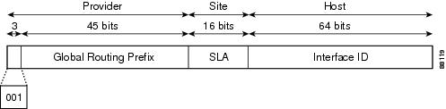
Aggregatable global IPv6 addresses are defined by a global routing prefix, a subnet ID, and an interface ID. Except for addresses that start with binary 000, all global unicast addresses have a 64-bit interface ID. The current global unicast address allocation uses the range of addresses that start with binary value 001 (2000::/3). Figure 1shows the structure of an aggregatable global address.
Addresses with a prefix of 2000::/3 (001) through E000::/3 (111) are required to have 64-bit interface identifiers in the extended universal identifier (EUI)-64 format. The Internet Assigned Numbers Authority (IANA) allocates the IPv6 address space in the range of 2000::/16 to regional registries.
The aggregatable global address typically consists of a 48-bit global routing prefix and a 16-bit subnet ID or Site-Level Aggregator (SLA). In the IPv6 aggregatable global unicast address format document (RFC 2374), the global routing prefix included two other hierarchically structured fields named Top-Level Aggregator (TLA) and Next-Level Aggregator (NLA).The IETF decided to remove the TLS and NLA fields from the RFCs, because these fields are policy-based. Some existing IPv6 networks deployed before the change might still be using networks based on the older architecture.
A 16-bit subnet field called the subnet ID could be used by individual organizations to create their own local addressing hierarchy and to identify subnets. A subnet ID is similar to a subnet in IPv4, except that an organization with an IPv6 subnet ID can support up to 65,535 individual subnets.
An interface ID is used to identify interfaces on a link. The interface ID must be unique to the link. It may also be unique over a broader scope. In many cases, an interface ID is the same as or based on the link-layer address of an interface. Interface IDs used in aggregatable global unicast and other IPv6 address types must be 64 bits long and constructed in the modified EUI-64 format.
Interface IDs are constructed in the modified EUI-64 format in one of the following ways:
For all IEEE 802 interface types (for example, Ethernet interfaces and FDDI interfaces), the first three octets (24 bits) are taken from the Organizationally Unique Identifier (OUI) of the 48-bit link-layer address (MAC address) of the interface, the fourth and fifth octets (16 bits) are a fixed hexadecimal value of FFFE, and the last three octets (24 bits) are taken from the last three octets of the MAC address. The construction of the interface ID is completed by setting the Universal/Local (U/L) bit—the seventh bit of the first octet—to a value of 0 or 1. A value of 0 indicates a locally administered identifier; a value of 1 indicates a globally unique IPv6 interface identifier.
For all other interface types (for example, serial, loopback, ATM, Frame Relay, and tunnel interface types—except tunnel interfaces used with IPv6 overlay tunnels), the interface ID is constructed in the same way as the interface ID for IEEE 802 interface types; however, the first MAC address from the pool of MAC addresses in the router is used to construct the identifier (because the interface does not have a MAC address).
For tunnel interface types that are used with IPv6 overlay tunnels, the interface ID is the IPv4 address assigned to the tunnel interface with all zeros in the high-order 32 bits of the identifier.
Note
For interfaces using Point-to-Point Protocol (PPP), given that the interfaces at both ends of the connection might have the same MAC address, the interface identifiers used at both ends of the connection are negotiated (picked randomly and, if necessary, reconstructed) until both identifiers are unique. The first MAC address in the router is used to construct the identifier for interfaces using PPP.
If no IEEE 802 interface types are in the router, link-local IPv6 addresses are generated on the interfaces in the router in the following sequence:
Link-Local Address
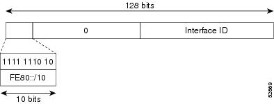
A link-local address is an IPv6 unicast address that can be automatically configured on any interface using the link-local prefix FE80::/10 (1111 1110 10) and the interface identifier in the modified EUI-64 format. Link-local addresses are used in the neighbor discovery protocol and the stateless autoconfiguration process. Nodes on a local link can use link-local addresses to communicate; the nodes do not need site-local or globally unique addresses to communicate. Figure 1shows the structure of a link-local address.
IPv6 routers must not forward packets that have link-local source or destination addresses to other links.
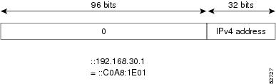
IPv4-Compatible IPv6 Address
An IPv4-compatible IPv6 address is an IPv6 unicast address that has zeros in the high-order 96 bits of the address and an IPv4 address in the low-order 32 bits of the address. The format of an IPv4-compatible IPv6 address is 0:0:0:0:0:0:A.B.C.D or ::A.B.C.D. The entire 128-bit IPv4-compatible IPv6 address is used as the IPv6 address of a node and the IPv4 address embedded in the low-order 32 bits is used as the IPv4 address of the node. IPv4-compatible IPv6 addresses are assigned to nodes that support both the IPv4 and IPv6 protocol stacks and are used in automatic tunnels. Figure 1 shows the structure of an IPv4-compatible IPv6 address and a few acceptable formats for the address.
IPv6 Address Type: Multicast
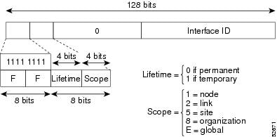
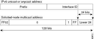
An IPv6 multicast address is an IPv6 address that has a prefix of FF00::/8 (1111 1111). An IPv6 multicast address is an identifier for a set of interfaces that typically belong to different nodes. A packet sent to a multicast address is delivered to all interfaces identified by the multicast address. The second octet following the prefix defines the lifetime and scope of the multicast address. A permanent multicast address has a lifetime parameter equal to 0; a temporary multicast address has a lifetime parameter equal to 1. A multicast address that has the scope of a node, link, site, or organization, or a global scope has a scope parameter of 1, 2, 5, 8, or E, respectively. For example, a multicast address with the prefix FF02::/16 is a permanent multicast address with a link scope. Figure 1 shows the format of the IPv6 multicast address.
IPv6 nodes (hosts and routers) are required to join (receive packets destined for) the following multicast groups:
All-nodes multicast group FF02:0:0:0:0:0:0:1 (scope is link-local)
Solicited-node multicast group FF02:0:0:0:0:1:FF00:0000/104 for each of its assigned unicast and anycast addresses
IPv6 routers must also join the all-routers multicast group FF02:0:0:0:0:0:0:2 (scope is link-local).
The solicited-node multicast address is a multicast group that corresponds to an IPv6 unicast or anycast address. IPv6 nodes must join the associated solicited-node multicast group for every unicast and anycast address to which it is assigned. The IPv6 solicited-node multicast address has the prefix FF02:0:0:0:0:1:FF00:0000/104 concatenated with the 24 low-order bits of a corresponding IPv6 unicast address. (See Figure 2.) For example, the solicited-node multicast address corresponding to the IPv6 address 2037::01:800:200E:8C6C is FF02::1:FF0E:8C6C. Solicited-node addresses are used in neighbor solicitation messages.
Note
There are no broadcast addresses in IPv6. IPv6 multicast addresses are used instead of broadcast addresses.
For further information on IPv6 multicast, refer to the Implementing Multicast module in the Cisco IOS XR Multicast Configuration Guide for the Cisco CRS Router .
Simplified IPv6 Packet Header
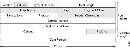
The basic IPv4 packet header has 12 fields with a total size of 20 octets (160 bits). The 12 fields may be followed by an Options field, which is followed by a data portion that is usually the transport-layer packet. The variable length of the Options field adds to the total size of the IPv4 packet header. The shaded fields of the IPv4 packet header are not included in the IPv6 packet header. (See Figure 1)
The basic IPv6 packet header has 8 fields with a total size of 40 octets (320 bits). (See Figure 2.) Fields were removed from the IPv6 header because, in IPv6, fragmentation is not handled by routers and checksums at the network layer are not used. Instead, fragmentation in IPv6 is handled by the source of a packet and checksums at the data link layer and transport layer are used. (In IPv4, the User Datagram Protocol (UDP) transport layer uses an optional checksum. In IPv6, use of the UDP checksum is required to check the integrity of the inner packet.) Additionally, the basic IPv6 packet header and Options field are aligned to 64 bits, which can facilitate the processing of IPv6 packets.
This table lists the fields in the basic IPv6 packet header.
Table 2 Basic IPv6 Packet Header Fields Field
Description
Version
Similar to the Version field in the IPv4 packet header, except that the field lists number 6 for IPv6 instead of number 4 for IPv4.
Traffic Class
Similar to the Type of Service field in the IPv4 packet header. The Traffic Class field tags packets with a traffic class that is used in differentiated services.
Flow Label
A new field in the IPv6 packet header. The Flow Label field tags packets with a specific flow that differentiates the packets at the network layer.
Payload Length
Similar to the Total Length field in the IPv4 packet header. The Payload Length field indicates the total length of the data portion of the packet.
Next Header
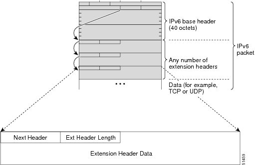
Similar to the Protocol field in the IPv4 packet header. The value of the Next Header field determines the type of information following the basic IPv6 header. The type of information following the basic IPv6 header can be a transport-layer packet, for example, a TCP or UDP packet, or an Extension Header, as shown in Figure 3.
Hop Limit
Similar to the Time to Live field in the IPv4 packet header. The value of the Hop Limit field specifies the maximum number of routers that an IPv6 packet can pass through before the packet is considered invalid. Each router decrements the value by one. Because no checksum is in the IPv6 header, the router can decrement the value without needing to recalculate the checksum, which saves processing resources.
Source Address
Similar to the Source Address field in the IPv4 packet header, except that the field contains a 128-bit source address for IPv6 instead of a 32-bit source address for IPv4.
Destination Address
Similar to the Destination Address field in the IPv4 packet header, except that the field contains a 128-bit destination address for IPv6 instead of a 32-bit destination address for IPv4.
Following the eight fields of the basic IPv6 packet header are optional extension headers and the data portion of the packet. If present, each extension header is aligned to 64 bits. There is no fixed number of extension headers in an IPv6 packet. Together, the extension headers form a chain of headers. Each extension header is identified by the Next Header field of the previous header. Typically, the final extension header has a Next Header field of a transport-layer protocol, such as TCP or UDP. Figure 3shows the IPv6 extension header format.
This table lists the extension header types and their Next Header field values.
Table 3 IPv6 Extension Header Types Header Type
Next Header Value
Description
Hop-by-hop options header
0
This header is processed by all hops in the path of a packet. When present, the hop-by-hop options header always follows immediately after the basic IPv6 packet header.
Destination options header
60
The destination options header can follow any hop-by-hop options header, in which case the destination options header is processed at the final destination and also at each visited address specified by a routing header. Alternatively, the destination options header can follow any Encapsulating Security Payload (ESP) header, in which case the destination options header is processed only at the final destination.
Routing header
43
The routing header is used for source routing.
Fragment header
44
The fragment header is used when a source must fragment a packet that is larger than the maximum transmission unit (MTU) for the path between itself and a destination. The Fragment header is used in each fragmented packet.
Authentication header
and
ESP header
51
50
The Authentication header and the ESP header are used within IP Security Protocol (IPSec) to provide authentication, integrity, and confidentiality of a packet. These headers are identical for both IPv4 and IPv6.
Upper-layer header
6 (TCP)
17 (UDP)
The upper-layer (transport) headers are the typical headers used inside a packet to transport the data. The two main transport protocols are TCP and UDP.
Mobility header
To be done by IANA
Extension headers used by mobile nodes, correspondent nodes, and home agents in all messaging related to the creation and management of bindings.
Path MTU Discovery for IPv6
As in IPv4, path MTU discovery in IPv6 allows a host to dynamically discover and adjust to differences in the MTU size of every link along a given data path. In IPv6, however, fragmentation is handled by the source of a packet when the path MTU of one link along a given data path is not large enough to accommodate the size of the packets. Having IPv6 hosts handle packet fragmentation saves IPv6 router processing resources and helps IPv6 networks run more efficiently.
Note
In IPv4, the minimum link MTU is 68 octets, which means that the MTU size of every link along a given data path must support an MTU size of at least 68 octets.
In IPv6, the minimum link MTU is 1280 octets. We recommend using an MTU value of 1500 octets for IPv6 links.
Note
Path MTU discovery is supported only for applications using the TCP transport.
IPv6 Neighbor Discovery
The IPv6 neighbor discovery process uses ICMP messages and solicited-node multicast addresses to determine the link-layer address of a neighbor on the same network (local link), verify the reachability of a neighbor, and keep track of neighboring routers.
IPv6 Neighbor Solicitation Message
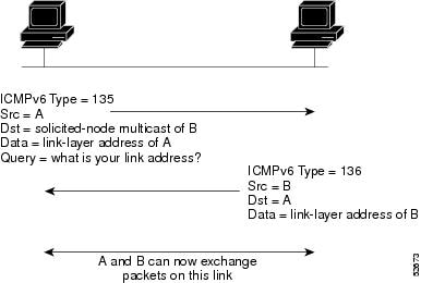
A value of 135 in the Type field of the ICMP packet header identifies a neighbor solicitation message. Neighbor solicitation messages are sent on the local link when a node wants to determine the link-layer address of another node on the same local link. (See Figure 1.) When a node wants to determine the link-layer address of another node, the source address in a neighbor solicitation message is the IPv6 address of the node sending the neighbor solicitation message. The destination address in the neighbor solicitation message is the solicited-node multicast address that corresponds to the IPv6 address of the destination node. The neighbor solicitation message also includes the link-layer address of the source node.
After receiving the neighbor solicitation message, the destination node replies by sending a neighbor advertisement message, which has a value of 136 in the Type field of the ICMP packet header, on the local link. The source address in the neighbor advertisement message is the IPv6 address of the node (more specifically, the IPv6 address of the node interface) sending the neighbor advertisement message. The destination address in the neighbor advertisement message is the IPv6 address of the node that sent the neighbor solicitation message. The data portion of the neighbor advertisement message includes the link-layer address of the node sending the neighbor advertisement message.
After the source node receives the neighbor advertisement, the source node and destination node can communicate.
Neighbor solicitation messages are also used to verify the reachability of a neighbor after the link-layer address of a neighbor is identified. When a node wants to verifying the reachability of a neighbor, the destination address in a neighbor solicitation message is the unicast address of the neighbor.
Neighbor advertisement messages are also sent when there is a change in the link-layer address of a node on a local link. When there is such a change, the destination address for the neighbor advertisement is the all-nodes multicast address.
Neighbor solicitation messages are also used to verify the reachability of a neighbor after the link-layer address of a neighbor is identified. Neighbor unreachability detection identifies the failure of a neighbor or the failure of the forward path to the neighbor, and is used for all paths between hosts and neighboring nodes (hosts or routers). Neighbor unreachability detection is performed for neighbors to which only unicast packets are being sent and is not performed for neighbors to which multicast packets are being sent.
A neighbor is considered reachable when a positive acknowledgment is returned from the neighbor (indicating that packets previously sent to the neighbor have been received and processed). A positive acknowledgment—from an upper-layer protocol (such as TCP)—indicates that a connection is making forward progress (reaching its destination) or that a neighbor advertisement message in response to a neighbor solicitation message has been received. If packets are reaching the peer, they are also reaching the next-hop neighbor of the source. Therefore, forward progress is also a confirmation that the next-hop neighbor is reachable.
For destinations that are not on the local link, forward progress implies that the first-hop router is reachable. When acknowledgments from an upper-layer protocol are not available, a node probes the neighbor using unicast neighbor solicitation messages to verify that the forward path is still working. The return of a solicited neighbor advertisement message from the neighbor is a positive acknowledgment that the forward path is still working. (Neighbor advertisement messages that have the solicited flag set to a value of 1 are sent only in response to a neighbor solicitation message.) Unsolicited messages confirm only the one-way path from the source to the destination node; solicited neighbor advertisement messages indicate that a path is working in both directions.
Note
A neighbor advertisement message that has the solicited flag set to a value of 0 must not be considered as a positive acknowledgment that the forward path is still working.
Neighbor solicitation messages are also used in the stateless autoconfiguration process to verify the uniqueness of unicast IPv6 addresses before the addresses are assigned to an interface. Duplicate address detection is performed first on a new, link-local IPv6 address before the address is assigned to an interface. (The new address remains in a tentative state while duplicate address detection is performed.) Specifically, a node sends a neighbor solicitation message with an unspecified source address and a tentative link-local address in the body of the message. If another node is already using that address, the node returns a neighbor advertisement message that contains the tentative link-local address. If another node is simultaneously verifying the uniqueness of the same address, that node also returns a neighbor solicitation message. If no neighbor advertisement messages are received in response to the neighbor solicitation message and no neighbor solicitation messages are received from other nodes that are attempting to verify the same tentative address, the node that sent the original neighbor solicitation message considers the tentative link-local address to be unique and assigns the address to the interface.
Every IPv6 unicast address (global or link-local) must be checked for uniqueness on the link; however, until the uniqueness of the link-local address is verified, duplicate address detection is not performed on any other IPv6 addresses associated with the link-local address. The Cisco implementation of duplicate address detection in the Cisco IOS XR software does not check the uniqueness of anycast or global addresses that are generated from 64-bit interface identifiers.
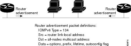
IPv6 Router Advertisement Message
Router advertisement (RA) messages, which have a value of 134 in the Type field of the ICMP packet header, are periodically sent out each configured interface of an IPv6 router. The router advertisement messages are sent to the all-nodes multicast address. (See Figure 1.)
Router advertisement messages typically include the following information:
One or more onlink IPv6 prefixes that nodes on the local link can use to automatically configure their IPv6 addresses
Lifetime information for each prefix included in the advertisement
Sets of flags that indicate the type of autoconfiguration (stateless or statefull) that can be completed
Default router information (whether the router sending the advertisement should be used as a default router and, if so, the amount of time, in seconds, that the router should be used as a default router)
Additional information for hosts, such as the hop limit and MTU a host should use in packets that it originates
Router advertisements are also sent in response to router solicitation messages. Router solicitation messages, which have a value of 133 in the Type field of the ICMP packet header, are sent by hosts at system startup so that the host can immediately autoconfigure without needing to wait for the next scheduled router advertisement message. Given that router solicitation messages are usually sent by hosts at system startup (the host does not have a configured unicast address), the source address in router solicitation messages is usually the unspecified IPv6 address (0:0:0:0:0:0:0:0). If the host has a configured unicast address, the unicast address of the interface sending the router solicitation message is used as the source address in the message. The destination address in router solicitation messages is the all-routers multicast address with a scope of the link. When a router advertisement is sent in response to a router solicitation, the destination address in the router advertisement message is the unicast address of the source of the router solicitation message.
The following router advertisement message parameters can be configured:
The time interval between periodic router advertisement messages
The “router lifetime” value, which indicates the usefulness of a router as the default router (for use by all nodes on a given link)
The network prefixes in use on a given link
The time interval between neighbor solicitation message retransmissions (on a given link)
The amount of time a node considers a neighbor reachable (for use by all nodes on a given link)
The configured parameters are specific to an interface. The sending of router advertisement messages (with default values) is automatically enabled on Ethernet and FDDI interfaces when the ipv6 unicast-routing command in global configuration mode is configured. For other interface types, the sending of router advertisement messages must be manually configured by using the no ipv6 nd suppress-ra command in global configuration mode. The sending of router advertisement messages can be disabled on individual interfaces by using the ipv6 nd suppress-ra command in interface configuration mode.
Note
For stateless autoconfiguration to work properly, the advertised prefix length in router advertisement messages must always be 64 bits.
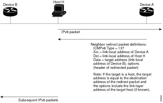
IPv6 Neighbor Redirect Message
A value of 137 in the Type field of the ICMP packet header identifies an IPv6 neighbor redirect message. Routers send neighbor redirect messages to inform hosts of better first-hop nodes on the path to a destination. (See Figure 1.)
Note
A router must be able to determine the link-local address for each of its neighboring routers to ensure that the target address (the final destination) in a redirect message identifies the neighbor router by its link-local address. For static routing, the address of the next-hop router should be specified using the link-local address of the router; for dynamic routing, all IPv6 routing protocols must exchange the link-local addresses of neighboring routers.
After forwarding a packet, a router should send a redirect message to the source of the packet under the following circumstances:
The destination address of the packet is not a multicast address.
The packet was not addressed to the router.
The packet is about to be sent out the interface on which it was received.
The router determines that a better first-hop node for the packet resides on the same link as the source of the packet.
The source address of the packet is a global IPv6 address of a neighbor on the same link, or a link-local address.
Use the ipv6 icmp error-interval global configuration command to limit the rate at which the router generates all IPv6 ICMP error messages, including neighbor redirect messages, which ultimately reduces link-layer congestion.
Note
A router must not update its routing tables after receiving a neighbor redirect message, and hosts must not originate neighbor redirect messages.
ICMP for IPv6
Internet Control Message Protocol (ICMP) in IPv6 functions the same as ICMP in IPv4—ICMP generates error messages, such as ICMP destination unreachable messages and informational messages like ICMP echo request and reply messages. Additionally, ICMP packets in IPv6 are used in the IPv6 neighbor discovery process, path MTU discovery, and the Multicast Listener Discovery (MLD) protocol for IPv6. MLD is used by IPv6 routers to discover multicast listeners (nodes that want to receive multicast packets destined for specific multicast addresses) on directly attached links. MLD is based on version 2 of the Internet Group Management Protocol (IGMP) for IPv4.
A value of 58 in the Next Header field of the basic IPv6 packet header identifies an IPv6 ICMP packet. ICMP packets in IPv6 are like a transport-layer packet in the sense that the ICMP packet follows all the extension headers and is the last piece of information in the IPv6 packet. Within IPv6 ICMP packets, the ICMPv6 Type and ICMPv6 Code fields identify IPv6 ICMP packet specifics, such as the ICMP message type. The value in the Checksum field is derived (computed by the sender and checked by the receiver) from the fields in the IPv6 ICMP packet and the IPv6 pseudoheader. The ICMPv6 Data field contains error or diagnostic information relevant to IP packet processing.
Address Repository Manager
IPv4 and IPv6 Address Repository Manager (IPARM) enforces the uniqueness of global IP addresses configured in the system, and provides global IP address information dissemination to processes on route processors (RPs) and line cards (LCs) using the IP address consumer application program interfaces (APIs), which includes unnumbered interface information.
Address Conflict Resolution
There are two parts to conflict resolution; the conflict database and the conflict set definition.
Conflict Database
IPARM maintains a global conflict database. IP addresses that conflict with each other are maintained in lists called conflict sets. These conflict sets make up the global conflict database.
A set of IP addresses are said to be part of a conflict set if at least one prefix in the set conflicts with every other IP address belonging to the same set. For example, the following four addresses are part of a single conflict set.
address 1: 10.1.1.1/16
address 2: 10.2.1.1/16
address 3: 10.3.1.1/16
address 4: 10.4.1.1/8
When a conflicting IP address is added to a conflict set, an algorithm runs through the set to determine the highest precedence address within the set.
This conflict policy algorithm is deterministic, that is, the user can tell which addresses on the interface are enabled or disabled. The address on the interface that is enabled is declared as the highest precedence ip address for that conflict set.
The conflict policy algorithm determines the highest precedence ip address within the set.
Multiple IP Addresses
The IPARM conflict handling algorithm allows multiple IP addresses to be enabled within a set. Multiple addresses could potentially be highest precedence IP addresses.
interface GigabitEthernet 0/2/0/0: 10.1.1.1/16
interface GigabitEthernet 0/3/0/0: 10.1.1.2/8
interface GigabitEthernet 0/4/0/0: 10.2.1.1/16
The IP address on GigabitEthernet 0POS0/2/0/0 is declared as highest precedence as per the lowest rack/slot policy and is enabled. However, because the address on interface GigabitEthernet 0/4/0/0 does not conflict with the current highest precedence IP address, the address on GigabitEthernet 0/4/0/0 is enabled as well.
Recursive Resolution of Conflict Sets
In the example below, the address on the interface in GigabitEthernet 0/2/0/0 has the highest precedence because it is the lowest rack/slot. However, now the addresses on GigabitEthernet 0/4/0/0 and GigabitEthernet 0/5/0/0 also do not conflict with the highest precedence IP addresses on GigabitEthernet 0/2/0/0. However, the addresses on Gigabitethernet 0/4/0/0 and GigabitEthernet 0/5/0/0 do; which one gets enabled? The conflict resolution software tries to keep the interface that is enabled as the one that needs to stay enabled. If both interfaces are disabled, the software enables the address based on the current conflict policy. Because GigabitEthernet 0/4/0/0 is on a lower rack/slot, it is enabled.
interface GigabitEthernet 0/2/0/0: 10.1.1.1/16
interface GigabitEthernet 0/3/0/0: 10.1.1.2/8
interface GigabitEthernet 0/4/0/0: 10.2.1.1/16
interface GigabitEthernet 0/5/0/0: 10.2.1.2/16
Route-Tag Support for Connected Routes
SUMMARY STEPSThe Route-Tag Support for Connected Routes feature that attaches a tag with all IPv4 and IPv6 addresses of an interface. The tag is propagated from the IPv4 and IPv6 management agents (MA) to the IPv4 and IPv6 address repository managers (ARM) to routing protocols, thus enabling the user to control the redistribution of connected routes by looking at the route tags, by using routing policy language (RPL) scripts. This prevents the redistribution of some interfaces, by checking for route tags in a route policy.
The route tag feature is already available for static routes and connected routes(interfaces) wherein the route tags are matched to policies and redistribution can be prevented.
2. interface type interface-path-id
4. route-tag [ route-tag value ]
5. Use one of the following commands:
DETAILED STEPSHow to Implement Network Stack IPv4 and IPv6
This section contains the following procedures:
- Assigning IPv4 Addresses to Network Interfaces
- Configuring IPv6 Addressing
- Assigning Multiple IP Addresses to Network Interfaces
- Configuring IPv4 and IPv6 Protocol Stacks
- Enabling IPv4 Processing on an Unnumbered Interface
- Configuring ICMP Rate Limiting
- Configuring IPARM Conflict Resolution
Assigning IPv4 Addresses to Network Interfaces
This task assigns IPv4 addresses to individual network interfaces.
IPv4 Addresses
SUMMARY STEPSA basic and required task for configuring IP is to assign IPv4 addresses to network interfaces. Doing so enables the interfaces and allows communication with hosts on those interfaces using IPv4. An IP address identifies a location to which IP datagrams can be sent. An interface can have one primary IP address and multiple secondary addresses. Packets generated by the software always use the primary IPv4 address. Therefore, all networking devices on a segment should share the same primary network number.
Associated with this task are decisions about subnetting and masking the IP addresses. A mask identifies the bits that denote the network number in an IP address. When you use the mask to subnet a network, the mask is then referred to as a subnet mask.
Note
Cisco supports only network masks that use contiguous bits that are flush left against the network field.
2. interface type interface-path-id
3. ipv4 address ipv4-address mask [secondary]
4. Use one of the following commands:
DETAILED STEPSIPv4 Virtual Addresses
Configuring an IPv4 virtual address enables you to access the router from a single virtual address with a management network, without the prior knowledge of which route processor (RP) is active. An IPv4 virtual address persists across RP failover situations. For this to happen, the virtual IPv4 address must share a common IPv4 subnet with a Management Ethernet interface on both RPs.
The vrf keyword supports virtual addresses on a per-VRF basis.
The use-as-src-addr keyword eliminates the need for configuring a loopback interface as the source interface (that is, update source) for management applications. When an update source is not configured, management applications allow the transport processes (TCP, UDP, raw_ip) to select a suitable source address. The transport processes, in turn, consult the FIB for selecting a suitable source address. If a Management Ethernet's IP address is selected as the source address and if the use-as-src-addr keyword is configured, then the transport substitutes the Management Ethernet's IP address with a relevant virtual IP address. This functionality works across RP switchovers. If the use-as-src-addr is not configured, then the source-address selected by transports can change after a failover and the NMS software may not be able to manage this situation.
Note
Protocol configuration such as tacacs source-interface, snmp-server trap-source, ntp source, logging source-interface do not use the virtual management IP address as their source by default. Use the ipv4 virtual address use-as-src-addr command to ensure that the protocol uses the virtual IPv4 address as its source address. Alternatively, you can also configure a loopback address with the designated or desired IPv4 address and set that as the source for protocols such as TACACS+ via the tacacs source-interface command.
Configuring IPv6 Addressing
This task assigns IPv6 addresses to individual router interfaces and enable the forwarding of IPv6 traffic globally on the router. By default, IPv6 addresses are not configured.
Note
The ipv6-prefix argument in the ipv6 address command must be in the form documented in RFC 2373 in which the address is specified in hexadecimal using 16-bit values between colons.
The /prefix-length argument in the ipv6 address command is a decimal value that indicates how many of the high-order contiguous bits of the address comprise the prefix (the network portion of the address) A slash must precede the decimal value.
The ipv6-address argument in the ipv6 address link-local command must be in the form documented in RFC 2373 where the address is specified in hexadecimal using 16-bit values between colons.
IPv6 Multicast Groups
SUMMARY STEPSAn IPv6 address must be configured on an interface for the interface to forward IPv6 traffic. Configuring a global IPv6 address on an interface automatically configures a link-local address and activates IPv6 for that interface.
Additionally, the configured interface automatically joins the following required multicast groups for that link:
2. interface type interface-path-id
4. Use one of the following commands:
DETAILED STEPSAssigning Multiple IP Addresses to Network Interfaces
This task assigns multiple IP addresses to network interfaces.
Secondary IPv4 Addresses
SUMMARY STEPSThe Cisco IOS XR software supports multiple IP addresses per interface. You can specify an unlimited number of secondary addresses. Secondary IP addresses can be used in a variety of situations. The following are the most common applications:
There might not be enough host addresses for a particular network segment. For example, suppose your subnetting allows up to 254 hosts per logical subnet, but on one physical subnet you must have 300 host addresses. Using secondary IP addresses on the routers or access servers allows you to have two logical subnets using one physical subnet.
Many older networks were built using Level 2 bridges, and were not subnetted. The judicious use of secondary addresses can aid in the transition to a subnetted, router-based network. Routers on an older, bridged segment can easily be made aware that many subnets are on that segment.
Two subnets of a single network might otherwise be separated by another network. You can create a single network from subnets that are physically separated by another network by using a secondary address. In these instances, the first network is extended, or layered on top of the second network. Note that a subnet cannot appear on more than one active interface of the router at a time.
Note
If any router on a network segment uses a secondary IPv4 address, all other routers on that same segment must also use a secondary address from the same network or subnet.
Caution
Inconsistent use of secondary addresses on a network segment can quickly cause routing loops.
2. interface type interface-path-id
3. ipv4 address ipv4-address mask [secondary]
4. Use one of the following commands:
DETAILED STEPSConfiguring IPv4 and IPv6 Protocol Stacks
SUMMARY STEPSThis task configures an interface in a Cisco networking device to support both the IPv4 and IPv6 protocol stacks.
When an interface in a Cisco networking device is configured with both an IPv4 and an IPv6 address, the interface forwards both IPv4 and IPv6 traffic—the interface can send and receive data on both IPv4 and IPv6 networks.
2. interface type interface-path-id
3. ipv4 address ip-address mask [secondary]
4. ipv6 address ipv6-prefix/prefix-length [eui-64]
5. Use one of the following commands:
DETAILED STEPSEnabling IPv4 Processing on an Unnumbered Interface
This task enables IPv4 processing on an unnumbered interface.
IPv4 Processing on an Unnumbered Interface
SUMMARY STEPSThis section describes the process of enabling an IPv4 point-to-point interface without assigning an explicit IP address to the interface. Whenever the unnumbered interface generates a packet (for example, for a routing update), it uses the address of the interface you specified as the source address of the IP packet. It also uses the specified interface address in determining which routing processes are sending updates over the unnumbered interface. Restrictions are as follows:
Serial interfaces using High-Level Data Link Control (HDLC), PPP, and Frame Relay encapsulations can be unnumbered. Serial interfaces using Frame Relay encapsulation can also be unnumbered, but the interface must be a point-to-point subinterface.
You cannot use the ping EXEC command to determine whether the interface is up, because the interface has no IP address. The Simple Network Management Protocol (SNMP) can be used to remotely monitor interface status.
You cannot support IP security options on an unnumbered interface.
If you are configuring Intermediate System-to-Intermediate System (IS-IS) across a serial line, you should configure the serial interfaces as unnumbered, which allows you to conform with RFC 1195, which states that IP addresses are not required on each interface.
2. interface type interface-path-id
3. ipv4 unnumbered interface-type interface-instance
4. Use one of the following commands:
DETAILED STEPSConfiguring ICMP Rate Limiting
This task explains how to configure IPv4 or IPv6 ICMP rate limiting.
IPv4 ICMP Rate Limiting
The IPv4 ICMP rate limiting feature limits the rate that IPv4 ICMP destination unreachable messages are generated. The Cisco IOS XR software maintains two timers: one for general destination unreachable messages and one for DF destination unreachable messages. Both share the same time limits and defaults. If the DF keyword is not configured, the icmp ipv4 rate-limit unreachable command sets the time values for DF destination unreachable messages. If the DF keyword is configured, its time values remain independent from those of general destination unreachable messages.
IPv6 ICMP Rate Limiting
SUMMARY STEPSThe IPv6 ICMP rate limiting feature implements a token bucket algorithm for limiting the rate at which IPv6 ICMP error messages are sent out on the network. The initial implementation of IPv6 ICMP rate limiting defined a fixed interval between error messages, but some applications, such as traceroute, often require replies to a group of requests sent in rapid succession. The fixed interval between error messages is not flexible enough to work with applications such as traceroute and can cause the application to fail. Implementing a token bucket scheme allows a number of tokens—representing the ability to send one error message each—to be stored in a virtual bucket. The maximum number of tokens allowed in the bucket can be specified, and for every error message to be sent, one token is removed from the bucket. If a series of error messages is generated, error messages can be sent until the bucket is empty. When the bucket is empty of tokens, IPv6 ICMP error messages are not sent until a new token is placed in the bucket. The token bucket algorithm does not increase the average rate limiting time interval, and it is more flexible than the fixed time interval scheme.
3. Use one of the following commands:
DETAILED STEPSConfiguring IPARM Conflict Resolution
This task sets the IP Address Repository Manager (IPARM) address conflict resolution parameters.
- Static Policy Resolution
- Longest Prefix Address Conflict Resolution
- Highest IP Address Conflict Resolution
Static Policy Resolution
SUMMARY STEPSThe static policy resolution configuration prevents new address configurations from affecting interfaces that are currently running.
2. {ipv4 | ipv6} conflict-policy static
3. Use one of the following commands:
DETAILED STEPSLongest Prefix Address Conflict Resolution
SUMMARY STEPSThis conflict resolution policy attempts to give highest precedence to the IP address that has the longest prefix length.
2. { ipv4 | ipv6 } conflict-policy longest-prefix
3. Use one of the following commands:
DETAILED STEPSHighest IP Address Conflict Resolution
SUMMARY STEPSThis conflict resolution policy attempts to give highest precedence to the IP address that has the highest value.
2. { ipv4 | ipv6 } conflict-policy highest-ip
3. Use one of the following commands:
DETAILED STEPSGeneric Routing Encapsulation
Generic Routing Encapsulation (GRE) tunneling protocol provides a simple, generic approach to transport packets of one protocol over another protocol by means of encapsulation. The packet that needs to be transported is first encapsulated in a GRE header, which is further encapsulated in another protocol like IPv4 or IPv6 and then forwarded to the destination.
A typical GRE-encapsulated packet includes:
The delivery header
The GRE header
The payload packet
A system has a packet that needs to be encapsulated and delivered to a destination. This is the payload packet. The payload is first encapsulated in a GRE packet. The resulting GRE packet can then be encapsulated in another protocol and then forwarded. This outer protocol is called the delivery protocol.
Note
When IPv4 is being carried as the GRE payload, the Protocol Type field must be set to 0x800. IPv6 as delivery and/or payload protocol is not included in the currently deployed versions of GRE.
IPv4 forwarding over GRE tunnels
The packets that are tunneled over GRE tunnels enter the router as normal IP packets. The packets are forwarded (routed) using the destination address of the IP packet. In case of Equal Cost Multi Path (ECMP) scenarios, an output interface/adjacency is selected based on platform specific L3 load balance (LB) hash. In case of two stage forwarding platforms like CRS, the receive-adjacency of the selected output interface is used to get the packet to the egress line card that hosts the interface. If the selected output interface is a GRE interface, the ingress line card has to determine the actual physical interface that can be used to reach the GRE tunnel destination. For this, second routing (forwarding) decision is made based on the GRE tunnel destination address where L3 load balance hash is applied again to determine the physical interface. Once egress physical is known, the packet is sent out of that interface after it is first encapsulated with GRE header followed by the L2 rewrite header of the physical interface. After the GRE encapsulated packet reaches the remote tunnel endpoint router, the GRE packet is decapsulated. The lookup for destination address of the outer IP header (which is the same as the tunnel destination address) will find a local address (receive) entry on the ingress line card.
The first step in GRE decapsulation is to qualify the tunnel endpoint based on the combination of tunnel source (same as source IP address of outer IP header) and tunnel destination (same as destination IP address of outer IP header) before admitting the GRE packet into the router. If the received packet fails tunnel admittance qualification check, the packet is dropped by the decapsulation router. On successful tunnel admittance check, the decapsulation strips the outer IP and GRE header off the packet, then starts processing the inner payload packet as a regular packet.
When a tunnel endpoint decapsulates a GRE packet which has an IPv4 packet as the payload, the destination address in the IPv4 payload packet header must be used to forward the packet and the TTL of the payload packet must be decremented. Care should be taken when forwarding such a packet. If the destination address of the payload packet is the encapsulator of the packet (i.e., the other end of the tunnel), looping can occur. In this case, the packet must be discarded.
IPv6 forwarding over GRE tunnels
IPv6 forwarding over GRE is accomplished by IPv6 forwarding over IPv4 GRE tunnels. The functionality is similar to the IPv4 forwarding over GRE tunnels (as described above). In the case of IPv6, the FIM (Forward Information Base) module needs to confirm if the forwarding chain is correctly setup both in slowpath and hardware to send the IPv6 packet as a payload of IPv4 GRE encapsulated packet.
Configuration Examples for Implementing Network Stack IPv4 and IPv6
- Creating a Network from Separated Subnets: Example
- Assigning an Unnumbered Interface: Example
- Configuring Helper Addresses: Example
Creating a Network from Separated Subnets: Example
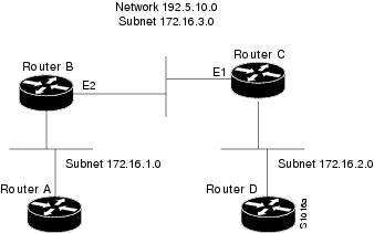
In the following example, subnets 1 and 2 of network 172.16.0.0 are separated by a backbone, as shown in Figure 1. The two networks are brought into the same logical network through the use of secondary addresses.The following examples show the configurations for routers B and C:
Assigning an Unnumbered Interface: Example
In the following example, the second interface (GigabitEthernet 0/1/0/1) is given the address of loopback interface 0. The loopback interface is unnumbered.
interface loopback 0
 ipv4 address 192.168.0.5 255.255.255.0
interface gigabitethernet 0/1/0/1
 ipv4 unnumbered loopback 0
Configuring Helper Addresses: Example
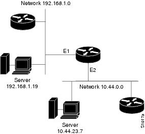
In the following example, one router is on network 192.168.1.0 and the other is on network 10.44.0.0, and you want to permit IP broadcasts from hosts on either network segment to reach both servers. Figure 1illustrates how to configure the router that connects network 10.44.0.0 to network 192.168.1.0.
The following example shows the configuration:
!
interface gigabitethernet 0/0/0/1
 ipv4 helper-address 10.44.23.7
interface gigabitethernet 0/0/0/2
 ipv4 helper-address 192.168.1.19
Additional References
Related Documents
Related Topic
Document Title
Address resolution configuration tasks
Configuring ARP module in this publication.
Mapping host names to IP addresses
Host Services and Applications Commands module in the Cisco IOS XR IP Addresses and Services Command Reference for the Cisco CRS Router
Network stack IPv4 and IPv6 commands: complete command syntax, command modes, command history, defaults, usage guidelines, and examples
Network Stack IPv4 and IPv6 Commands section in the Cisco IOS XR IP Addresses and Services Command Reference for the Cisco CRS Router
MIBs
MIBs
MIBs Link
— To locate and download MIBs using Cisco IOS XR software, use the Cisco MIB Locator found at the following URL and choose a platform under the Cisco Access Products menu: http://cisco.com/public/sw-center/netmgmt/cmtk/mibs.shtml