Connected Grid Antennas Installation Guide
Bias-Free Language
The documentation set for this product strives to use bias-free language. For the purposes of this documentation set, bias-free is defined as language that does not imply discrimination based on age, disability, gender, racial identity, ethnic identity, sexual orientation, socioeconomic status, and intersectionality. Exceptions may be present in the documentation due to language that is hardcoded in the user interfaces of the product software, language used based on RFP documentation, or language that is used by a referenced third-party product. Learn more about how Cisco is using Inclusive Language.
- Updated:
- March 23, 2012
Chapter: Cisco Multiband Panel Outdoor 3G Antenna (ANT-3G-PNL-OUT-N)
Cisco Multiband Panel Outdoor 3G Antenna (ANT-3G-PNL-OUT-N)
The Multiband Panel Outdoor 3G antenna is designed to cover cellular 3G bands and is supported on the Cisco CGR 1240 and the 1120 routers. This document provides the antenna specifications and mounting instructions.

Technical Specifications
The Multiband Panel Outdoor 3G directional panel antenna features the following:
- Flame retardant
- Low-profile housing
- Indoor and outdoors
- Adjustable mounting brackets
- Type N female connector
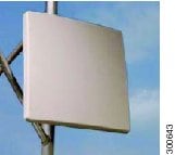
Figure 5-1 Multiband Panel Outdoor 3G Antenna
Contents of the Antenna Kit
The contents of the multi-purpose integrated antenna are listed in Table 5-1 :
Safety Warnings

Warning Avoid using or servicing any equipment that has outdoor connections during an electrical storm.
There may be a risk of electric shock from lightning. Statement 1088
Warning Do not work on the system, or connect or disconnect cables, during periods of lightning activity. Statement 1001
Warning Do not locate the outdoor antenna near overhead power lines or other electric light or power circuits, or where it can come into contact with such circuits. When installing the antenna, take extreme care not to come into contact with such circuits, as they may cause serious injury or death. For proper installation and grounding of the antenna, please refer to national and local codes (for example, U.S.:NFPA 70, National Electrical Code, Article 810, Canada:Canadian Electrical Code, Section 54). Statement 1052
Warning This equipment must be grounded. Never defeat the ground conductor or operate the equipment in the absence of a suitably installed ground conductor. Contact the appropriate electrical inspection authority or an electrician if you are uncertain that suitable grounding is available. Statement 1024
Warning Only trained and qualified personnel should be allowed to install, replace, or service this equipment. Statement 1030
Warning To report a gas leak, do not use a telephone in the vicinity of the leak. Statement 1039
Warning This warning symbol means danger. You are in a situation that could cause bodily injury. Before you work on any equipment, be aware of the hazards involved with electrical circuitry and be familiar with standard practices for preventing accidents. Use the statement number provided at the end of each warning to locate its translation in the translated safety warnings that accompanied this device. Statement 1071. SAVE THESE INSTRUCTIONS.
Warning This product is not intended to be directly connected to the Cable Distribution System. Additional regulatory compliance and legal requirements may apply for direct connection to the Cable Distribution System. This product may connect to the Cable Distribution System ONLY through a device that is approved for direct connection. Statement 1078
Warning This warning symbol means danger. You are in a situation that could cause bodily injury. Before you work on any equipment, be aware of the hazards involved with electrical circuitry and be familiar with standard practices for preventing accidents.
Safety Precautions
Warning Installation of this antenna near power lines is dangerous. For your safety, follow the installation directions.
Each year hundreds of people are killed or injured when attempting to install an antenna. In many of these cases, the victim was aware of the danger of electrocution, but did not take adequate steps to avoid the hazard.
For your safety, and to help you achieve a good installation, please read and follow these safety precautions. They may save your life!
For your safety, read and follow these safety precautions.
- If you are installing an antenna for the first time, for your own safety as well as others, seek professional assistance. Your Cisco sales representative can explain which mounting method to use for the size and type antenna you are about to install.
- Before you install an antenna, contact your Cisco account representative to explain which mounting method to use for the size and type of antenna that you are about to install.
- Find someone to help you—installing an antenna is often a two-person job.
- Select your installation site with safety, as well as performance, in mind. Remember that electric power lines and phone lines look alike. For your safety, assume that any overhead line can kill you.
- Contact your electric power company. Tell them your plans and ask them to come look at your proposed installation.
- Plan your installation carefully and completely before you begin. Each person involved in an installation should be assigned to a specific task, and should know what to do and when to do it. One person should be in charge of the operation to issue instructions and watch for signs of trouble.
- When installing your antenna, follow these guidelines:
– Do not work on a wet or windy day.
– Do dress properly—wear shoes with rubber soles and heels, rubber gloves, and a long-sleeved shirt or jacket.
- If the assembly starts to drop, move away from it and let it fall. Because the antenna, mast, cable, and metal guy wires are all excellent conductors of electrical current, even the slightest touch of any of these parts to a power line completes an electrical path through the antenna and the installer.
- If any part of the antenna system should come in contact with a power line, do not touch it or try to remove it yourself. Call your local power company to have it removed safely.
- If an accident should occur with the power lines, call for qualified emergency help immediately.
Antenna Installation
The antenna installation includes the following procedures:
Tools and Equipment Required
In addition to the parts included in the antenna kit described in the section Contents of the Antenna Kit, you must provide the following tool to install the antenna on the router:
- A flathead screwdriver
- 3/4 in. open-end wrench
- LMR-400 with male end-to-end RF cable (weatherized)
- Coax seal

Note This list does not include the tools and equipment required to assemble and erect the tower, mast, or other structure you intend to mount your antenna on.
Installing the Antenna
Follow these instructions to install the antenna:
Step 1 Choose the mounting polarization configuration that you prefer.
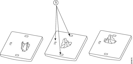
Note Your connector type, location and quantity might differ from what is shown.
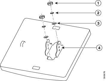
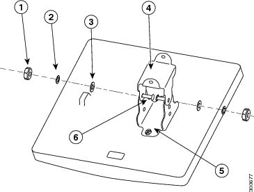
Step 2 Attach the antenna mount bracket to the back of the antenna by using two sets of flat washers, lock washers, and hex nuts. Tighten the nut to a torque rating of 55 in-lbf (6.2 Nm).
Step 3 Attach the elevation adjustable bracket to the mount bracket using two sets of carriage bolts, washers, lock washers, and hex nuts. Position the bolts so the carriage bolt square holes are positioned on the inside. Do not tighten fully. Allow the bracket to move freely.
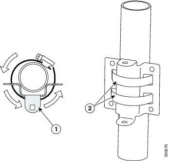
Step 4 Position the azimuth adjustable (pipe) bracket to the pipe with the flanges away from the pipe. Secure each bracket to the pipe first by routing the band clamps around the pipe, then through the two holes. Tighten to a maximum torque rating.
Step 5 Attach the antenna assembly to the installed azimuth bracket. Position each of the two flanges on elevation adjustable bracket (on the antenna) over the flanges on the azimuth (pipe) bracket.
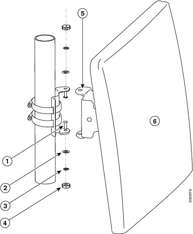
Step 6 Adjust to the desired azimuth and elevation angles. Tighten all nuts and bolts to a torque rating of 55 in-lbf.
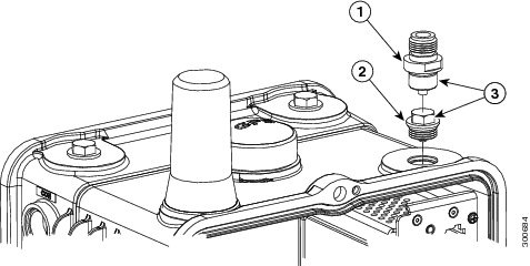
Step 7 Attach the lightning arrestor to the router. See Cisco Lightning Arrestors.
Step 8 Attach the RF cable to the antenna by connecting the ends of the LMR-400 cables to the two receptacles on the rear of the antenna panel. For more information on antenna ports, see Antenna Ports.
Note The 3G panel has only one connector per antenna.
Step 9 Seal the cable connections on the router and the back of the antenna by using weatherproof sealing tape (coax seal) at the connector junction. Start wrapping at the top of the antenna connector, wrap downward 3 times and end about 2 inches downward from the center of the connecter junction. Then wrap upwards another 3 times to reach the top of the antenna connector.
Step 10 Attach the router-end of the cable to your router. See Connect the Antenna-to-Module Cable in the CGR 1240 in Chapter 1, “Cisco CGR 1000 and 2000 Series Connected Grid Antennas Overview”.
Connecting the Lightning Arrestor
To install a lightning-protection device, seeCisco Lightning Arrestors in Chapter 1, “Cisco CGR 1000 and 2000 Series Connected Grid Antennas Overview”.
Connecting the Antenna to the Router
To attach the router-end of the cable to your router, see Connecting the Antenna to the CGR 1120 in Chapter 1, “Cisco CGR 1000 and 2000 Series Connected Grid Antennas Overview”.
Obtaining Documentation and Submitting a Service Request
For information on obtaining documentation, submitting a service request, and gathering additional information, see the monthly What’s New in Cisco Product Documentation, which also lists all new and revised Cisco technical documentation, at:
http://www.cisco.com/en/US/docs/general/whatsnew/whatsnew.html
Subscribe to the What’s New in Cisco Product Documentation as an RSS (Really Simple Syndication) feed, and set it so content is delivered directly to your desktop using a reader application. The RSS feeds are a free service and Cisco currently supports RSS Version 2.0.
 Feedback