Trunk circuits
connect telephone switches to one another; they do not connect end-user
equipment to the network. The most common form of analog trunk circuit is the
E&M interface, which uses special signaling paths that are separate from
the trunk’s audio path to convey information about the calls. The signaling
paths are known as the
E-lead and the
M-lead. The name
E&M is
thought to derive from the phrase
Ear
and Mouth
or
rEceive and
transMit
although it could also come from
Earth
and Magnet.
The history of these names dates back to the days of telegraphy, when the CO
side had a key that grounded the E circuit, and the other side had a sounder
with an electromagnet attached to a battery. Descriptions such as
Ear and
Mouth were
adopted to help field personnel determine the direction of a signal in a wire.
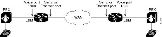
E&M connections from routers to telephone switches or to PBXs are
preferable to FXS/FXO connections because E&M provides better answer and
disconnect supervision.
Like a serial port,
an E&M interface has a data terminal equipment/data communications
equipment (DTE/DCE) type of reference. In telecommunications, the
trunking side is
similar to the DCE, and is usually associated with CO functionality. The router
acts as this side of the interface. The other side is referred to as the
signaling side,
like a DTE, and is usually a device such as a PBX. Five distinct physical
configurations for the signaling part of the interface (Types I-V) use
different methods to signal on-hook/off-hook status, as shown in the table
below. Cisco voice implementation supports E&M Types I, II, III, and V.
Table 1. EandM Wiring and Signaling
Methods
|
E&M Type
|
E-Lead
Configuration
|
M-Lead
Configuration
|
Signal
Battery Lead Configuration
|
Signal Ground
Lead Configuration
|
|
I
|
Output, relay
to ground
|
Input,
referenced to ground
|
--
|
--
|
|
II
|
Output, relay
to SG
|
Input,
referenced to ground
|
Feed for M,
connected to -48V
|
Return for E,
galvanically isolated from ground
|
|
III
|
Output, relay
to ground
|
Input,
referenced to ground
|
Connected to
-48V
|
Connected to
ground
|
|
V
|
Output, relay
to ground
|
Input,
referenced to -48V
|
--
|
--
|
The physical E&M
interface is an RJ-48 connector that connects to PBX trunk lines, which are
classified as either two-wire or four-wire. This refers to whether the audio
path is full duplex on one pair of wires (two-wire) or on two pair of wires
(four-wire). A connection may be called a four-wire E&M circuit although it
actually has six to eight physical wires. It is an analog connection although
an analog E&M circuit may be emulated on a digital line.
PBXs built by
different manufacturers can indicate on-hook/off-hook status and telephone line
seizure on the E&M interface by using any of the following three types of
access signaling:
-
Immediate-start
is the simplest method of E&M access signaling. The calling side seizes the
line by going off-hook on its E-lead and sends address information as dual-tone
multifrequency (DTMF) digits
following a short, fixed-length pause.
-
Wink-start is the
most commonly used method for E&M access signaling, and is the default for
E&M voice ports. Wink-start was developed to minimize glare, a condition
found in immediate-start E&M, in which both ends attempt to seize a trunk
at the same time. In wink-start, the calling side seizes the line by going
off-hook on its E-lead, then waits for a short temporary off-hook pulse, or
"wink," from the other end on its M-lead before sending address information.
The switch interprets the pulse as an indication to proceed and then sends the
dialed digits as DTMF or dialed pulses.
-
In delay-dial
signaling, the calling station seizes the line by going off-hook on its E-lead.
After a timed interval, the calling side looks at the status of the called
side. If the called side is on-hook, the calling side starts sending
information as DTMF digits; otherwise, the calling side waits until the called
side goes on-hook and then starts sending address information.

 Feedback