Cisco IAD2801 Integrated Access Device Hardware Installation Guide
Bias-Free Language
The documentation set for this product strives to use bias-free language. For the purposes of this documentation set, bias-free is defined as language that does not imply discrimination based on age, disability, gender, racial identity, ethnic identity, sexual orientation, socioeconomic status, and intersectionality. Exceptions may be present in the documentation due to language that is hardcoded in the user interfaces of the product software, language used based on RFP documentation, or language that is used by a referenced third-party product. Learn more about how Cisco is using Inclusive Language.
- Updated:
- August 3, 2007
Chapter: Chassis Installation Procedures
Chassis Installation Procedures
This document describes how to install your Cisco IAD2801 on a desktop or in a rack. It includes the following sections:
•![]() Installing the Chassis Ground Connection
Installing the Chassis Ground Connection

Warning ![]() Only trained and qualified personnel should be allowed to install, replace, or service this equipment. Statement 1030
Only trained and qualified personnel should be allowed to install, replace, or service this equipment. Statement 1030
Warning ![]() This unit is intended for installation in restricted access areas. A restricted access area can be accessed only through the use of a special tool, lock and key, or other means of security. Statement 1017
This unit is intended for installation in restricted access areas. A restricted access area can be accessed only through the use of a special tool, lock and key, or other means of security. Statement 1017
Setting Up the Chassis
You can set any Cisco IAD2801 on a desktop or install it in a rack. See the applicable instructions in the following sections.
•![]() Setting the Chassis on a Desktop
Setting the Chassis on a Desktop

Warning ![]() Before working on a system that has an on/off switch, turn OFF the power and unplug the power cord. Statement 1
Before working on a system that has an on/off switch, turn OFF the power and unplug the power cord. Statement 1
Rack-Mounting the Chassis
If you are planning to rack-mount the router, do so before making network and power connections. Internal modules should be installed prior to rack-mounting.
Cisco IAD2801 series integrated access devices can be installed only in 19-inch racks, and cannot be center mounted. Use the standard brackets shipped with the router for mounting the chassis in a 19-inch rack.

Note ![]() Brackets for 23-inch (58.42-cm) equipment racks are not available for the Cisco IAD2801.
Brackets for 23-inch (58.42-cm) equipment racks are not available for the Cisco IAD2801.
You can mount the router in the following ways:
•![]() Front mounting—Brackets attached at the front of the chassis with the front panel facing forward.
Front mounting—Brackets attached at the front of the chassis with the front panel facing forward.
•![]() Rear mounting—Brackets attached at the rear of the chassis with the rear panel facing forward.
Rear mounting—Brackets attached at the rear of the chassis with the rear panel facing forward.
The brackets are shown in Figure 4-1.
Figure 4-1 Rack-Mounting Brackets for the Cisco IAD2801 for a 19-Inch Rack
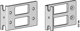
Attaching Rack-Mount Brackets to Cisco IAD2801 Series Integrated Access Devices
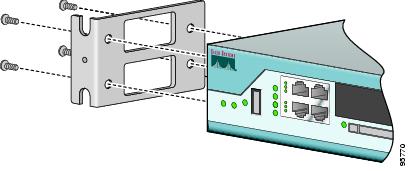
Use four of the supplied number-8 Phillips flat-head screws to attach the long side of each bracket to the router. Figure 4-2 shows how to attach the brackets to the sides of the router with the front panel forward.
Figure 4-2 Attaching Rack-Mounting Brackets to a Cisco IAD2801
Installing the Router in a Rack
After you have attached the brackets to the router chassis, use the screws provided with the rack to install the chassis in the rack.

Tip ![]() Start the lower pair of screws first, and rest the brackets on the lower screws while you insert the upper pair of screws.
Start the lower pair of screws first, and rest the brackets on the lower screws while you insert the upper pair of screws.
Tip ![]() The screw slots in the brackets are spaced to line up with every second pair of screw holes in the rack. When the correct screw holes are used, the small threaded holes in the brackets line up with unused screw holes in the rack. If the small holes do not line up with the rack holes, you must raise or lower the brackets to the next rack hole.
The screw slots in the brackets are spaced to line up with every second pair of screw holes in the rack. When the correct screw holes are used, the small threaded holes in the brackets line up with unused screw holes in the rack. If the small holes do not line up with the rack holes, you must raise or lower the brackets to the next rack hole.
Attaching Optional Cable Management Bracket
The optional cable management bracket provides attachment points for organizing and routing cables. On brackets for the Cisco IAD2801, attach the cable management bracket to the left or right rack-mount bracket using the screw provided, as shown in Figure 4-3.
Figure 4-3 Attaching the Optional Cable Management Bracket to the Cisco IAD2801

Chassis Grounding
After the router is installed, you must connect the chassis to a reliable earth ground. For the chassis ground connection procedures, see the "Installing the Chassis Ground Connection" section.
Setting the Chassis on a Desktop
You can place a Cisco IAD2801 on a desktop or shelf. If you are placing a Cisco IAD2801 on a desktop, you must first install the four rubber feet that are supplied in the accessory kit. They provide space for air circulation and antiskid protection. Peel the rubber feet from the adhesive strip, and stick them onto the features marked "+" on the bottom of the chassis.
Warning ![]() To prevent personal injury or damage to the chassis, never attempt to lift or tilt the chassis using the handles on modules (such as power supplies, fans, or cards); these types of handles are not designed to support the weight of the unit. Statement 1032
To prevent personal injury or damage to the chassis, never attempt to lift or tilt the chassis using the handles on modules (such as power supplies, fans, or cards); these types of handles are not designed to support the weight of the unit. Statement 1032
10 pounds on top could damage the chassis.
After the router is installed, you must connect the chassis to a reliable earth ground. For the chassis ground connection procedures, see the "Installing the Chassis Ground Connection" section.
Installing the Chassis Ground Connection
Warning ![]() This equipment must be grounded. Never defeat the ground conductor or operate the equipment in the absence of a suitably installed ground conductor. Contact the appropriate electrical inspection authority or an electrician if you are uncertain that suitable grounding is available. Statement 1024
This equipment must be grounded. Never defeat the ground conductor or operate the equipment in the absence of a suitably installed ground conductor. Contact the appropriate electrical inspection authority or an electrician if you are uncertain that suitable grounding is available. Statement 1024
You must connect the chassis to a reliable earth ground; the ground wire must be installed in accordance with local electrical safety standards.
Note ![]() NEBS-compliant grounding is not supported on the Cisco IAD2801.
NEBS-compliant grounding is not supported on the Cisco IAD2801.
•![]() For NEC-compliant grounding, use size 14 AWG (2 mm2) or larger copper wire and an appropriate user-supplied ring terminal with an inner diameter of 1/4 in. (5-7 mm).
For NEC-compliant grounding, use size 14 AWG (2 mm2) or larger copper wire and an appropriate user-supplied ring terminal with an inner diameter of 1/4 in. (5-7 mm).
•![]() For EN/IEC 60950-compliant grounding, use size 18 AWG (1 mm2) or larger copper wire and an appropriate user-supplied ring terminal.
For EN/IEC 60950-compliant grounding, use size 18 AWG (1 mm2) or larger copper wire and an appropriate user-supplied ring terminal.
To install the ground connection for a Cisco IAD2801, perform the following steps:
Step 1 ![]() Strip one end of the ground wire to the length required for the ground lug or terminal.
Strip one end of the ground wire to the length required for the ground lug or terminal.
•![]() For the NEBS ground lug—approximately 0.75 in. (20 mm)
For the NEBS ground lug—approximately 0.75 in. (20 mm)
•![]() For user-provided ring terminal—as required
For user-provided ring terminal—as required
Step 2 ![]() Crimp the ground wire to the ground lug or ring terminal, using a crimp tool of the appropriate size.
Crimp the ground wire to the ground lug or ring terminal, using a crimp tool of the appropriate size.
Step 3 ![]() Attach the ground lug or ring terminal to the chassis as shown in Figure 4-4. For a ground lug, use the two screws with captive locking washers provided. For a ring terminal, use one of the screws provided. Tighten the screws to a torque of 8 to 10 in-lb (0.9 to 1.1 N-m).
Attach the ground lug or ring terminal to the chassis as shown in Figure 4-4. For a ground lug, use the two screws with captive locking washers provided. For a ring terminal, use one of the screws provided. Tighten the screws to a torque of 8 to 10 in-lb (0.9 to 1.1 N-m).
Step 4 ![]() Connect the other end of the ground wire to a known reliable earth ground point at your site.
Connect the other end of the ground wire to a known reliable earth ground point at your site.
Figure 4-4 Chassis Ground Connection Using a Ring Terminal on the Cisco IAD2801

After the router has been installed and properly grounded, you can connect the power wiring; the WAN, LAN, and voice cables; and the cables for administrative access as required for your installation. For information about connecting the cables, see the "Cable Connection Procedures" online document.
 Feedback