- Preface
- Overview
- Configuring Radio Settings
- Configuring Multiple SSIDs
- Configuring an Access Point as a Local Authenticator
- Configuring Encryption Types
- Configuring Authentication Types
- Configuring RADIUS
- Configuring VLANs
- Configuring QoS on an Access Point
- Channel Settings
- Protocol Filters
- Supported MIBs
- Events and Error Messages
- Glossary
Cisco Wireless ISR and HWIC Access Point Configuration Guide
Bias-Free Language
The documentation set for this product strives to use bias-free language. For the purposes of this documentation set, bias-free is defined as language that does not imply discrimination based on age, disability, gender, racial identity, ethnic identity, sexual orientation, socioeconomic status, and intersectionality. Exceptions may be present in the documentation due to language that is hardcoded in the user interfaces of the product software, language used based on RFP documentation, or language that is used by a referenced third-party product. Learn more about how Cisco is using Inclusive Language.
- Updated:
- December 22, 2006
Chapter: Configuring VLANs
Configuring VLANs
This chapter describes how to configure your access point to operate with the VLANs set up on your wired LAN. These sections describe how to configure your access point to support VLANs:
Understanding VLANs
A VLAN is a switched network that is logically segmented, by functions, project teams, or applications rather than on a physical or geographical basis. For example, all workstations and servers used by a particular workgroup team can be connected to the same VLAN, regardless of their physical connections to the network or the fact that they might be intermingled with other teams. You use VLANs to reconfigure the network through software rather than physically unplugging and moving devices or wires.
A VLAN can be thought of as a broadcast domain that exists within a defined set of switches. A VLAN consists of a number of end systems, either hosts or network equipment (such as bridges and routers), connected by a single bridging domain. The bridging domain is supported on various pieces of network equipment such as LAN switches that operate bridging protocols between them with a separate group for each VLAN.
VLANs provide the segmentation services traditionally provided by routers in LAN configurations. VLANs address scalability, security, and network management. You should consider several key issues when designing and building switched LAN networks:
•![]() LAN segmentation
LAN segmentation
•![]() Security
Security
•![]() Broadcast control
Broadcast control
•![]() Performance
Performance
•![]() Network management
Network management
•![]() Communication between VLANs
Communication between VLANs
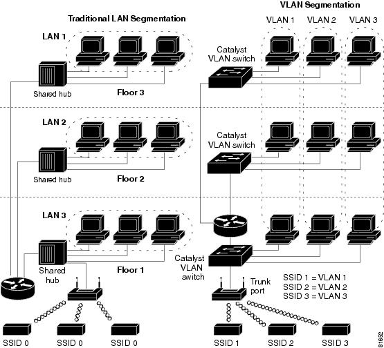
You extend VLANs into a wireless LAN by adding IEEE 802.11Q tag awareness to the access point. Frames destined for different VLANs are transmitted by the access point wirelessly on different SSIDs with different WEP keys. Only the clients associated with that VLAN receive those packets. Conversely, packets coming from a client associated with a certain VLAN are 802.11Q tagged before they are forwarded onto the wired network.
Figure 8-1 shows the difference between traditional physical LAN segmentation and logical VLAN segmentation with wireless devices connected.
Figure 8-1 LAN and VLAN Segmentation with Wireless Devices
Related Documents
These documents provide more detailed information pertaining to VLAN design and configuration:
•![]() Cisco IOS Switching Services Configuration Guide. Click this link to browse to this document:
Cisco IOS Switching Services Configuration Guide. Click this link to browse to this document:
http://www.cisco.com/univercd/cc/td/doc/product/software/ios122/122cgcr/fswtch_c/index.htm
•![]() Cisco Internetwork Design Guide. Click this link to browse to this document:
Cisco Internetwork Design Guide. Click this link to browse to this document:
http://www.cisco.com/univercd/cc/td/doc/cisintwk/idg4/index.htm
•![]() Cisco Internetworking Technology Handbook. Click this link to browse to this document:
Cisco Internetworking Technology Handbook. Click this link to browse to this document:
http://www.cisco.com/univercd/cc/td/doc/cisintwk/ito_doc/index.htm
•![]() Cisco Internetworking Troubleshooting Guide. Click this link to browse to this document:
Cisco Internetworking Troubleshooting Guide. Click this link to browse to this document:
http://www.cisco.com/univercd/cc/td/doc/cisintwk/itg_v1/index.htm
Incorporating Wireless Devices into VLANs
The basic wireless components of a VLAN consist of an access point and a client associated to it using wireless technology. The access point is physically connected through a trunk port to the network VLAN switch on which the VLAN is configured. The physical connection to the VLAN switch is through the access point's Ethernet port.
In fundamental terms, the key to configuring an access point to connect to a specific VLAN is to configure its SSID to recognize that VLAN. Because VLANs are identified by a VLAN ID or name, it follows that if the SSID on an access point is configured to recognize a specific VLAN ID or name, a connection to the VLAN is established. When this connection is made, associated wireless client devices having the same SSID can access the VLAN through the access point. The VLAN processes data to and from the clients the same way that it processes data to and from wired connections. You can configure up to 16 SSIDs on your access point, so you can support up to 16 VLANs. You can assign only one SSID to a VLAN.
You can use the VLAN feature to deploy wireless devices with greater efficiency and flexibility. For example, one access point can now handle the specific requirements of multiple users having widely varied network access and permissions. Without VLAN capability, multiple access points would have to be employed to serve classes of users based on the access and permissions they were assigned.
These are two common strategies for deploying wireless VLANs:
•![]() Segmentation by user groups: You can segment your wireless LAN user community and enforce a different security policy for each user group. For example, you can create three wired and wireless VLANs in an enterprise environment for full-time and part-time employees and also provide guest access.
Segmentation by user groups: You can segment your wireless LAN user community and enforce a different security policy for each user group. For example, you can create three wired and wireless VLANs in an enterprise environment for full-time and part-time employees and also provide guest access.
•![]() Segmentation by device types: You can segment your wireless LAN to allow different devices with different security capabilities to join the network. For example, some wireless users might have handheld devices that support only static WEP, and some wireless users might have more sophisticated devices using dynamic WEP. You can group and isolate these devices into separate VLANs.
Segmentation by device types: You can segment your wireless LAN to allow different devices with different security capabilities to join the network. For example, some wireless users might have handheld devices that support only static WEP, and some wireless users might have more sophisticated devices using dynamic WEP. You can group and isolate these devices into separate VLANs.

Note ![]() You cannot configure multiple VLANs on repeater access points. Repeater access points support only the native VLAN.
You cannot configure multiple VLANs on repeater access points. Repeater access points support only the native VLAN.
Configuring VLANs
These sections describe how to configure VLANs on your access point:
•![]() Using a RADIUS Server to Assign Users to VLANs
Using a RADIUS Server to Assign Users to VLANs
•![]() Viewing VLANs Configured on the Access Point
Viewing VLANs Configured on the Access Point
Configuring a VLAN
Note ![]() When you configure VLANs on access points, the Native VLAN must be VLAN1. In a single architecture, client traffic received by the access point is tunneled through an IP-GRE tunnel, which is established on the access point's Ethernet interface native VLAN. Because of the IP-GRE tunnel, some users may confgure another switch port as VLAN1. This misconfiguration causes errors on the switch port.
When you configure VLANs on access points, the Native VLAN must be VLAN1. In a single architecture, client traffic received by the access point is tunneled through an IP-GRE tunnel, which is established on the access point's Ethernet interface native VLAN. Because of the IP-GRE tunnel, some users may confgure another switch port as VLAN1. This misconfiguration causes errors on the switch port.
Configuring your access point to support VLANs is a three-step process:
1. ![]() Enable the VLAN on the radio and Ethernet ports.
Enable the VLAN on the radio and Ethernet ports.
2. ![]() Assign SSIDs to VLANs.
Assign SSIDs to VLANs.
3. ![]() Assign authentication settings to SSIDs.
Assign authentication settings to SSIDs.
This section describes how to assign SSIDs to VLANs and how to enable a VLAN on the access point radio and Ethernet ports. For detailed instructions on assigning authentication types to SSIDs, see Chapter 6, "Configuring Authentication Types." For instructions on assigning other settings to SSIDs, see Chapter 3, "Configuring Multiple SSIDs."
You can configure up to 16 SSIDs on the access point, so you can support up to 16 VLANs that are configured on your LAN.
Beginning in privileged EXEC mode, follow these steps to assign an SSID to a VLAN and enable the VLAN on the access point radio and Ethernet ports:
|
|
|
|
|---|---|---|
Step 1 |
configure terminal |
Enter global configuration mode. |
Step 2 |
interface dot11radio 0 | 1 |
Enter interface configuration mode for the radio interface. |
Step 3 |
ssid ssid-string |
Create an SSID and enter SSID configuration mode for the new SSID. The SSID can consist of up to 32 alphanumeric characters. SSIDs are case sensitive. Note |
Step 4 |
vlan vlan-id |
(Optional) Assign the SSID to a VLAN on your network. Client devices that associate using the SSID are grouped into this VLAN. Enter a VLAN ID from 1 to 4095. You can assign only one SSID to a VLAN. |
Step 5 |
exit |
Return to interface configuration mode for the radio interface. |
Step 6 |
interface dot11radio 0.x | 1.x |
Enter interface configuration mode for the radio VLAN sub interface. |
Step 7 |
encapsulation dot1q vlan-id [native] |
Enable a VLAN on the radio interface. (Optional) Designate the VLAN as the native VLAN. On many networks, the native VLAN is VLAN 1. |
Step 8 |
exit |
Return to global configuration mode. |
Step 9 |
interface fastEthernet0.x |
Enter interface configuration mode for the Ethernet VLAN subinterface. |
Step 10 |
encapsulation dot1q vlan-id [native] |
Enable a VLAN on the Ethernet interface. (Optional) Designate the VLAN as the native VLAN. On many networks, the native VLAN is VLAN 1. |
Step 11 |
end |
Return to privileged EXEC mode. |
Step 12 |
copy running-config startup-config |
(Optional) Save your entries in the configuration file. |
This example shows how to:
•![]() Name an SSID
Name an SSID
•![]() Assign the SSID to a VLAN
Assign the SSID to a VLAN
•![]() Enable the VLAN on the radio and Ethernet ports as the native VLAN
Enable the VLAN on the radio and Ethernet ports as the native VLAN
router# configure terminal
router(config)# interface dot11radio0
router(config-if)# ssid batman
router(config-ssid)# vlan 1
router(config-ssid)# exit
router(config)# interface dot11radio0.1
router(config-subif)# encapsulation dot1q 1 native
router(config-subif)# exit
router(config)# interface fastEthernet0.1
router(config-subif)# encapsulation dot1q 1 native
router(config-subif)# exit
router(config)# end
Assigning Names to VLANs
You can assign a name to a VLAN in addition to its numerical ID. VLAN names can contain up to 32 ASCII characters. The access point stores each VLAN name and ID pair in a table.
Guidelines for Using VLAN Names
Keep these guidelines in mind when using VLAN names:
•![]() The mapping of a VLAN name to a VLAN ID is local to each access point, so across your network, you can assign the same VLAN name to a different VLAN ID.
The mapping of a VLAN name to a VLAN ID is local to each access point, so across your network, you can assign the same VLAN name to a different VLAN ID.
Note ![]() If clients on your wireless LAN require seamless roaming, Cisco recommends that you assign the same VLAN name to the same VLAN ID across all access points, or that you use only VLAN IDs without names.
If clients on your wireless LAN require seamless roaming, Cisco recommends that you assign the same VLAN name to the same VLAN ID across all access points, or that you use only VLAN IDs without names.
•![]() Every VLAN configured on your access point must have an ID, but VLAN names are optional.
Every VLAN configured on your access point must have an ID, but VLAN names are optional.
•![]() VLAN names can contain up to 32 ASCII characters. However, a VLAN name cannot be a number between 1 and 4095. For example, vlan4095 is a valid VLAN name, but 4095 is not. The access point reserves the numbers 1 through 4095 for VLAN IDs.
VLAN names can contain up to 32 ASCII characters. However, a VLAN name cannot be a number between 1 and 4095. For example, vlan4095 is a valid VLAN name, but 4095 is not. The access point reserves the numbers 1 through 4095 for VLAN IDs.
Creating a VLAN Name
Beginning in privileged EXEC mode, follow these steps to assign a name to a VLAN:
Use the no form of the command to remove the name from the VLAN. Use the show dot11 vlan-name privileged EXEC command to list all the VLAN name and ID pairs configured on the access point.
Using a RADIUS Server to Assign Users to VLANs
You can configure your RADIUS authentication server to assign users or groups of users to a specific VLAN when they authenticate to the network. RADIUS-assigned VLANs are not supported when you enable multiple BSSIDs.
Note ![]() Unicast and multicast cipher suites advertised in WPA information element (and negotiated during 802.11 association) may potentially mismatch with the cipher suite supported in an explicitly assigned VLAN. If the RADIUS server assigns a new vlan ID which uses a different cipher suite from the previously negotiated cipher suite, there is no way for the access point and client to switch back to the new cipher suite. Currently, the WPA protocol does not allow the cipher suite to be changed after the initial 802.11 cipher negotiation phase. In this scenario, the client device is disassociated from the wireless LAN.
Unicast and multicast cipher suites advertised in WPA information element (and negotiated during 802.11 association) may potentially mismatch with the cipher suite supported in an explicitly assigned VLAN. If the RADIUS server assigns a new vlan ID which uses a different cipher suite from the previously negotiated cipher suite, there is no way for the access point and client to switch back to the new cipher suite. Currently, the WPA protocol does not allow the cipher suite to be changed after the initial 802.11 cipher negotiation phase. In this scenario, the client device is disassociated from the wireless LAN.
The VLAN-mapping process consists of these steps:
1. ![]() A client device associates to the access point using any SSID configured on the access point.
A client device associates to the access point using any SSID configured on the access point.
2. ![]() The client begins RADIUS authentication.
The client begins RADIUS authentication.
3. ![]() When the client authenticates successfully, the RADIUS server maps the client to a specific VLAN, regardless of the VLAN mapping defined for the SSID the client is using on the access point. If the server does not return any VLAN attribute for the client, the client is assigned to the VLAN specified by the SSID mapped locally on the access point.
When the client authenticates successfully, the RADIUS server maps the client to a specific VLAN, regardless of the VLAN mapping defined for the SSID the client is using on the access point. If the server does not return any VLAN attribute for the client, the client is assigned to the VLAN specified by the SSID mapped locally on the access point.
These are the RADIUS user attributes used for vlan-id assignment. Each attribute must have a common tag value between 1 and 31 to identify the grouped relationship.
•![]() IETF 64 (Tunnel Type): Set this attribute to VLAN
IETF 64 (Tunnel Type): Set this attribute to VLAN
•![]() IETF 65 (Tunnel Medium Type): Set this attribute to 802
IETF 65 (Tunnel Medium Type): Set this attribute to 802
•![]() IETF 81 (Tunnel Private Group ID): Set this attribute to vlan-id
IETF 81 (Tunnel Private Group ID): Set this attribute to vlan-id
Viewing VLANs Configured on the Access Point
In privileged EXEC mode, use the show vlan command to view the VLANs that the access point supports. This is sample output from a show vlan command:
Virtual LAN ID: 1 (IEEE 802.1Q Encapsulation)
vLAN Trunk Interfaces: Dot11Radio0
FastEthernet0
Virtual-Dot11Radio0
This is configured as native Vlan for the following interface(s) :
Dot11Radio0
FastEthernet0
Virtual-Dot11Radio0
Protocols Configured: Address: Received: Transmitted:
Bridging Bridge Group 1 201688 0
Bridging Bridge Group 1 201688 0
Bridging Bridge Group 1 201688 0
Virtual LAN ID: 2 (IEEE 802.1Q Encapsulation)
vLAN Trunk Interfaces: Dot11Radio0.2
FastEthernet0.2
Virtual-Dot11Radio0.2
Protocols Configured: Address: Received: Transmitted:
VLAN Configuration Example
This example shows how to use VLANs to manage wireless devices on a college campus. In this example, three levels of access are available through VLANs configured on the wired network:
•![]() Management access—Highest level of access; users can access all internal drives and files, departmental databases, top-level financial information, and other sensitive information. Management users are required to authenticate using Cisco LEAP.
Management access—Highest level of access; users can access all internal drives and files, departmental databases, top-level financial information, and other sensitive information. Management users are required to authenticate using Cisco LEAP.
•![]() Faculty access—Medium level of access; users can access school's Intranet and Internet, access internal files, access student databases, and view internal information such as human resources, payroll, and other faculty-related material. Faculty users are required to authenticate using Cisco LEAP.
Faculty access—Medium level of access; users can access school's Intranet and Internet, access internal files, access student databases, and view internal information such as human resources, payroll, and other faculty-related material. Faculty users are required to authenticate using Cisco LEAP.
•![]() Student access—Lowest level of access; users can access school's Intranet and the Internet, obtain class schedules, view grades, make appointments, and perform other student-related activities. Students are allowed to join the network using static WEP.
Student access—Lowest level of access; users can access school's Intranet and the Internet, obtain class schedules, view grades, make appointments, and perform other student-related activities. Students are allowed to join the network using static WEP.
In this scenario, a minimum of three VLAN connections are required, one for each level of access. Because the access point can handle up to 16 SSIDs, you can use the basic design shown in Table 8-1.
|
|
|
|
|---|---|---|
Management |
boss |
1 |
Faculty |
teach |
2 |
Student |
learn |
3 |
Managers configure their wireless client adapters to use SSID boss, faculty members configure their clients to use SSID teach, and students configure their wireless client adapters to use SSID learn. When these clients associate to the access point, they automatically belong to the correct VLAN.
You would complete these steps to support the VLANs in this example:
1. ![]() Configure or confirm the configuration of these VLANs on one of the switches on your LAN.
Configure or confirm the configuration of these VLANs on one of the switches on your LAN.
2. ![]() On the access point, assign an SSID to each VLAN.
On the access point, assign an SSID to each VLAN.
3. ![]() Assign authentication types to each SSID.
Assign authentication types to each SSID.
4. ![]() Configure VLAN 1, the Management VLAN, on both the fastEthernet and dot11radio interfaces on the access point. You should make this VLAN the native VLAN.
Configure VLAN 1, the Management VLAN, on both the fastEthernet and dot11radio interfaces on the access point. You should make this VLAN the native VLAN.
5. ![]() Configure VLANs 2 and 3 on both the fastEthernet and dot11radio interfaces on the access point.
Configure VLANs 2 and 3 on both the fastEthernet and dot11radio interfaces on the access point.
6. ![]() Configure the client devices.
Configure the client devices.
Table 8-2 shows the commands needed to configure the three VLANs in this example.
Table 8-3 shows the results of the configuration commands in Table 8-2. Use the show running command to display the running configuration on the access point.
Notice that when you configure a bridge group on the radio interface, these commands are set automatically:
bridge-group 2
subscriber-loop-control
bridge-group 2
block-unknown-source
no bridge-group 2 source-learning
no bridge-group 2 unicast-flooding
bridge-group 2 spanning-disabled
When you configure a bridge group on the FastEthernet interface, these commands are set automatically:
no bridge-group 2 source-learning
bridge-group 2 spanning-disabled
 Feedback