- Introduction to Cisco 1800 Series Routers (Modular) Hardware Documentation
- Overview of Cisco 1800 Series Routers (Modular)
- Preinstallation Requirements and Planning for Cisco 1800 Series Routers (Modular)
- Chassis Installation Procedures for Cisco 1800 Series Routers (Modular)
- Cable Information and Specifications for Cisco 1800 Series Routers (Modular)
- Cable Connection Procedures for Cisco 1800 Series Routers (Modular)
- Power-Up Procedures for Cisco 1800 Series Routers (Modular)
- Troubleshooting Cisco 1800 Series Routers (Modular)
- Installing Interface Cards in Cisco 1800 Series Routers (Modular)
- Installing and Replacing CompactFlash Memory Cards on Cisco 1800 Series Routers (Modular)
- Installing and Upgrading Internal Modules in Cisco 1800 Series Routers (Modular)
Cisco 1800 Series Hardware Installation (Modular)
Bias-Free Language
The documentation set for this product strives to use bias-free language. For the purposes of this documentation set, bias-free is defined as language that does not imply discrimination based on age, disability, gender, racial identity, ethnic identity, sexual orientation, socioeconomic status, and intersectionality. Exceptions may be present in the documentation due to language that is hardcoded in the user interfaces of the product software, language used based on RFP documentation, or language that is used by a referenced third-party product. Learn more about how Cisco is using Inclusive Language.
- Updated:
- September 30, 2008
Chapter: Power-Up Procedures for Cisco 1800 Series Routers (Modular)
- Powering Up Cisco 1800 Series Routers
- Verifying the LED Indicators on the 1841 Router
- Verifying the LED Indicators on the 1861 Integrated Services Router
- Verifying the Hardware Configuration
- Initial Configuration of the Router
- Powering up the Cisco 1861 Integrated Services Router
- Software Components of the Cisco 1861 Integrated Services Router
Power-Up Procedures for Cisco 1800 Series Routers (Modular)
This chapter describes how to power up Cisco 1800 series integrated services routers (modular) and perform an initial configuration to provide network access. It includes the following sections:
Powering Up Cisco 1800 Series Routers
Verifying the LED Indicators on the 1841 Router
Verifying the Hardware Configuration
Initial Configuration of the Router
Software Components of the Cisco 1861 Integrated Services Router

Note ![]() To see translations of the warnings that appear in this publication, see the Regulatory Compliance and Safety Information for Cisco 1840 Routers.
To see translations of the warnings that appear in this publication, see the Regulatory Compliance and Safety Information for Cisco 1840 Routers.
Note ![]() The Cisco 1861 Integrated Services Router supports a maximum of 12 user licenses based on different models.
The Cisco 1861 Integrated Services Router supports a maximum of 12 user licenses based on different models.
Powering Up Cisco 1800 Series Routers

Warning ![]() The plug-socket combination must be accessible at all times because it serves as the main disconnecting device. Statement 1019
The plug-socket combination must be accessible at all times because it serves as the main disconnecting device. Statement 1019
Warning ![]() Blank faceplates and cover panels serve three important functions: they prevent exposure to hazardous voltages and currents inside the chassis; they contain electromagnetic interference (EMI) that might disrupt other equipment; and they direct the flow of cooling air through the chassis. Do not operate the system unless all cards, faceplates, front covers, and rear covers are in place.
Blank faceplates and cover panels serve three important functions: they prevent exposure to hazardous voltages and currents inside the chassis; they contain electromagnetic interference (EMI) that might disrupt other equipment; and they direct the flow of cooling air through the chassis. Do not operate the system unless all cards, faceplates, front covers, and rear covers are in place.
Statement 1029.

This section covers the following topics:
Checklist for Power Up
You may power up the Cisco router if the following steps have been completed:
•![]() Mount and ground the chassis securely.
Mount and ground the chassis securely.
•![]() Connect the power and interface cables.
Connect the power and interface cables.
•![]() Make sure that the external CompactFlash memory card is properly seated into its slot. For installation instructions, see "Installing and Replacing CompactFlash Memory Cards on Cisco 1800 Series Routers (Modular)".
Make sure that the external CompactFlash memory card is properly seated into its slot. For installation instructions, see "Installing and Replacing CompactFlash Memory Cards on Cisco 1800 Series Routers (Modular)".
•![]() Connect a PC to the router's console port.
Connect a PC to the router's console port.
•![]() Start HyperTerminal or a similar terminal emulation program on your PC. Select the appropriate PC COM port. Set the terminal emulation program configuration for 9600 baud, 8 data bits, 1 stop bit, no flow control, and no parity.
Start HyperTerminal or a similar terminal emulation program on your PC. Select the appropriate PC COM port. Set the terminal emulation program configuration for 9600 baud, 8 data bits, 1 stop bit, no flow control, and no parity.
Note ![]() For initial power up, we recommend a direct console connection. After the intial configuration is completed, a remote modem connection can be used for router management.
For initial power up, we recommend a direct console connection. After the intial configuration is completed, a remote modem connection can be used for router management.
LED Indicators
The meanings of the LED indicators for Cisco 1800 series routers are summarized in Table 2-5. For more detailed information about the LEDs, see Chapter 8, "Troubleshooting Cisco 1800 Series Routers (Modular)."
Power-Up Procedure
To power up your Cisco router and verify that it completes its initialization and self-test, follow this procedure. When you have completed the procedure you may begin configuring the router.
If you encounter problems when you power up the router, see Chapter 8, "Troubleshooting Cisco 1800 Series Routers (Modular)." For information about the ROM monitor and the bootstrap program, see the "Using the ROM Monitor" section of the Cisco 1800 Series Router Software Configuration. For information about the configuration register, see the"Changing the Configuration Register Settings" section of Cisco 1800 Series Router Software Configuration.
Note ![]() To view the boot sequence through a terminal session, you must have a console connection to the Cisco router before the router powers up.
To view the boot sequence through a terminal session, you must have a console connection to the Cisco router before the router powers up.
To power up the router, perform the following steps:
Step 1 ![]() Make sure that your PC is powered up and connected as described in the "Checklist for Power Up" section.
Make sure that your PC is powered up and connected as described in the "Checklist for Power Up" section.
Step 2 ![]() Move the power switch to the ON position.
Move the power switch to the ON position.
The following indications appear:
•![]() The green SYS PWR LED on the front of the chassis comes on.
The green SYS PWR LED on the front of the chassis comes on.
•![]() The fan operates.
The fan operates.
The LEDs on the chassis come on (although not necessarily at the same time), and some LEDs may go off again. The actual LED activity depends on your installation.
If you encounter problems when you power up the router, see "Troubleshooting Cisco 1800 Series Routers (Modular)"
Startup messages appear in your terminal emulation program window.
The startup messages vary, depending on the software installed on your router.
•![]() If the startup messages end with the following lines, you know that the Cisco Router and Security Device Manager (SDM) software is installed on the router.
If the startup messages end with the following lines, you know that the Cisco Router and Security Device Manager (SDM) software is installed on the router.
yourname con0 is now available
Press RETURN to get started!
For instructions on configuring your router by using SDM, see Cisco Router and Security Device Manager (SDM) Quick Start Guide.
Note ![]() Because SDM is installed on your router by default, we recommend using SDM to perform the initial configuration.
Because SDM is installed on your router by default, we recommend using SDM to perform the initial configuration.
•![]() If the startup messages end with the following lines, the router is ready for initial configuration using the setup facility (system configuration dialog) or the command-line interface (CLI). Enter yes to continue with the setup facility; enter no to continue with the CLI.
If the startup messages end with the following lines, the router is ready for initial configuration using the setup facility (system configuration dialog) or the command-line interface (CLI). Enter yes to continue with the setup facility; enter no to continue with the CLI.
.
--- System Configuration Dialog ---
At any point you may enter a question mark '?' for help.
Use ctrl-c to abort configuration dialog at any prompt.
Default settings are in square brackets '[]'.
Would you like to enter the initial configuration dialog? [yes/no]:
Note ![]() If the rommon 1> prompt appears, your system has booted in ROM monitor mode. For information about the ROM monitor and the bootstrap program, see the "Using the ROM Monitor" section in Cisco 1800 Series Router Software Configuration.
If the rommon 1> prompt appears, your system has booted in ROM monitor mode. For information about the ROM monitor and the bootstrap program, see the "Using the ROM Monitor" section in Cisco 1800 Series Router Software Configuration.
Verifying the LED Indicators on the 1841 Router
Verify that you have correctly installed the router by checking the LEDs shown in Table 7-1.
Verifying the LED Indicators on the 1861 Integrated Services Router
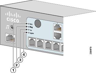
Verify that you have correctly installed the router by checking the LEDs shown in Figure 7-1.
Figure 7-1 LEDs on the Front Panel of the Cisco 1861 Integrated Services Router
|
|
SYS |
Solid green |
Online |
|
|
POE |
Solid green |
Connected |
|
|
VM |
Solid green |
Online |
|
|
WLAN |
Blinking green |
Connected |
Verifying the Hardware Configuration
Verify the router hardware configuration by using the following commands:
•![]() show version—Displays the system hardware version, the installed software version, the names and sources of configuration files, the boot images, and the amount of installed DRAM and flash memory.
show version—Displays the system hardware version, the installed software version, the names and sources of configuration files, the boot images, and the amount of installed DRAM and flash memory.
•![]() show diag—Lists and displays diagnostic information about the installed controllers and interface processors. Typical examples are interface cards (VWICs, WICs, HWICs), and advanced integration modules (AIMs).
show diag—Lists and displays diagnostic information about the installed controllers and interface processors. Typical examples are interface cards (VWICs, WICs, HWICs), and advanced integration modules (AIMs).
Initial Configuration of the Router
This section covers the following topics:
•![]() Verifying the Initial Configuration
Verifying the Initial Configuration
Initial Configuration
You can configure your router by using one of the following tools:
•![]() Cisco Router and Security Device Manager—See the "Cisco Router and Security Device Manager" section
Cisco Router and Security Device Manager—See the "Cisco Router and Security Device Manager" section
•![]() Setup command facility—See the "Initial Configuration Using the Setup Command Facility" section in the Cisco 1800 Series Integrated Services Routers (Modular) Quick Start Guide.
Setup command facility—See the "Initial Configuration Using the Setup Command Facility" section in the Cisco 1800 Series Integrated Services Routers (Modular) Quick Start Guide.
•![]() Command-line interface (CLI)—See the "Initial Configuration Using Cisco CLI—Manual Configuration" section in the Cisco 1800 Series Integrated Services Routers (Modular) Quick Start Guide.
Command-line interface (CLI)—See the "Initial Configuration Using Cisco CLI—Manual Configuration" section in the Cisco 1800 Series Integrated Services Routers (Modular) Quick Start Guide.
Cisco Router and Security Device Manager
If the Cisco Router and Security Device Manager (SDM) has been installed on your router, the following messages appear at the end of the startup sequence:
yourname con0 is now available
Press RETURN to get started.
For instructions on configuring your router by using SDM, see the Cisco Router and Security Device Manager (SDM) Quick Start Guide. To use SDM, you can download the latest version of SDM and instructions for installing it on your router:
http://www.cisco.com/pcgi-bin/tablebuild.pl/sdm
To obtain the SDM quick start guide, SDM release notes, and other SDM documentation, go to www.cisco.com/go/sdm.
Verifying the Initial Configuration
Verify that the new interfaces are operating correctly by performing the following tests:
•![]() Enter the show interfaces command to verify that the interfaces are operating correctly and that the interfaces and line protocol are in the correct state—up or down.
Enter the show interfaces command to verify that the interfaces are operating correctly and that the interfaces and line protocol are in the correct state—up or down.
•![]() Enter the show ip interface brief command to display a summary status of the interfaces configured for IP.
Enter the show ip interface brief command to display a summary status of the interfaces configured for IP.
•![]() Enter the show configuration command to verify that you configured the correct hostname and password.
Enter the show configuration command to verify that you configured the correct hostname and password.
When you have completed and verified the initial configuration, your Cisco router is ready to be configured for specific functions. See the "Completing the Configuration" section for information about locating documentation for advanced configuration procedures.
Completing the Configuration
When you have completed and verified the initial configuration, your Cisco router is ready to be configured for specific functions. For advanced configuration procedures, use either SDM or the CLI.
For configuration procedures using SDM, see Cisco Router and Security Device Manager (SDM) Quick Start Guide.
For configuration procedures using the CLI, see Cisco 1800 Series Router Software Configuration. The software configuration documents include information about the following topics:
•![]() Basic software configuration
Basic software configuration
•![]() Feature documentation
Feature documentation
•![]() Troubleshooting and maintenance
Troubleshooting and maintenance
•![]() Cisco 1800 series cards and modules
Cisco 1800 series cards and modules
Powering up the Cisco 1861 Integrated Services Router
To power up the Cisco 1861 Integrated Services Router, perform the following steps:
Step 1 ![]() Verify that the AC power cord is connected to the power supply.
Verify that the AC power cord is connected to the power supply.
Step 2 ![]() Power up the power supply and the Cisco 1861 ISR, by connecting the power cord plug to a grounded AC outlet.
Power up the power supply and the Cisco 1861 ISR, by connecting the power cord plug to a grounded AC outlet.
Note ![]() There is no external Power On/Off switch on the power supply.
There is no external Power On/Off switch on the power supply.
Step 3 ![]() Verify the LED indicators on the front panel of the Cisco 1861 Integrated Services Router, as required. See Figure 7-1.
Verify the LED indicators on the front panel of the Cisco 1861 Integrated Services Router, as required. See Figure 7-1.
Software Components of the Cisco 1861 Integrated Services Router
The Cisco 1861 Integrated Services Router is shipped with a factory-installed software configuration for a basic IP telephony system that enables phone users to make and receive calls using the preconfigured numbers on their IP phones within minutes after connecting the Cisco 1861 Integrated Services Router to the Ethernet and their IP phones to the platform. Table 7-2 summarizes the software components of the Cisco 1861 Integrated Services Router.
 Feedback