- Introduction to Cisco 1800 Series Routers (Modular) Hardware Documentation
- Overview of Cisco 1800 Series Routers (Modular)
- Preinstallation Requirements and Planning for Cisco 1800 Series Routers (Modular)
- Chassis Installation Procedures for Cisco 1800 Series Routers (Modular)
- Cable Information and Specifications for Cisco 1800 Series Routers (Modular)
- Cable Connection Procedures for Cisco 1800 Series Routers (Modular)
- Power-Up Procedures for Cisco 1800 Series Routers (Modular)
- Troubleshooting Cisco 1800 Series Routers (Modular)
- Installing Interface Cards in Cisco 1800 Series Routers (Modular)
- Installing and Replacing CompactFlash Memory Cards on Cisco 1800 Series Routers (Modular)
- Installing and Upgrading Internal Modules in Cisco 1800 Series Routers (Modular)
Cisco 1800 Series Hardware Installation (Modular)
Bias-Free Language
The documentation set for this product strives to use bias-free language. For the purposes of this documentation set, bias-free is defined as language that does not imply discrimination based on age, disability, gender, racial identity, ethnic identity, sexual orientation, socioeconomic status, and intersectionality. Exceptions may be present in the documentation due to language that is hardcoded in the user interfaces of the product software, language used based on RFP documentation, or language that is used by a referenced third-party product. Learn more about how Cisco is using Inclusive Language.
- Updated:
- March 20, 2015
Chapter: Overview of Cisco 1800 Series Routers (Modular)
Overview of Cisco 1800 Series Routers (Modular)
Cisco 1800 series integrated services routers (ISR) (modular) are modular routers with LAN and WAN connections that can be configured by means of interchangeable interface cards and advanced integration modules (AIMs). The modular design of the routers provides flexibility, allowing you to configure or reconfigure your router according to your needs.
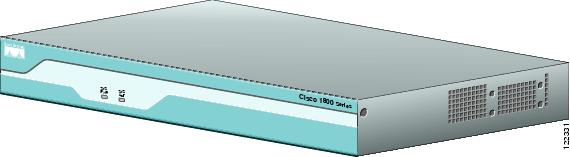
The Cisco 1841 router is a data-only device for desktop use.
Figure 2-1 shows the Cisco 1841 router.
Figure 2-1 The Cisco 1841 Router
The Cisco 1861 ISR, which is part of the Cisco 1800 series ISR family, is a unified communications solution for small- to medium-sized businesses and enterprise small branch offices that provides voice, data, voice-mail, automated attendant, video, and security capabilities while integrating with existing desktop applications such as calendar, e-mail, and customer relationship management (CRM) programs and with built-in security. It has the following core components:
•![]() Integrated Cisco Unified Communications Manager Express or Survivable Remote Site Telephony for call processing for up to 12 users
Integrated Cisco Unified Communications Manager Express or Survivable Remote Site Telephony for call processing for up to 12 users
•![]() Optional Cisco Unity Express for voice messaging and automated attendant
Optional Cisco Unity Express for voice messaging and automated attendant
•![]() Integrated LAN switching with Power over Ethernet (POE) expandable via Cisco Catalyst Switches
Integrated LAN switching with Power over Ethernet (POE) expandable via Cisco Catalyst Switches
•![]() Optional support for a range of WAN interface cards
Optional support for a range of WAN interface cards
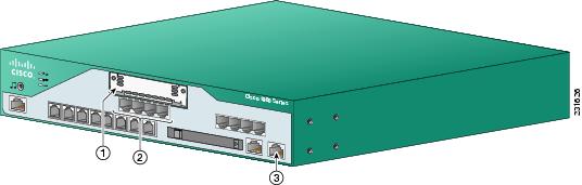
Figure 2-2 and Figure 2-3 show the Cisco 1861 ISR.
Figure 2-2 The Cisco 1861 Integrated Services Router with FXO Ports
|
|
WAN slot |
|
Expansion switch port |
|
|
FXO ports |
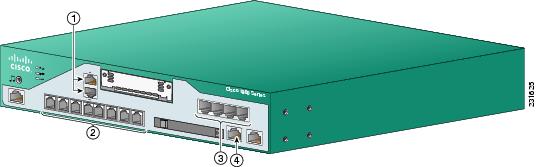
Figure 2-3 The Cisco 1861 Integrated Services Router with BRI Ports
|
|
BRI ports |
|
FXS ports |
|
|
Power over Ethernet (PoE) ports |
|
Fast Ethernet (FE) port |
This chapter describes the features and specifications of the router and includes the following sections:
•![]() Interface Numbering on the 1861 Integrated Services Router
Interface Numbering on the 1861 Integrated Services Router
Hardware Features
This section describes the basic features of Cisco 1800 series routers. It contains the following:
•![]() Product Serial Number Location
Product Serial Number Location
•![]() Removable and Interchangeable Modules
Removable and Interchangeable Modules
Product Serial Number Location
The serial number label for the Cisco 1841 router and the Cisco 1861 ISR is located on the rear of the chassis, underneath interface card slot 0. (See Figure 2-4.)
Figure 2-4 Serial Number Location

Cisco Product Identification Tool
The Cisco Product Identification (CPI) tool provides detailed illustrations and descriptions showing where to locate serial number labels on Cisco products. It includes the following features:
•![]() Search option allows browsing for models using a tree-structured product hierarchy.
Search option allows browsing for models using a tree-structured product hierarchy.
•![]() Search field on the final results page makes it easier to look up multiple products.
Search field on the final results page makes it easier to look up multiple products.
•![]() End-of-sale products are clearly identified in results lists.
End-of-sale products are clearly identified in results lists.
The tool streamlines the process of locating serial number labels and identifying products. Serial number information expedites the entitlement process and is important for access to support services.
The Cisco Product Identification tool can be accessed at the following URL:
http://tools.cisco.com/Support/CPI/index.do
Interfaces
This section summarizes the interfaces available on the Cisco 1800 series routers.
Interfaces on the Cisco 1841 Router
The following interfaces exist on the Cisco 1841 router:
•![]() Two Fast Ethernet ports (RJ-45 connectors)
Two Fast Ethernet ports (RJ-45 connectors)
•![]() High-speed console and auxiliary ports, up to 115.2 kbps each (RJ-45 connectors)
High-speed console and auxiliary ports, up to 115.2 kbps each (RJ-45 connectors)
•![]() One USB port (version 1.1), intended for future use
One USB port (version 1.1), intended for future use
Interfaces on the Cisco 1861 Integrated Services Router
The Cisco 1861 Integrated Services Router comes with various possible configurations, based on built-in ports and other hardware features of the Cisco 1861 Integrated Services Router and organized by model.
Table 2-1 lists the labels and descriptions for the WAN, LAN, voice interface card (VIC), and other interfaces, along with the values for these interfaces in the preconfigured router software configuration.

Note ![]() In Table 2-1, all slots/ports are numbered right to left, unless otherwise noted.
In Table 2-1, all slots/ports are numbered right to left, unless otherwise noted.

* Only one optional VIC can be factory installed in a Cisco 1861 Integrated Services Router.
Removable and Interchangeable Modules
Various optional modules can be installed in the router to provide specific capabilities. These modules can be installed either by inserting them into slots on the chassis, or by opening the chassis and plugging them into connectors inside the chassis.
•![]() Flash memory and interface cards fit into slots on the chassis and can be installed or removed without opening the chassis.
Flash memory and interface cards fit into slots on the chassis and can be installed or removed without opening the chassis.
There are three types of interface cards for the 1800 series modular routers:
–![]() WAN interface cards (WICs)
WAN interface cards (WICs)
–![]() Voice WAN interface cards (VWICs—in data mode only on the Cisco 1841)
Voice WAN interface cards (VWICs—in data mode only on the Cisco 1841)
–![]() High-speed WAN interface cards (HWICs)
High-speed WAN interface cards (HWICs)
•![]() The following components plug into connectors inside the chassis and can be installed or removed only by opening the chassis:
The following components plug into connectors inside the chassis and can be installed or removed only by opening the chassis:
–![]() Advanced integration module (AIM)
Advanced integration module (AIM)
–![]() Synchronous dynamic RAM (SDRAM) small-outline dual in-line memory module (SODIMM)
Synchronous dynamic RAM (SDRAM) small-outline dual in-line memory module (SODIMM)
Table 2-2 summarizes the optional modules:
|
|
|
|
|
|
|---|---|---|---|---|
Cisco 1841 |
1 |
2 single-wide cards |
1 |
1 |
Memory
Cisco 1800 series routers contain the following types of memory:
•![]() SDRAM—Serves two functions. It stores the running configuration and routing tables, and it is used for packet buffering by the network interfaces. Cisco IOS software executes from SDRAM.
SDRAM—Serves two functions. It stores the running configuration and routing tables, and it is used for packet buffering by the network interfaces. Cisco IOS software executes from SDRAM.
•![]() Flash memory—Stores the operating system software image, configuration files, and log files. It is implemented in an external CompactFlash memory card.
Flash memory—Stores the operating system software image, configuration files, and log files. It is implemented in an external CompactFlash memory card.
•![]() Boot/NVRAM—Serves two functions. It stores the ROM monitor, which allows you to boot an operating system software image from flash memory. It also stores the system configuration file and the virtual configuration register.
Boot/NVRAM—Serves two functions. It stores the ROM monitor, which allows you to boot an operating system software image from flash memory. It also stores the system configuration file and the virtual configuration register.
Table 2-3 lists the memory specifications for Cisco 1800 series routers.
|
|
|
|---|---|
SDRAM |
128 MB, expandable to 384 MB; default is 128 MB |
Flash memory |
32, 64, or 128 MB; default is 32MB |
Boot/NVRAM |
2/4 MB flash memory |
Note ![]() SDRAM and the flash memory are user-upgradable, but the boot/NVRAM is permanently soldered to the router's motherboard and is not upgradable.
SDRAM and the flash memory are user-upgradable, but the boot/NVRAM is permanently soldered to the router's motherboard and is not upgradable.
|
|
|
|---|---|
DRAM |
512 MB |
Flash memory |
128 MB |
LED Indicators
Table 2-5 summarizes the LED indicators for the Cisco 1841 router that are located in the router bezel or chassis, but not in the interface cards.
For descriptions of the LEDs in the interface cards, see Cisco Interface Card Installation Guide.
|
|
|
|
|
|---|---|---|---|
SYS PWR |
Green |
Router has successfully booted and the software is functional. |
Front |
SYS ACT |
Green |
Blinking when any packets are transmitted or received on any |
Front |
CF |
Green |
On when flash memory is busy. Do not remove the CompactFlash |
Back |
FDX (FE 0/0) |
Green |
On indicates full-duplex operation. Off indicates half-duplex |
Back |
100 (FE 0/0) |
Green |
On indicates a 100-Mbps link. Off indicates a 10-Mbps link. |
Back |
Link (FE 0/0) |
Green |
On when the router is correctly connected to a local Ethernet |
Back |
FDX (FE 0/1) |
Green |
On indicates full-duplex operation. Off indicates half-duplex |
Back |
100 (FE 0/1) |
Green |
On indicates a 100-Mbps link. Off indicates a 10-Mbps link. |
Back |
Link (FE 0/1) |
Green |
On when the router is correctly connected to a local Ethernet |
Back |
AIM |
Green |
On indicates presence of an AIM in the internal AIM slot. |
Back |
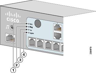
Figure 2-5 summarizes the LED indicators for the Cisco 1861 ISR that are located in the router bezel.
Figure 2-5 LEDs on the Front Panel of the Cisco 1861 Integrated Services Router
|
|
SYS |
Solid green |
Online |
|
|
POE |
Solid green |
Connected |
|
|
VM |
Solid green |
Online |
|
|
WLAN |
Blinking green |
Connected |
Chassis Ventilation
An internal three-speed fan provides chassis cooling. An onboard temperature sensor controls the fan speed. The fan is always on when power is applied to the router. Under most conditions, the fan operates at the slowest speed to conserve power and reduce fan noise. It operates at the higher speeds when necessary under conditions of higher ambient temperature.
Real-Time Clock
An internal real-time clock with battery backup provides the system software with time of day on system power up. This allows the system to verify the validity of a certification authority (CA) certificate. The backup battery is a socketed lithium battery. This battery lasts the life of the router under the operating environmental conditions specified for the router, and is not field replaceable.
Note ![]() If the lithium battery in a Cisco 1841 router should fail, the router must be returned to Cisco for repair. Do not replace the battery yourself. Although the battery is not intended to be field replaceable, the safety agencies require the following warning be included in this document.
If the lithium battery in a Cisco 1841 router should fail, the router must be returned to Cisco for repair. Do not replace the battery yourself. Although the battery is not intended to be field replaceable, the safety agencies require the following warning be included in this document.

Warning ![]() There is the danger of explosion if the battery is replaced incorrectly. Replace the battery only with the same or equivalent type recommended by the manufacturer. Dispose of used batteries according to the manufacturer's instructions. Statement 1015
There is the danger of explosion if the battery is replaced incorrectly. Replace the battery only with the same or equivalent type recommended by the manufacturer. Dispose of used batteries according to the manufacturer's instructions. Statement 1015
Chassis Security
The chassis of the Cisco 1841 router is constructed with a KensingtonTM security slot on the back panel. It can be secured to a desktop or other surface by using KensingtonTM lockdown equipment.
Chassis Views
This section contains views of the front and rear panels of Cisco 1841 router, showing the locations of the power and signal interfaces, the interface card slots, and the status indicators.
Figure 2-6 shows the front panel of a Cisco 1841 router. Figure 2-7 shows the back panel.
Figure 2-6 Front Panel of the Cisco 1841 Router
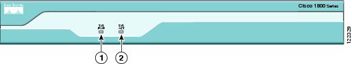
|
|
System Power (SYS PWR) LED |
|
System Activity (SYS ACT) LED |
Figure 2-7 Back Panel of the Cisco 1841 Router
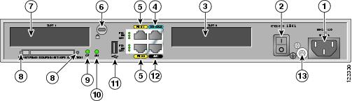
|
|
Input power connection |
|
CompactFlash memory card slot |
|
|
On/Off switch |
|
CompactFlash (CF) LED |
|
|
Slot 0 (WIC, VWIC—data only, or HWIC) |
|
AIM LED |
|
|
Console port |
|
USB port |
|
|
Fast Ethernet ports and LEDs |
|
Aux port |
|
|
KensingtonTM security slot |
|
Chassis ground connection |
|
|
Slot 1 (WIC, VWIC—data only, or HWIC) |
Interface Numbering
Each individual interface (port) on a Cisco 1841 router is identified by a number. A Cisco 1841 router contains the following wide-area network (WAN) and local-area network (LAN) interface types:
•![]() Two onboard Fast Ethernet LAN interfaces
Two onboard Fast Ethernet LAN interfaces
•![]() Two slots in which you can install WICs, VWICs (data only), and HWICs.
Two slots in which you can install WICs, VWICs (data only), and HWICs.
The numbering format for the slots is interface-type 0/slot-number/interface-number. Table 2-6 summarizes the interface numbering.
|
|
|
|
|
|---|---|---|---|
Onboard Ports |
Fast Ethernet |
0/0 and 0/1 |
interface fastethernet 0/0 |
Slot 0 |
HWIC/WIC/VWIC2 |
0/0/0 to 0/0/3 |
interface serial 0/0/0 line async 0/0/0 |
Slot 1 |
HWIC/WIC/VWIC2 |
0/1/0 to 0/1/3 |
interface serial 0/1/0 line async 0/1/0 |
1 The interfaces listed are examples only; other possible interface types are not listed. 2 VWICs are data-only in a Cisco 1841 router. |
Note ![]() On the Cisco 1841 router, the numbering format for configuring an async interface is 0/slot/port. To configure the line associated with an async interface, simply use the interface number to specify the async line. For example, line 0/0/0 specifies the line associated with interface serial 0/0/0 on a WIC-2A/S in slot 0. Similarly, line 0/1/1 specifies the line associated with interface async 0/1/1 on a WIC-2AM in slot 1.
On the Cisco 1841 router, the numbering format for configuring an async interface is 0/slot/port. To configure the line associated with an async interface, simply use the interface number to specify the async line. For example, line 0/0/0 specifies the line associated with interface serial 0/0/0 on a WIC-2A/S in slot 0. Similarly, line 0/1/1 specifies the line associated with interface async 0/1/1 on a WIC-2AM in slot 1.
Interface Numbering on the 1861 Integrated Services Router
Each interface (port) on a Cisco 1861 ISR is identified by a number. The Cisco 1861 router contains the following WANLAN interface types:
•![]() One onboard Fast Ethernet LAN interface (FastEthernet0/0)
One onboard Fast Ethernet LAN interface (FastEthernet0/0)
•![]() One onboard Ethernet switch
One onboard Ethernet switch
•![]() One fixed VIC slot with 4 FXS ports
One fixed VIC slot with 4 FXS ports
•![]() One fixed VIC slot with 4 FXO or 2 BRI ports
One fixed VIC slot with 4 FXO or 2 BRI ports
•![]() One modular HWIC/WIC/VWIC slot
One modular HWIC/WIC/VWIC slot
The numbering format for the slots is interface-type 0/slot-number/port-number. Table 2-7 summarizes the interface numbering.
|
|
|
|
|
|---|---|---|---|
Onboard Ports |
Fast Ethernet |
0/0 |
interface fastethernet 0/0 |
Onboad Slot 1 |
Fast Ethernet Switch |
0/1/0 to 0/1/7 |
interface fastethernet 0/1/0 |
Fixed HWIC slot 0 |
FXS |
0/0/0 to 0/0/3 |
voice-port 0/0/0/ |
Fixed HWIC slot 1 |
FXO |
0/1/0 to 0/1/3 |
voice-port 0/1/0 |
BRI |
0/1/0 to 0/1/1 |
||
Modular HWIC Slot |
HWIC/WIC/VWIC |
0/3/0 to 0/3/x, where x depends on the card-type. |
interface serial 0/0/0 |
1 The interfaces listed are examples only; other possible interface types are not listed. |
Note ![]() On the Cisco 1861 ISR, the numbering format for configuring an asynchronous, or async, interface is 0/slot/port. To configure the line associated with an async interface, simply use the interface number to specify the async line. For example, line 0/0/0 specifies the line associated with interface serial 0/0/0 on a WIC-2A/S in slot 0. Similarly, line 0/1/1 specifies the line associated with interface async 0/1/1 on a WIC-2AM in slot 1.
On the Cisco 1861 ISR, the numbering format for configuring an asynchronous, or async, interface is 0/slot/port. To configure the line associated with an async interface, simply use the interface number to specify the async line. For example, line 0/0/0 specifies the line associated with interface serial 0/0/0 on a WIC-2A/S in slot 0. Similarly, line 0/1/1 specifies the line associated with interface async 0/1/1 on a WIC-2AM in slot 1.
Note ![]() If you have specified the use of a private line automatic ringdown (PLAR) off-premises extension (OPX) connection mode for an FXO voice port (with loop resistance less than 8000 Ohm), you must ensure that the soft-offhook option is enabled on the port.
If you have specified the use of a private line automatic ringdown (PLAR) off-premises extension (OPX) connection mode for an FXO voice port (with loop resistance less than 8000 Ohm), you must ensure that the soft-offhook option is enabled on the port.
This option allows a stepped offhook resistance during seizure, which avoids overloading the circuit during offhook in the event that ringing voltage is present on the circuit at the same time as the trunk seizure. The stepped offhook resistance is initially set to 800 Ohms, then adjusts to 50 Ohms when ringing voltage is not present.
To enable the soft-offhook command on the port, and to access the connection command with plar opx syntax, see Cisco Command Lookup Tool.
Specifications
Table 2-8 lists the specifications for Cisco 1800 series routers.
|
|
|
|---|---|
Dimensions without rubber feet |
1.73 x 13.5 x 10.8 in. (4.4 x 34.3 x 27.4 cm) |
Weight (no modules installed) |
6.1 lb. (2.77 kg) |
Input voltage, AC power supply |
100 to 240 VAC, autoranging |
Power consumption |
20 W maximum for an unloaded unit. |
Console and auxiliary ports |
RJ-45 connectors |
Operating humidity |
5 to 95%, noncondensing |
Operating temperature |
32 to 104°F (0 to 40°C) |
Nonoperating temperature shock |
-13 to 158°F (-25 to 70°C) at 9° F (5° C)/minute minimum |
Noise level |
Normal operating temperature (< 78° F or 26° C): 34 dBa |
Regulatory compliance |
For detailed regulatory compliance information, see |
Electromagnetic compatibility |
FCC Part 15 Class A. |
Safety compliance |
UL 60950; CSA 60950; IEC 60950; EN 60950; AS/NZS 3260; NOM-019-SCFI-1998. |
Regulatory Compliance
For compliance information, see Regulatory Compliance and Safety Information for Cisco 1840 Routers document that accompanies the router.
 Feedback