- Introduction to Cisco 1800 Series Routers (Modular) Hardware Documentation
- Overview of Cisco 1800 Series Routers (Modular)
- Preinstallation Requirements and Planning for Cisco 1800 Series Routers (Modular)
- Chassis Installation Procedures for Cisco 1800 Series Routers (Modular)
- Cable Information and Specifications for Cisco 1800 Series Routers (Modular)
- Cable Connection Procedures for Cisco 1800 Series Routers (Modular)
- Power-Up Procedures for Cisco 1800 Series Routers (Modular)
- Troubleshooting Cisco 1800 Series Routers (Modular)
- Installing Interface Cards in Cisco 1800 Series Routers (Modular)
- Installing and Replacing CompactFlash Memory Cards on Cisco 1800 Series Routers (Modular)
- Installing and Upgrading Internal Modules in Cisco 1800 Series Routers (Modular)
Cisco 1800 Series Hardware Installation (Modular)
Bias-Free Language
The documentation set for this product strives to use bias-free language. For the purposes of this documentation set, bias-free is defined as language that does not imply discrimination based on age, disability, gender, racial identity, ethnic identity, sexual orientation, socioeconomic status, and intersectionality. Exceptions may be present in the documentation due to language that is hardcoded in the user interfaces of the product software, language used based on RFP documentation, or language that is used by a referenced third-party product. Learn more about how Cisco is using Inclusive Language.
- Updated:
- September 30, 2008
Chapter: Installing Interface Cards in Cisco 1800 Series Routers (Modular)
Installing Interface Cards in Cisco 1800 Series Routers (Modular)
Cisco Interface Cards Installation Guide
The Cisco Interface Cards Installation Guide contains the procedures for installing the various types of interface cards in external chassis slots. Interface cards supported by the Cisco 1800 series integrated services routers (modular) include the following types:
•![]() Voice-WAN interface cards (VWICs)—data only on the Cisco 1841 router
Voice-WAN interface cards (VWICs)—data only on the Cisco 1841 router
•![]() WAN interface cards (WICs)
WAN interface cards (WICs)
•![]() High-speed WAN interface cards (HWICs)
High-speed WAN interface cards (HWICs)
You can view the Cisco Interface Cards Installation Guide on Cisco.com.
Related Product Documentation
The following documentation is related to your product. This document was not shipped with your product, but you can access it on Cisco.com.
•![]() Cisco Network Modules and Interface Cards Regulatory Compliance and Safety Information
Cisco Network Modules and Interface Cards Regulatory Compliance and Safety Information
Installing WICs, VWICs, and HWICs
This section describes how to install WICs, VWICs, and HWICs into Cisco 1800 series routers.

The Cisco 1841 router has two interface card slots. Each slot can accommodate a Cisco WIC, VWIC (data only mode), or a single-wide high-speed WIC (HWIC).

Note ![]() Cisco double-wide HWICs are not supported in the Cisco 1841 router.
Cisco double-wide HWICs are not supported in the Cisco 1841 router.
To install a card in a Cisco 1841 router, follow these steps:
Step 1 ![]() Make sure that the router is turned off and is disconnected from power.
Make sure that the router is turned off and is disconnected from power.
Step 2 ![]() Loosen the thumbscrews on the interface card blank faceplate on the back panel, as shown in Figure 9-1. You should be able to loosen the screws using your fingers; however, if the screws are very tight, you might need to use a Phillips screwdriver.
Loosen the thumbscrews on the interface card blank faceplate on the back panel, as shown in Figure 9-1. You should be able to loosen the screws using your fingers; however, if the screws are very tight, you might need to use a Phillips screwdriver.
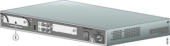
Figure 9-1 Removing an Interface Card Blank Faceplate
|
|
Blank faceplate |
Step 3 ![]() Remove the blank faceplate that covers the card slot.
Remove the blank faceplate that covers the card slot.
Step 4 ![]() Hold the interface card by the edges on either side of the card front panel, and line up the card edges with the guides inside the card slot, as shown in Figure 9-2.
Hold the interface card by the edges on either side of the card front panel, and line up the card edges with the guides inside the card slot, as shown in Figure 9-2.
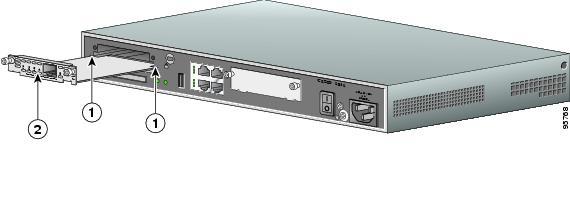
Figure 9-2 Inserting an Interface Card into the Router
|
|
Card guides |
|
Interface card |
Step 5 ![]() Insert the card in the slot, and gently push it into the router until the front panel of the card is flush with the back panel of the router.
Insert the card in the slot, and gently push it into the router until the front panel of the card is flush with the back panel of the router.
Step 6 ![]() Tighten the screws.
Tighten the screws.
 Feedback