- Title
- Contents
- Preface
- part 1
- Basic Router Configuration
- part 2
- Sample Network Deployments
- Configuring PPP over Ethernet with NAT
- Configuring PPP over ATM with NAT
- Configuring a LAN with DHCP and VLANs
- Configuring a VPN Using Easy VPN and an IPSec Tunnel
- Configuring VPNs Using an IPSec Tunnel and Generic Routing Encapsulation
- Configuring a Simple Firewall
- Configuring a Wireless LAN Connection
- Sample Configuration
- Additional Configuration Options
- part 3
- Configuring Security Features
- Configuring Dial Backup and Remote Management
- Troubleshooting
- part 4
- Cisco IOS Software Basic Skills
- Concepts
- ROM Monitor
- Common Port Assignments
- Index
Cisco 1800 Series Integrated Services Routers (Fixed) Software Configuration Guide
Bias-Free Language
The documentation set for this product strives to use bias-free language. For the purposes of this documentation set, bias-free is defined as language that does not imply discrimination based on age, disability, gender, racial identity, ethnic identity, sexual orientation, socioeconomic status, and intersectionality. Exceptions may be present in the documentation due to language that is hardcoded in the user interfaces of the product software, language used based on RFP documentation, or language that is used by a referenced third-party product. Learn more about how Cisco is using Inclusive Language.
Chapter: Configuring PPP over ATM with NAT
Configuring PPP over ATM with NAT
The Cisco 1801, Cisco 1802, and Cisco 1803 access routers support Point-to-Point Protocol over Asynchronous Transfer Mode (PPPoA) clients and network address translation (NAT).
Multiple PCs can be connected to the LAN behind the router. Before traffic from the PCs is sent to the PPPoA session, it can be encrypted, filtered, and so forth. PPP over ATM provides a network solution with simplified address handling and straight user verification like a dial network. Figure 4-1 shows a typical deployment scenario with a PPPoA client and NAT configured on the Cisco router. This scenario uses a single static IP address for the ATM connection.
Figure 4-1 PPP over ATM with NAT
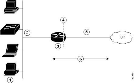
In this scenario, the small business or remote user on the Fast Ethernet LAN can connect to an Internet Service Provider (ISP) using the following protocols on the WAN connection:
- Asymmetric digital subscriber line (ADSL) over plain old telephone service (POTS) using the Cisco 1801 router
- ADSL over integrated services digital network (ISDN) using the Cisco 1802 router
- Single-pair high-speed digital subscriber line (G.SHDSL) using the Cisco 1803 router
The Fast Ethernet interface carries the data packet through the LAN and off-loads it to the PPP connection on the ATM interface. The ATM traffic is encapsulated and sent over the ADSL, ISDN, or G.SHDSL lines. The dialer interface is used to connect to the ISP.
The PPPoA Client feature on the router provides PPPoA client support on ATM interfaces. A dialer interface must be used for cloning virtual access. Multiple PPPoA client sessions can be configured on an ATM interface, but each session must use a separate dialer interface and a separate dialer pool.
A PPPoA session is initiated on the client side by the Cisco 1800 series router.
NAT (represented as the dashed line at the edge of the Cisco router) signifies two addressing domains and the inside source address. The source list defines how the packet travels through the network.
Perform the following tasks to configure this network scenario:
- Configure the Dialer Interface
- Configure the ATM WAN Interface
- Configure DSL Signaling Protocol
- Configure Network Address Translation
An example showing the results of these configuration tasks is shown in the section “Configuration Example.”
Configure the Dialer Interface
The dialer interface indicates how to handle traffic from the clients, including, for example, default routing information, the encapsulation protocol, and the dialer pool to use. It is also used for cloning virtual access. Multiple PPPoA client sessions can be configured on an ATM interface, but each session must use a separate dialer interface and a separate dialer pool.
Perform these steps to configure a dialer interface for the ATM interface on the router, starting in global configuration mode.
Creates a dialer interface (numbered 0–255), and enters into interface configuration mode. |
||
Specifies that the IP address for the dialer interface is obtained through PPP/IPCP (IP Control Protocol) address negotiation. |
||
Sets the size of the IP maximum transmission unit (MTU). The default minimum is 128 bytes. The maximum for ATM is 4470 bytes. |
||
Sets the encapsulation type to PPP for the data packets being transmitted and received. |
||
Sets the PPP authentication method. The example applies the Challenge Handshake Authentication Protocol (CHAP). For details about this command and additional parameters that can be set, see the Cisco IOS Security Command Reference . |
||
Specifies the dialer pool to use to connect to a specific destination subnetwork. |
||
Assigns the dialer interface to a dialer group (1–10). Tip Using a dialer group controls access to your router. |
||
dialer-list dialer-group protocol protocol-name {permit | deny | list access-list-number | access-group} |
Creates a dialer list and associates a dial group with it. Packets are then forwarded through the specified interface dialer group. For details about this command and additional parameters that can be set, see the Cisco IOS Dial Technologies Command Reference . |
|
Sets the IP route for the default gateway for the dialer 0 interface. For details about this command and additional parameters that can be set, see the Cisco IOS IP Command Reference, Volume 1 of 4: Routing Protocols . |
Repeat these steps for any additional dialer interfaces or dialer pools needed.
Configure the ATM WAN Interface
Perform these steps to configure the ATM interface, beginning in global configuration mode.
Enters interface configuration mode for the ATM interface (labeled ADSLoPOTS or G.SHDSL on the back of your router). Note This interface was initially configured during basic router configuration. See “Configure WAN Interfaces” section. |
||
Creates an ATM PVC for each end node (up to ten) with which the router communicates. Enters ATM virtual circuit configuration mode. When a PVC is defined, AAL5SNAP encapsulation is defined by default. Use the encapsulation command to change this, as shown in . The VPI and VCI arguments cannot be simultaneously specified as zero; if one is 0, the other cannot be 0. For details about this command and additional parameters that can be set, see the Cisco IOS Wide-Area Networking Command Reference . |
||
encapsulation { aal5auto | aal5autoppp virtual-template number [ group group-name ] | aal5ciscoppp virtual-template number | aal5mux protocol | aal5nlpid | aal5snap } |
Specifies the encapsulation type for the PVC and points back to the dialer interface. For details about this command and additional parameters that can be set, see the Cisco IOS Wide-Area Networking Command Reference . |
|
Specifies the ATM interface as a member of a dialer profile dialing pool. The pool number must be in the range of 1–255. |
||
Enables interface and configuration changes just made to the ATM interface. |
||
Configure DSL Signaling Protocol
DSL signaling must be configured on the ATM interface for connection to your ISP. The Cisco 1801 supports ADSL signaling over POTS, the Cisco 1802 supports ADSL signaling over ISDN, and the Cisco 1803 supports SHDSL signaling.
Based on the router you are configuring, see one of the following sections to configure the appropriate DSL signaling protocol.
Configuring ADSL
The default configuration for ADSL signaling is shown in Table 4-1 .
Specifies the operating mode of the digital subscriber line (DSL) for an ATM interface. |
||
Toggles between enabling the training log and disabling the training log. |
If you wish to change any of these settings, use one of the following commands in global configuration mode.
- dsl operating-mode (from the ATM interface configuration mode)
- dsl lom integer
- dsl enable-training-log
See the Cisco IOS Wide-Area Networking Command Reference for details of these commands.
Verify the Configuration
You can verify that the configuration is set the way you want using the show dsl interface atm 0 command from privileged EXEC mode.
Configuring SHDSL
Complete the following steps to configure the DSL controller in your router to use SHDSL signaling, beginning in global configuration mode.

Note If you are integrating your Cisco router into a European network, please use one of the following commands:
For CO mode, use the dsl dsl-mode shdsl symmetric annex {A | B | B-ANFP} command to choose annex B or B-ANFP.
For CPE mode, use the dsl dsl-mode shdsl symmetric annex {A | A-B | A-B-ANFP | B | B-ANFP} to choose any option except option A.
The router uses annex A by default (United States).
Configure Network Address Translation
Network Address Translation (NAT) translates packets from addresses that match a standard access list, using global addresses allocated by the dialer interface. Packets that enter the router through the inside interface, packets sourced from the router, or both are checked against the access list for possible address translation. You can configure NAT for either static or dynamic address translations.
Perform these steps to configure the outside ATM WAN interface with dynamic NAT, beginning in global configuration mode:
ip nat pool name start-ip end-ip { netmask netmask | prefix-length prefix-length } |
||
ip nat inside source {list access-list-number } {interface type number | pool name } [overload] |
Enables dynamic translation of addresses on the inside interface. The first example shows the addresses permitted by the access list 1 to be translated to one of the addresses specified in the dialer interface 0 . The second example shows the addresses permitted by access list acl1 to be translated to one of the addresses specified in the NAT pool pool1 . For details about this command and additional parameters that can be set, as well as information about enabling static translation, see the Cisco IOS IP Command Reference, Volume 1 of 4: Addressing and Services . |
|
Enters configuration mode for the VLAN (on which the Fast Ethernet LAN interfaces [FE2–FE9] reside) to be the inside interface for NAT. |
||
Applies NAT to the Fast Ethernet LAN interface as the inside interface. For details about this command and additional parameters that can be set, as well as information about enabling static translation, see the Cisco IOS IP Command Reference, Volume 1 of 4: Addressing and Services . |
||
Enables the configuration changes just made to the Ethernet interface. |
||
Enters configuration mode for the ATM WAN interface (FE0 or FE1) to be the outside interface for NAT. |
||
Identifies the specified WAN interface as the NAT outside interface. For details about this command and additional parameters that can be set, as well as enabling static translation, see the Cisco IOS IP Command Reference, Volume 1 of 4: Addressing and Services . |
||
Enables the configuration changes just made to the Ethernet interface. |
||
access-list access-list-number { deny | permit} source [ source-wildcard ] |
Defines a standard access list permitting addresses that need translation. Note All other addresses are implicitly denied. |
Note If you want to use NAT with a virtual-template interface, you must configure a loopback interface. See “Basic Router Configuration,” for information on configuring the loopback interface.
For complete information on NAT commands, see the Cisco IOS Release 12.3 documentation set. For more general information on NAT concepts, see Appendix B, “Concepts.”
Configuration Example
The following configuration example shows a portion of the configuration file for a client in the PPPoA scenario described in this chapter.
The VLAN interface has an IP address of 192.168.1.1 with a subnet mask of 255.255.255.0. NAT is configured for inside and outside.
Note Commands marked by “(default)” are generated automatically when you run the show running-config command.
 Feedback