Introduction
The Cisco Catalyst IR1101 Rugged Series Router is a next generation modular industrial router which has a base module with additional Pluggable Modules that can be added. The Pluggable Module provides the flexibility of adding different interfaces to the IR1101 platform, for example, a cellular module.
The IR1101 also has an Expansion Module that adds key capabilities to the IR1101, such as mSATA SSD FRU, Ethernet SFP port, and Digital GPIO connections. It also makes the IR1101 dual LTE capable, with one module in the base and the other in the expansion module.
 Note |
The documentation set for this product strives to use bias-free language. For purposes of this documentation set, bias-free is defined as language that does not imply discrimination based on age, disability, gender, racial identity, ethnic identity, sexual orientation, socioeconomic status, and intersectionality. Exceptions may be present in the documentation due to language that is hardcoded in the user interfaces of the product software, language used based on RFP documentation, or language that is used by a referenced third-party product. |
Note |
The IR-1100-SP Expansion Module is the same as the IR-1100-SPMI module, without the Digital I/O and mSATA components. |
Interface Naming Conventions
| Port |
Naming Convention |
|---|---|
|
Gigabit Ethernet combo port |
Gigabitethernet 0/0/0 |
|
Gigabit Ethernet SFP port on Expansion Module |
Gigabitethernet 0/0/5 |
|
Fast Ethernet ports |
Fastethernet 0/0/1-0/0/4 |
|
Cellular Interface on IR1101 Base |
Cellular 0/1/0 and Cellular 0/1/1 |
|
Cellular Interface on Expansion Module |
Cellular 0/3/0 and Cellular 0/3/1 |
|
Asynchronous Serial Interface |
Async 0/2/0 |
|
USB |
usbflash0: |
|
mSATA |
msata |
|
IR1101 Base Unit Alarm input |
alarm contact 0 |
|
GPIO on Expansion Module |
alarm contact 1-4 |
Software Images for IoT Routers
Note |
You must have a Cisco.com account to download the software. |
Cisco IOS-XE Release 17.5.1 includes the following Cisco images:
|
Router |
Image Type |
Filename |
|---|---|---|
|
IR1101 |
Universal |
ir1101-universalk9.17.05.01.SPA.bin |
|
NPE |
ir1101-universal9_npe.17.05.01.SPA.bin |
The latest software downloads for the Routers can be found at:
https://software.cisco.com/download/home/286319772/type
Click on the IR1101 link to take you to the specific software you are looking for.
New Features in Cisco IOS XE 17.5.1
These are the new features for the IR1101.
DSL SFP Annex J Support
IOS-XE release 17.5.1 adds in support for Annex-J configuration in the controller interface.
Note |
ADSL2+ J is supported, ADSL2 J is not yet supported in 17.5.1. |
To enable Annex-J, perform the following:
router#config term
router(conf)#controller vdsl 0/0/0
router(conf-if)#capability annex-j
router#(conf-if)#exit
router#
To remove Annex-J, perform the following:
router#config term
router(conf)#controller vdsl 0/0/0
router(conf-if)#no capability annex-j
router#(conf-if)#exit
router#
17.5.1 adds in a new command rx-padding. This command is used for packets with an MTU less than 64 bytes.
Important |
If frames less than 64mtu are expected downstream from the service provider, the Vlan configuration must be vlan 96. |
The command example is as follows:
router#config term
router#controller vdsl 0/0/0
router(conf-if)#rx-padding
router(conf-if)#end
Execute write mem to save the configuration.
VXLAN
VXLAN is a MAC in IP/UDP (MAC-in-UDP) encapsulation technique with a 24-bit segment identifier in the form of a VXLAN ID. The larger VXLAN ID allows LAN segments to scale to 16 million in a cloud network. In addition, the IP/UDP encapsulation allows each LAN segment to be extended across existing Layer 3 networks, making use of Layer 3 Equal-Cost Multi-Path (ECMP).
Note |
VXLAN requires Network Advantage licensing. |
The following shows an example configuration for enabling VXLAN. With this configuration, Client A and Client B are on the same broadcast domain.
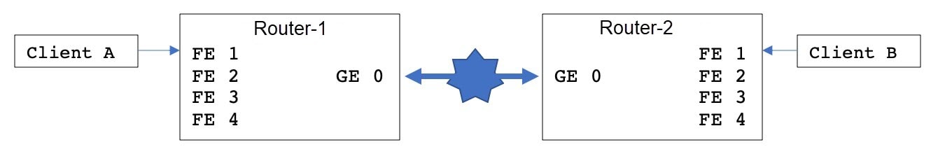
The configuration for the two devices is shown in the following table:
|
Router-1 |
Router-2 |
|---|---|
|
|
Dying-Gasp SMS Notification for EM74XX Modems
Prerequisites:
-
Hardware Peripheral: P-LTEA-EA, P-LTEA-LA
-
Initial Release: IOS-XE 17.5.1
-
License: Cisco Network-advantage
Pluggable Interface Modules (PIMs) using the EM7430 or EM7455 modem have extra capacitors to supply power to the modem in case of loss of power to the module. This allows a graceful power off of the modem. When loss of power is detected, the modem is expected to send out dying gasp SMS when configured.
The following is an example of configuring dying gasp with a phone number and SMS message:
#controller Cellular 0/1/0
#lte dyinggasp detach enable
#lte dyinggasp sms send 4085551212 IR1101-EM7455_going_down_now!
#lte sms archive path tftp://10.10.10.10/
Warning: Enabling Dying Gasp SMS configuration completed successfully.
Please reset Modem for the changes to take effect
SNMP MIB for Digital I/O
Digital I/O is similar to the ALARM IN and ALARM OUT supported in other IR devices. On other devices, ALARM IN is a dedicated input and the ALARM OUT is a dedicated output. With Digital I/O it can be input or output. There are 4 Digital I/O available on the IR1101 with an Expansion Module.
MIB support will reflect the show alarm output for digital I/O only.
CISCO-DIGITAL-IO-MIB.my will have 4 digital I/O nodes. Each digital I/O node will have corresponding attributes like description, enable, severity, application, output, threshold, trigger leaf nodes for each digital I/O nodes.
GPS access to IOx Apps
Previously, when a modem has GPS enabled, the NMEA stream was not forwarded to IOx. This release allows the NMEA stream to be forwarded to IOx from the ngiolite module. There are two steps to enable this.
-
Create a tunnel between Linux and IOx
-
Forward all NMEA messages over the tunnel to IOx.
The system code checks for the presence of the tunnel, and if it is not present, data cannot be sent to IOx.
To support this feature there will be two new tunnels created for two cellular modems on the IR1101 and IR1800. Two tunnels are created by default and whichever modem has the GPS/NMEA enabled, the NMEA stream will be sent over the corresponding tunnel as follows:
Modem0:
[Linux] /dev/ttyTun5 and /dev/ttyTun6 [IOx]. Soft link to /dev/ttyTun5 will be created named /dev/ttyTunNMEA0, soft link to /dev/ttyTun6 will be created named /dev/ttyNMEA0 which can be accessed from IOx.
Modem1:
[Linux] /dev/ttyTun7 and /dev/ttyTun8 [IOx]. Soft link to /dev/ttyTun7 will be created named /dev/ttyTunNMEA1, soft link to /dev/ttyTun8 will be created named /dev/ttyNMEA1 which can be accessed from IOx.
The following command shows the state of the GPS:
IR1101#show app-hosting list

App id State

---------------------------------------------------------

gps RUNNING
Yang model for mSATA
YANG is a popular data modeling language to represent data sent over network management protocols such as NETCONF and RESTCONF. The Cisco-IOS-XE-device-hardware-oper YANG model has been modified to show mSATA information. mSATA has two CLIs to display associated data.
These two CLIs are:
show platform hardware msata status
-
The CLI gives information on whether the SSD is present or not.
-
If the SSD is present, a message "SSD is present" is displayed
-
If the SSD is not present, a message "SSD is not present" is displayed.
show platform hardware msata lifetime
-
If SSD is present an output representing the SSD lifetime in % is displayed: "SSD lifetime remaining (%): 99"
-
If SSD is not present, a message "SSD is not present" is displayed.
A typical YANG response for mSATA in device-inventory is as shown below:
<device-inventory>
<hw-type>hw-type-ssd</hw-type>
<hw-dev-index>5</hw-dev-index>
<version>V00</version>
<part-number>IR-SSD-MSATA-100G</part-number>
<serial-number>FOC21520XFV</serial-number>
<hw-description>mSATA Module</hw-description>
<dev-name>Expansion module 2 - mSATA Module</dev-name>
<field-replaceable>true</field-replaceable>
<hw-class>hw-class-virtual</hw-class>
<lifetime>99</lifetime>
</device-inventory>
Cisco IOS-XE Yang Data Models are found here:
https://github.com/YangModels/yang/tree/master/vendor/cisco/xeEach release has a directory, and the 17.5.1 release is found under 1751
Guest shell as IOx container app
The Guest Shell is a virtualized Linux-based environment, designed to run custom Linux applications, including Python for automated control and management of Cisco devices. Using the Guest Shell, the user can also install, update, and operate third-party Linux applications and access the IOS CLI.
The Guest Shell environment is intended for tools, Linux utilities, and manageability rather than networking.
Guest Shell shares the kernel with the host (router) system. Users can access the Linux shell of Guest Shell and update scripts and software packages in the container rootfs. However, users within the Guest Shell cannot modify the host file system and processes.
The Guest Shell container is managed using IOx. IOx is Cisco's Application Hosting Infrastructure for Cisco IOS XE devices. IOx enables hosting of applications and services developed by Cisco, partners, and third-party developers in network edge devices, seamlessly across diverse and disparate hardware platforms.
The Guest Shell is typically bundled with the system image and can be installed using the guestshell enable Cisco IOS command. However, this approach leads to an increase of roughly 75MB in the size of the image. This is a problem for some users who have limited bandwidth, or download images through LTE.
With these users in mind, guestshell will be made available as a single tar file which can then be downloaded and installed on the system like any other IOX application. As a result, there won't be any increase in the size of the universal release image.
Note |
Day 0 guestshell provisioning will not work with this approach |
By default, Guest Shell allows applications to access the management network via the management interface. For platforms like the IR1101, which don't have a dedicated management port, a VirtualPortGroup can be associated with Guest Shell in the IOS configuration.
Sample guestshell configuration can be found on this page:
https://www.cisco.com/c/en/us/td/docs/ios-xml/ios/prog/configuration/173/b_173_programmability_cg.htmlImportant |
Before You Install |
Before attempting to install Guest shell on your device, please verify that the device has IOx container keys programmed on it by running the following command:
Router#show software authenticity keys | i Name
Product Name : SFP-VADSL2-I
Product Name : SFP-VADSL2-I
Product Name : IR1101
Product Name : IR1101
Product Name : Cisco Services Containers
Product Name : Cisco Services Containers
The output should contain one or more lines with the Product Name “Cisco Services Containers”. If the device doesn’t have container keys programmed on it, then you won’t be able to install guest shell.
You will see an error like the following:
*Aug 26 15:47:21.484: %IOSXE-3-PLATFORM: R0/0: IOx: App signature verification failed with non-zero exit code
*Aug 26 15:47:21.588: %IM-6-INSTALL_MSG: R0/0: ioxman: app-hosting:
Install failed: App package signature (package.sign) verification failed for package manifest file package.mf.
Re-sign the application and then deploy again.
There is no software based mechanism to install container keys on the device. The keys have to be programmed at the manufacturing facility. IR1100 devices shipped after January 1, 2020, should have the container keys programmed.
The guest shell tar file is published along with the IOS-XE image for a given release. More information can be found here:
https://developer.cisco.com/docs/iox/#!iox-resource-downloads/downloadsInstallation Steps:
To install guestshell on the device, copy the tar file to the router and run the following command:
Router# app-hosting install appid guestshell package <path to tar file>Use the following command to check the status:
Router# show app-hosting listOnce guestshell has been deployed successfully, standard guestshell commands such as guestshell enable, guestshell run bash, and guestshell run python3 should work.
The following resource talks about running python scripts using guestshell:
https://www.cisco.com/c/en/us/td/docs/ios-xml/ios/prog/configuration/1612/b_1612_programmability_cg/cli_python_module.htmlNote |
Only python3 is supported in 17.5.1. |
SNMP MIB supports the show power CLI
SNMP MIB support for the show power CLI is available through a new mib file: CISCO-ENTITY-SENSOR-MIB.my
The following is an example of the show power CLI:
#show power
Main PSU :
Total Power Consumed: 8.77 Watts
Configured Mode : N/A
Current runtime state same : N/A
PowerSupplySource : External PS
The following is an example of the CISCO-ENTITY-SENSOR-MIB.my MIB
SensorDataType (INTEGER) watts(6)
SensorDataScale (INTEGER) milli(8)
SensorValue(INTEGER) 8770
Use the following commands to configure:
Router#config term
Router#(config) snmp-server community public RW
Router#(config) end
ERSPAN support cellular interface as source interface
Encapsulated Remote Switched Port Analyzer (ERSPAN) allows traffic from Cellular interfaces to be monitored. ERSPAN sends monitored traffic to a network analyzer.
The following is a sample configuration:
Router(config)#monitor session 1 type erspan-source
Router(config-mon-erspan-src)#no shut
Router(config-mon-erspan-src)#source interface Cellular0/1/0
Router(config-mon-erspan-src)#destination
Router(config-mon-erspan-src-dst)#erspan-id 1
Router(config-mon-erspan-src-dst)#mtu 146
Router(config-mon-erspan-src-dst)#ip address 169.254.1.2
Router(config-mon-erspan-src-dst)#origin ip address 169.254.1.1

Router#show monitor session erspan-source

Session 1
---------
Type : ERSPAN Source Session
Status : Admin Enabled
Source Ports :
Both : Ce0/1/0
Destination IP Address : 169.254.1.2
MTU : 1464
Destination ERSPAN ID : 1
Origin IP Address : 169.254.1.1
For detailed information on configuring ERSPAN, see the following guide:
https://www.cisco.com/c/en/us/td/docs/ios-xml/ios/lanswitch/configuration/xe-3s/lanswitch-xe-3s-book/lnsw-conf-erspan.pdfYang model for DSL
YANG is a popular data modeling language to represent data sent over network management protocols such as NETCONF and RESTCONF.
The Cisco-IOS-XE-controller-vdsl-oper has been introduced to edit the Controller vdsl configurations which gives the yang support for the DSL.
An example of a typical yang response for edit config of the dsl controller follows:
<native xmlns="http://cisco.com/ns/yang/Cisco-IOS-XE-native">
<controller>
<VDSL xmlns="http://cisco.com/ns/yang/Cisco-IOS-XE-controller">
<name>0/0/0</name>
<adsl-pvc xmlns="http://cisco.com/ns/yang/Cisco-IOS-XE-adsl">
<vpi-vci>255/65535</vpi-vci>
<bridge-dot1q>21</bridge-dot1q>
<encapsulation>vcmux</encapsulation>
</adsl-pvc>
</VDSL>
</controller>
</native>
</nc:config></nc:edit-config></nc:rpc>
Note |
The Controller configurations can be retrieved using get and get-config operations with the Cisco-IOS-XE-native yang model. |
Cisco IOS-XE Yang Data Models are found here:
https://github.com/YangModels/yang/tree/master/vendor/cisco/xeEach release has a directory, and the 17.5.1 release is found under 1751.
DNP3 Enhancement
In some cases, older RTUs were previously used in peer-to-peer mode. These RTUs dynamically swapped the roles of DNP3 Serial subordinate and primary by setting the bit DIR=1 in the message header. ASE’s SCADA stack used in Cisco routers are always configured to be DNP3 Serial primary. In this case, all the packets received from DNP3 serial with DIR=1 were ignored causing many messages from RTU to be discarded. To handle these scenarios, a new SCADA configuration CLI has been added:
scada-gw protocol ignore direction
Enabling this CLI will allow the router to accept incoming packets from RTU even when DIR=1. The new CLI will also be added to the Cisco-IOS-XE-scada-gw.yang config model.
The following is an example usage:
Router# config term
Router(config)# scada-gw protocol ignore direction
Related Documentation
Cisco Catalyst IR1101 Rugged Series Router
Product Independent Documentation
Known Limitations
Starting with Cisco IOS XE Amsterdam 17.3.2, with the introduction of Smart Licensing Using Policy, even if you configure a hostname for a product instance or device, only the Unique Device Identifier (UDI) is displayed. This change in the display can be observed in all licensing utilities and user interfaces where the hostname was displayed in earlier releases. It does not affect any licensing functionality. There is no workaround for this limitation.
The licensing utilities and user interfaces that are affected by this limitation include only the following: Cisco Smart Software Manager (CSSM), Cisco Smart License Utility (CSLU), and Smart Software Manager On-Prem (SSM On-Prem).
Caveats
Caveats describe unexpected behavior in Cisco IOS XE releases. Caveats listed as open in a prior release are carried forward to the next release as either open or resolved.
The Cisco Bug Search Tool (BST) is a gateway to the Cisco bug-tracking system, which maintains a comprehensive list of defects and vulnerabilities in Cisco products and software. The BST provides you with detailed defect information about your products and software.
To view the details of a caveat, click on the identifier.
Open Caveats in Cisco IOS XE 17.5.1
Caveats describe unexpected behavior in Cisco IOS XE releases. Caveats listed as open in a prior release are carried forward to the next release as either open or resolved.
To view the details of a caveat, click on the identifier.
|
Identifier |
Description |
|---|---|
|
Non Drop Rate Issue on ADSL2+ interface with higher MTU. |
Resolved Caveats in Cisco IOS XE 17.5.1
To view the details of a caveat, click on the identifier.
|
Identifier |
Description |
|---|---|
|
If ATM < 64bytes, Metanoia SFP padding 0s with vlan96 |
Communications, Services, and Additional Information
-
To receive timely, relevant information from Cisco, sign up at Cisco Profile Manager.
-
To get the business impact you’re looking for with the technologies that matter, visit Cisco Services.
-
To submit a service request, visit Cisco Support.
-
To discover and browse secure, validated enterprise-class apps, products, solutions, and services, visit Cisco DevNet.
-
To obtain general networking, training, and certification titles, visit Cisco Press.
-
To find warranty information for a specific product or product family, access Cisco Warranty Finder.
Cisco Bug Search Tool
Cisco Bug Search Tool (BST) is a gateway to the Cisco bug-tracking system, which maintains a comprehensive list of defects and vulnerabilities in Cisco products and software. The BST provides you with detailed defect information about your products and software.
Documentation Feedback
To provide feedback about Cisco technical documentation, use the feedback form available in the right pane of every online document.
 Feedback