Cisco 7201 Router Quick Start Guide
Available Languages
Table Of Contents
Obtaining Documentation, Obtaining Support, and Security Guidelines
Site Preparation and Unpacking
Prepare for Workbench or Tabletop Installation
Prepare for Rack-Mount Installation
Attach the Rack-Mount Brackets—Chassis Front-Mounted
Attach the Rack-Mount Brackets—Chassis Rear-Mounted
Attach the Cable-Management Bracket
Chassis Ground Connection Installation
Connect the Router to the Network
Console and Auxiliary Port Cable Connections
Connect the Fast Ethernet Management Port Cable
Connect Native Gigabit Ethernet Cables
Install the SFP Module Optical Fiber Cables
Install the Native Gigabit RJ-45 Ethernet Cables
Connect the Port Adapter Cables
Install the Cables in the Cable-Management Bracket
Perform a Basic Configuration Using AutoInstall
Perform a Basic Configuration Using the Setup Facility
Configure the Native Gigabit Ethernet Interfaces
Configure Port Adapter Interfaces
Check the Running Configuration Settings
Save the Running Configuration to NVRAM
Perform Other Configuration Tasks
Replace or Recover a Lost Password
Power Off the Cisco 7201 Router
Replace the USB Flash Memory Module
Remove and Replace an SFP Module
Remove and Replace a Power Supply
Replace the Port Adapter or Service Adapter
Power Off the Router and Remove the Cover
Replace the Cover and Power On the Router
Quick Start Guide
Cisco 7201 Router
1 Documentation and Resources
Documentation for the Cisco 7201 router is online. For detailed hardware installation instructions, refer to the online Cisco 7201 Installation and Configuration Guide. Refer to the following online documents for titles and links to related documentation for installation and replacement of parts (including port adapters), and for troubleshooting information and tools.
•
All Cisco 7201 documentation—See the Cisco 7201 Router Documentation Roadmap at http://www.cisco.com/en/US/docs/routers/7200/roadmaps/7201_doc_roadmap/11365r.html
•
•
Documentation Survey
Is Cisco documentation helpful? Click here or go to http://forums.cisco.com/eforum/servlet/viewsflash?setCookie=1&cmd=showform&pollid=rtgdoc01!rtgdoc to give us your feedback.
Obtaining Documentation, Obtaining Support, and Security Guidelines
For information on obtaining documentation, obtaining support, providing documentation feedback, security guidelines, and also recommended aliases and general Cisco documents, see the monthly What's New in Cisco Product Documentation, which also lists all new and revised technical documentation at: http://www.cisco.com/en/US/docs/general/whatsnew/whatsnew.html.
Document Revision History
The Document Revision History table below records technical changes to this document.
OL-11363-02
November, 2008
Revised rack-mount bracket installation instructions.
OL-11363-01
April, 2007
This is the first version of this document.
2 Prepare for Installation
This section contains information about tools and parts, warnings, site preparation information, and information for workbench or tabletop installation and rack-mount installation.

Warning
Warning
Before beginning this router installation, read the Regulatory Compliance and Safety Information for Cisco 7200 Series Routers document at http://www.cisco.com/en/US/docs/routers/7200/install_and_upgrade/regulatory_compl_safety_7200/3419pnc6.html.
Site Preparation and Unpacking
•
•
•
•
Tools and Parts
Use the following list of tools and parts as a checklist for preparing to install the Cisco 7201 router:
•
•
•
•
•
•
•
–
–
–
–
–
•
–
–
•
–
–
–
Prepare for Workbench or Tabletop Installation
For a workbench or tabletop installation, verify the following before installing the router:
•
•
•
•
•
Prepare for Rack-Mount Installation
Before you begin the rack-mounting tasks, decide whether or not you want to front- or rear-mount the chassis, decide whether or not you want to attach the cable-management bracket, and determine the type of rack—four-post or two-post—that you will be using. Also determine if you have any optional field-replaceable units to install, particularly if you are using SFP modules, port adapters, or CompactFlash Disks that are at your site and have not been ordered with the router. See the "After Installation" section for instructions on installing these units.
If you ordered a port adapter, CompactFlash Disk, or SFP module with the router, they ship installed. If you ordered a USB Flash memory module or Aladdin USB eToken Pro key, go to the "After Installation" section for installation information.
3 Rack-Mount the Router
This section provides information for rack-mounting the router.
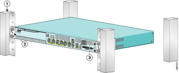
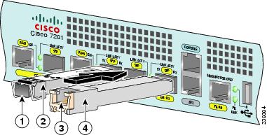
Attach the Rack-Mount Brackets—Chassis Front-Mounted
Figure 1 Attaching the Rack-Mount Brackets to the Front of the Chassis
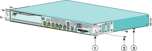
To install the rack-mount brackets on a Cisco 7201 router for a front rack-mount configuration, complete the following steps:
Step 1
Step 2
Step 3
Step 4
Step 5
Step 6
To install the cable-management bracket, see page 7. If you are not installing the cable-management bracket, skip to the "Two-Post Rack Installation" section or the "Four-Post Rack Installation" section for rack-mount instructions.
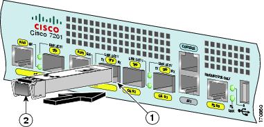
Attach the Rack-Mount Brackets—Chassis Rear-Mounted
Figure 2 Attaching the Rack-Mount Brackets to the Rear of the Chassis
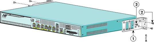
To install the rack-mount brackets on a Cisco 7201 router for a rear rack-mount configuration, complete the following steps:
Step 1
Step 2
Step 3
Step 4
Step 5
Step 6
To install the cable-management bracket, see page 7. If you are not installing the cable-management bracket, skip to the "Two-Post Rack Installation" section or the "Four-Post Rack Installation" section for rack-mount instructions.
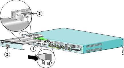
Attach the Cable-Management Bracket
Figure 3 Installing the Cable-Management Bracket
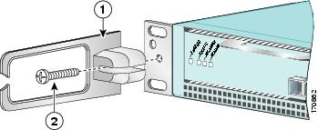
Step 1
Step 2
This completes the procedure for installing the cable-management bracket on a Cisco 7201 router. Go to the "Two-Post Rack Installation" section or the "Four-Post Rack Installation" section.
Two-Post Rack Installation

Note
Figure 4 Installing the Cisco 7201 Router in a Two-Post Rack
Step 1
Step 2
Step 3
Step 4
Step 5
Step 6
This completes the procedure for installing the chassis in the rack. Proceed to the "Chassis Ground Connection Installation" section to continue the installation.
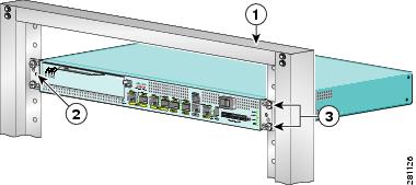
Four-Post Rack Installation
Note
Figure 5 Installing the Cisco 7201 Router in a Four-Post Rack
Step 1
Step 2
Step 3
Step 4
Step 5
Step 6
This completes the procedure for installing the chassis in the rack. Proceed to the "Chassis Ground Connection Installation" section to continue the installation.
Chassis Ground Connection Installation
Before you connect power or turn on power to your router, you must provide an adequate chassis ground (earth) connection for the router chassis. A chassis ground connector is provided on each Cisco 7201 router chassis.
Figure 6 Locating the Chassis Ground Connector

Step 1
Step 2
Step 3
Figure 7 Attaching the Grounding Lug
Step 4
Figure 8 Attaching a Grounding Lug to the Chassis Ground Connector
Step 5
Step 6
Step 7
Step 8
This completes the procedure for attaching a chassis ground connection. Go to the "Connect the Router to the Network" section for information on attaching cables.
4 Connect the Router to the Network
This section provides information about cables and ports and attaching the router to the network.
•
•
•
•
•
Warning
Console and Auxiliary Port Cable Connections
Figure 9 Console and Auxiliary Port RJ-45 Connectors
Auxiliary port
Cable to console terminal or DTE
Console port
Cable to modem or DCE
RJ-45 connector
Step 1
Step 2
The Cisco 7201 router uses RJ-45 ports for both the auxiliary port and the console port.
Note
Table 1 Pinouts for the RJ-45-to-DB-25 Adapters
1
4
5
5
2
20
6
8
3
2
3
3
4
7
7
7
5
7
7
7
6
3
2
2
7
6
20
20
8
5
4
4
1 The female data terminal equipment (FDTE) adapter that is available from Cisco is labeled "Terminal".
2 The MMOD adapter that is available from Cisco is labeled "Modem".
Refer to Table 1 for a list of the pins used on the RJ-45-to-DB-25 adapters, used with an RJ-45 cable, to connect terminals and modems to the Cisco 7201 router. The cable you use may be a roll-over cable or a straight-through cable.
A roll-over cable can be detected by comparing the two modular ends of the cable. Holding the cables in your hand, side-by-side, with the tab at the back, the wire connected to the pin on the outside of the left plug should be the same color as the pin on the outside of the right plug. If your cable was purchased from Cisco, pin 1 will be white on one connector, and pin 8 will be white on the other (a roll-over cable reverses pins 1 and 8, 2 and 7, 3 and 6, and 4 and 5). (See Figure 10.)
Figure 10 Identifying a Roll-Over Cable
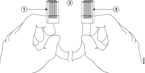
The Cisco 7201 router ships with a roll-over cable. Connection to a terminal or a modem will require an RJ-45-to-DB-25 adapter, and possibly a DB-25-to-DB9 adapter. Refer to Table 2 for the cable and adapter configurations that can be used to connect terminals and modems to the Cisco 7201 router.
Table 2 Asynchronous Device Cabling Options
Console or auxiliary
Roll-over
FDTE1
Terminal
Console or auxiliary
Straight-through
FDCE
Terminal
Auxiliary or console
Roll-over
MMOD2
Modem
1 The FDTE RJ-45-to-DB-25 adapter is labeled "Terminal".
2 The MMOD RJ-45-to-DB-25 adapter is labeled "Modem".
Connect the Fast Ethernet Management Port Cable
Figure 11 Installing the Fast Ethernet Management Port Cable
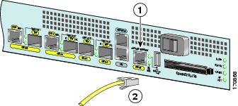
When using the Fast Ethernet Management port in the default mode (speed-auto and duplex-auto) the port operates in auto-MDI/MDI-X mode. The port automatically provides the correct signal connectivity through the Auto-MDI/MDI-X feature. The port automatically senses a crossover or straight-through cable and adapts to it.
However, when the Fast Ethernet Management port is configured to a fixed speed (10 or 100 Mbps) through command-line interface (CLI) commands, the port is forced to MDI mode.
When in a fixed-speed configuration and MDI mode:
•
•
Connect Native Gigabit Ethernet Cables
The Cisco 7201 router native Gigabit Ethernet ports use either optical fiber or RJ-45 Ethernet cables. For installation information see:
•
•
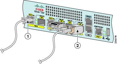
The SFP port is a 1000-Mbps optical interface in the form of an LC-type duplex port that supports IEEE 802.3z interfaces compliant with the 1000BASEX standard. (See Figure 13.)
Appendix A, "Specifications" of the online Cisco 7201 Installation and Configuration Guide, provides cabling specifications and configuration information for the SFP modules that you install in the Gigabit Ethernet SFP ports.
Warning
Figure 13 shows the duplex LC-type connectors on your multimode or single-mode optical fiber cables. For simplex connectors, two cables are required, one cable for transmit (TX) and a second cable for receive (RX). For duplex connectors, only one cable that has both TX and RX connectors is required. You can use either simplex or duplex connectors to the SFP ports on the
Cisco 7201 router.Install the SFP Module Optical Fiber Cables
The SFP module ports support IEEE 802.3z (optical Gigabit Ethernet) interfaces compliant with 1000BASESX and 1000BASELX specifications.
SFP modules ordered with the Cisco 7201 router come installed in the system. Optical fiber cables are commercially available; they are not available from Cisco.
Figure 12 Optical SFP Modules and Copper SFP Modules
The optical SFP modules can occupy any of the four optical Gigabit Ethernet ports, 0/0 through 0/3. However, the copper SFP modules can occupy only optical Gigabit Ethernet ports 0/2 and 0/3.
Figure 13 SFP Port Connections
To external 1000BASEX network
TX (SFP port 0/1)
Duplex connector (TX and RX)
RX (SFP port 0/1)
SFP module
Note
Inspection and Cleaning Procedures for Fiber-Optic Connections document at http://www.cisco.com/en/US/tech/tk482/tk876/technologies_white_paper09186a0080254eba.shtml. It provides detailed illustrations and photos of procedures and equipment required to properly clean fiber-optic connections.
Also see the Compressed Air Cleaning Issues for Fiber-Optic Connections document at http://www.cisco.com/en/US/tech/tk482/tk611/technologies_white_paper09186a00801b08da.shtml.
Warning
Warning
Step 1
Warning
Step 2
•
•

Caution
Mode-Conditioning Patch Cord Description
A mode-conditioning patch cord can be used with the SFP-GE-L= (SFP module) to allow reliable laser transmission between the single-mode laser source on the SFP module and a multimode optical fiber cable.
When an unconditioned laser source designed for operation on single-mode optical fiber is directly coupled to a multimode optical fiber cable, an effect known as differential mode delay (DMD) might result in a degradation of the modal bandwidth of the optical fiber cable.
This degradation results in a decrease in the link span (the distance between a transmitter and a receiver) that can be supported reliably. The effect of DMD can be overcome by conditioning the launch characteristics of a laser source. A practical means of performing this conditioning is to use a device called a mode-conditioning patch cord.
A mode-conditioning patch cord is an optical fiber cable assembly that consists of a pair of optical fibers terminated with connector hardware. Specifically, the mode-conditioning patch cord is composed of a single-mode optical fiber permanently coupled off-center (see Offset in Figure 14) to a graded-index multimode optical fiber. Figure 14 shows a diagram of the mode-conditioning patch cord assembly.
Figure 14 Mode-Conditioning Patch Cord Assembly for an SFP Module
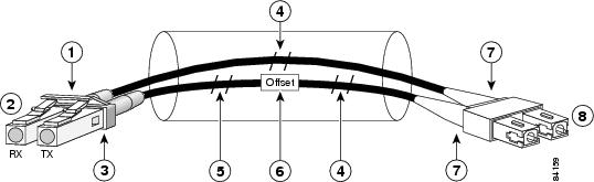
Gray color identifier
Single-mode bar
To Gigabit Ethernet interface
Offset
Blue color identifier
Beige color identifier
Multimode bar
To cable plant
The mode-conditioning patch cord assembly is composed of duplex optical fibers, including a single-mode-to-multimode offset launch fiber connected to the transmitter, and a second conventional graded-index multimode optical fiber connected to the receiver. The use of a plug-to-plug patch cord maximizes the power budget of multimode 1000BASE-LX and 1000BASE-LH links.
The mode-conditioning patch cord is required to comply with IEEE standards. The IEEE found that link distances could not be met with certain types of fiber-optic cable cores. The solution is to launch light from the laser at a precise offset from the center, which is accomplished by using the mode-conditioning patch cord. At the output of the patch cord, the SFP-GE-L= is compliant with the IEEE 802.3z standard for 1000BASE-LX.
Note
Inspection and Cleaning Procedures for Fiber-Optic Connections document at http://www.cisco.com/en/US/tech/tk482/tk876/technologies_white_paper09186a0080254eba.shtml and the
Compressed Air Cleaning Issues for Fiber-Optic Connections document at http://www.cisco.com/en/US/tech/tk482/tk611/technologies_white_paper09186a00801b08da.shtml. Figure 14 shows one type of mode-conditioning patch cord.
Attach the Mode-Conditioning Patch Cord
To use a mode-conditioning patch cord, follow these steps:
Step 1
For information about cleaning fiber-optic cable connectors and receptacles, see the
Inspection and Cleaning Procedures for Fiber-Optic Connections document at http://www.cisco.com/en/US/tech/tk482/tk611/technologies_white_paper09186a00801b08da.shtml and the
Compressed Air Cleaning Issues for Fiber-Optic Connections document at http://www.cisco.com/en/US/tech/tk482/tk611/technologies_white_paper09186a00801b08da.shtml.Step 2
Step 3
Ensure that you connect the TX and RX ports on one end of the patch cord to the RX and TX ports (respectively) on the other end. Connect TX to RX and RX to TX.
Install the Native Gigabit RJ-45 Ethernet Cables
This section provides information about installing the native Gigabit Ethernet RJ-45 cables.
Intra-Building Lightning Protection
Shielded cables, which are grounded at both ends, are required to be used on the 10/100/1000 Gigabit Ethernet RJ-45 ports in order to be in compliance with requirement R4-11 in GR-1089-Core for a Central Office environment. This is not a requirement for customer premises installations.
Warning
Connect the Cables
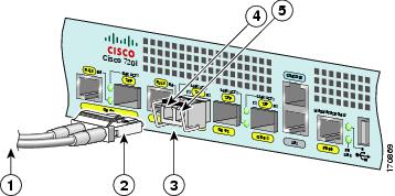
Figure 15 RJ-45 Port and Copper SFP RJ-45 Gigabit Ethernet Port Cabling
Step 1
Step 2
Connect the Port Adapter Cables
The instructions for connecting the cables for the port adapter installed in the Cisco 7201 router are contained in the respective configuration notes for each port adapter. For example, if you are connecting the optical fiber cables for the PA-GE port adapter, refer to the PA-GE Gigabit Ethernet Port Adapter Installation and Configuration document at
Port adapter documents are also available on the Cisco Documentation DVD.
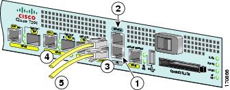
Install the Cables in the Cable-Management Bracket
Figure 16 Securing Interface Cables Through the Cable-Management Bracket
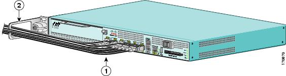
Secure port adapter interface cables and I/O cables by placing them through the cable-management bracket.
Proceed to the "Start the System" section to complete the installation.
5 Start the System
Before you start the system, you must connect power to it.
Connect Power to the Router
•
•
Warning
Warning
Warning
Warning
Connect AC-Input Power
This section provides instructions for installing the AC power supply.
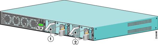
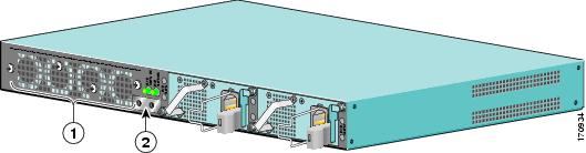
The Cisco 7201 router has two of the same type of power supplies in power supply slot 1 and power supply slot 2. (See Figure 17.) The power supply slot numbers are on the chassis to the left of the left power supply, and to the right of the right power supply.
Figure 17 Power Supply Slot 1 and Slot 2
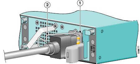
Connect an AC-input power supply as follows:
Figure 18 Connecting AC-Input Power
Step 1
Step 2
Step 3
Step 4
Step 5
Step 6
Note
Note
This completes the procedure for connecting AC-input power. Your installation is complete. Proceed to the "Start the Router" section to start the router and to perform a basic configuration.
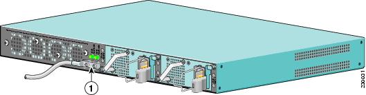
Connect DC-Input Power
This section provides instructions for installing the DC power supply ground leads and installing the DC-input power leads.
Figure 19 Power Supply Slot 1 and Slot 2
The Cisco 7201 has two of the same type of power supplies in power supply slot 1 and power supply slot 2. (See Figure 19.) The power supply slot numbers are on the chassis to the left of the left power supply, and to the right of the right power supply.
Caution
Warning
Warning
Warning
Warning
Caution
Obtain these necessary tools and equipment:
•
•
•
•
•
Install the DC Grounding Leads
To install the DC grounding leads on the DC power supply, follow these instructions.
The DC power supply ships with the DC power supply ground lugs, star washers, and nut attached to the grounding stud on the DC power supply.
Figure 20 Locating the DC Grounding Stud and Grounding Materials
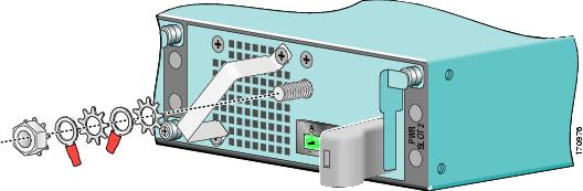
Step 1
Step 2
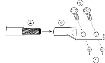
Figure 21 Stripping the DC-Input Power Ground Wire
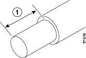
Step 3
Step 4
Step 5
Figure 22 Placing the Ground Lugs, Star Washers, and Nut
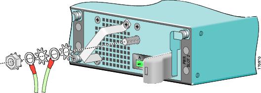
Step 6
a.
b.
c.
d.
e.
Step 7
Step 8
Step 9
Wire the DC-Input Power Source
Note
Warning
Warning
Warning
Statement 1003
Warning
Statement 1030
Use these instructions to wire the DC-input power source:
Step 1
Step 2
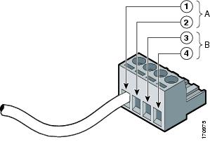
Figure 23 Terminal Block Plug
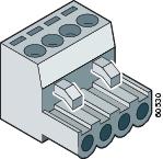
Step 3
Step 4
Figure 24 Positive and Negative Positions
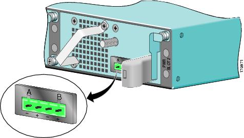
The rear panel of the power supply unit identifies the positive and negative positions for both the A and B feed wires. See Figure 26.
Figure 25 Stripping the DC-Input Power Source Wire
Step 5
Warning
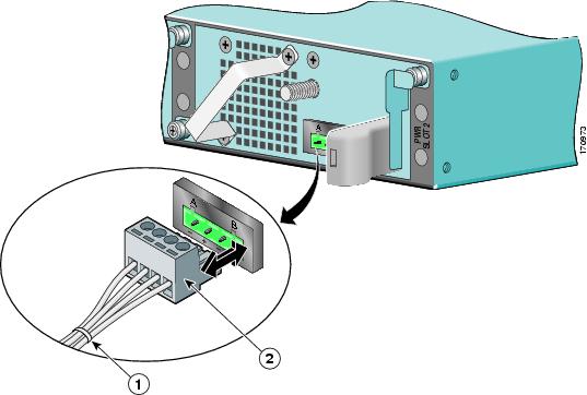
Figure 26 Inserting Wires into the Terminal Block Plug
Step 6
Figure 27 Torquing the Terminal Block Plug Captive Screws
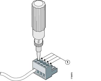
Caution
Step 7
Figure 28 Completed Wiring of Terminal Block Plug
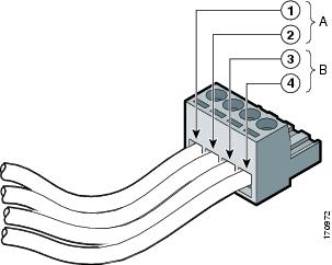
Step 8
Note
Figure 29 Inserting the Terminal Block Plug in the Block Header
Caution
Step 9
Step 10
Step 11
Step 12
Step 13
Step 14
Note
This completes the procedure for connecting DC-input power. Your installation is complete. Proceed to the "Start the Router" section to start the router.
Start the Router
Check the following conditions before you start your router:
•
•
•
•
•
•
•
Step 1
Step 2
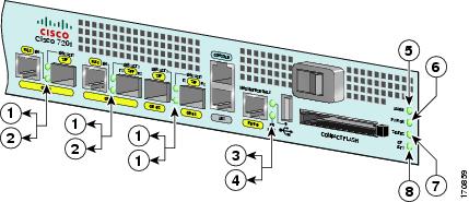
Figure 30 Cisco 7201 Router—Faceplate LEDs
Step 3
Step 4
Proceed to the "Configure the Router" section to configure the router.
6 Configure the Router
Use this section for information on configuring the Cisco 7201 router.
Perform a Basic Configuration Using AutoInstall
The AutoInstall process is designed to configure the Cisco 7201 router automatically after connection to your WAN. For AutoInstall to work properly, a TCP/IP host on your network must be preconfigured to provide the required configuration files. The TCP/IP host may exist anywhere on the network as long as the following two conditions are maintained:
1.
2.
This functionality is coordinated by your system administrator at the site where the TCP/IP host is located. You should not use AutoInstall unless the required files are available on the TCP/IP host. Refer to the Cisco IOS Configuration Fundamentals Configuration Guide and Cisco IOS Configuration Fundamentals Command Reference publications for information about how AutoInstall works.
Complete the following steps to prepare your Cisco 7201 router for the AutoInstall process:
Step 1
Step 2
Step 3
Step 4
Hostname# copy running-config startup-config
Note
Perform a Basic Configuration Using the Setup Facility
If you do not plan to use AutoInstall, do not connect the router's serial (WAN) cable to the channel service unit/data service unit (CSU/DSU). If the WAN cable is not connected, the router boots from flash memory and goes automatically into the setup facility.
Note
If the serial (WAN) cable is connected to the CSU/DSU and the router does not have a configuration stored in NVRAM, the router attempts to run AutoInstall at startup. The router may take several minutes to determine that AutoInstall is not set up to a remote TCP/IP host. Once the router determines that AutoInstall is not configured, it defaults to the setup facility.
Configure Global Parameters
When you first start the setup program, you must configure the global parameters. These parameters are used for controlling system-wide settings. Complete the following steps to enter the global parameters:
Step 1
The system boots from flash memory. The following information appears after about 30 seconds. When you see this information, you have successfully booted your router:
Restricted Rights LegendUse, duplication, or disclosure by the Government is subject to restrictions as set forth in subparagraph (c) of the Commercial Computer Software - Restricted Rights clause at FAR sec. 52.227-19 and subparagraph (c) (1) (ii) of the Rights in Technical Data and Computer Software clause at DFARS sec. 252.227-7013.cisco Systems, Inc. 170 West Tasman Drive San Jose, California 95134-1706Cisco IOS Software, 7200 Software (C7200P-ADVENTERPRISEK9-M), Version 12.4(TAZ3XD.2006-12-03), INTERIM SOFTWARE Copyright (c) 1986-2006 by Cisco Systems, Inc. Compiled Sun 03-Dec-06 00:44 by Image text-base: 0x0000A3F8, data-base: 0x0327A000This product contains cryptographic features and is subject to United States and local country laws governing import, export, transfer and use. Delivery of Cisco cryptographic products does not imply third-party authority to import, export, distribute or use encryption. Importers, exporters, distributors and users are responsible for compliance with U.S. and local country laws. By using this product you agree to comply with applicable laws and regulations. If you are unable to comply with U.S. and local laws, return this product immediately.A summary of U.S. laws governing Cisco cryptographic products may be found at: http://www.cisco.com/wwl/export/crypto/tool/stqrg.htmlIf you require further assistance please contact us by sending email to export@cisco.com.Cisco 7201 (c7201) processor (revision A) with 917504K/65536K bytes of memory. Processor board ID 4294967295 MPC7448 CPU at 1666Mhz, Implementation 0, Rev 2.1 1 slot midplane, Version 2.255Last reset from power-on 1 FastEthernet interface 4 Gigabit Ethernet interfaces 4 Channelized T1/PRI ports 2045K bytes of NVRAM.250200K bytes of ATA PCMCIA card at slot 0 (Sector size 512 bytes). 65536K bytes of Flash internal SIMM (Sector size 512K).Press RETURN to get started!The first two sections of the configuration script (the banner and the installed hardware) appear only at initial system startup. On subsequent uses of the setup facility, the script begins with a System Configuration Dialog as shown in the following example.
--- System Configuration Dialog ---Step 2
Would you like to enter the initial configuration dialog? [yes/no] yesAt any point you may enter a question mark '?' for help.Use ctrl-c to abort configuration dialog at any prompt.Default settings are in square brackets '[]'.Basic management setup configures only enough connectivity for management of the system, extended setup will ask you to configure each interface on the system.Step 3
Would you like to enter the basic management setup [yes/no]: noStep 4
First, would you like to see the current interface summary? [yes]:In the following example, the summary shows a Cisco 7201 router at first-time startup; that is, nothing is configured.
Interface          IP-Address     OK?    Method   Status    Protocol
FastEthernet0/0    unassigned     NO     unset    up        up
GigabitEthernet0/0 unassigned     NO     unset    up        up
GigabitEthernet0/1 unassigned     NO     unset    up        up
GigabitEthernet0/2 unassigned     NO     unset    up        up
GigabitEthernet0/3 unassigned     NO     unset    up        up
Step 5
Configuring global parameters:Enter host name [Router]:Step 6
The enable secret is a password used to protect access to privileged EXEC and configuration modes. This
password, after entered, becomes encrypted in the configuration.
Enter enable secret: barney
The enable password is used when you do not specify an enable secret password, with some older software versions, and some boot images. Enter enable password: bettyThe virtual terminal password is used to protect access to the router over a network interface.Enter virtual terminal password: fredStep 7
Configure System Management? [yes/no]: noStep 8
Enter yes or press Return to accept SNMP management; enter no to refuse it:
Configure SNMP Network Management? [yes]: noCommunity string [public]:Step 9
Configure LAT? [no]:Configure IP? [yes]:Configure RIP routing? [no]:Configure bridging? [no]:Configure AppleTalk? [no]:Configure DECnet? [no]:Configure CLNS? [no]:Configure IPX? [no]:Step 10
To configure IP routing, enter yes (the default) or press Return, and then select an interior routing protocol:
Do you want to configure FastEthernet0/0 interface? [yes]:
Use the 100 Base-TX (RJ-45) connector? [yes]:
Operate in full-duplex mode? [no]: yes
Configure IP on this interface? [yes]:
IP address for this interface: 10.2.2.1
Subnet mask for this interface [255.0.0.0] : 255.255.255.0
Class A network is 10.0.0.0, 24 subnet bits; mask is /24
Do you want to configure GigabitEthernet0/0 interface? [yes]: Configure IP on this interface? [yes]: IP address for this interface: 25.2.4.10 Subnet mask for this interface [255.0.0.0] : 255.255.0.0 Class A network is 25.0.0.0, 16 subnet bits; mask is /16Do you want to configure GigabitEthernet0/1 interface? [yes]: Configure IP on this interface? [yes]: IP address for this interface: 70.1.1.2 Subnet mask for this interface [255.0.0.0] : 255.255.255.0 Class A network is 70.0.0.0, 24 subnet bits; mask is /24Do you want to configure GigabitEthernet0/2 interface? [yes]: noDo you want to configure GigabitEthernet0/3 interface? [yes]: noWould you like to go through AutoSecure configuration? [yes]: no AutoSecure dialog can be started later using "auto secure" CLIThe following sample display includes a continuous listing of all configuration parameters selected in Step 5 through Step 10. Only IP is the selected protocol for this example.
Configuring global parameters:Enter host name [Router]: routerThe enable secret is a one-way cryptographic secret used instead of the enable password when it exists.
Enter enable secret: barneyThe enable password is used when there is no enable secret and when using older software and some boot images.Enter enable password: bettyline vty 0 4 password cisco no snmp-server ! ip routing no bridge 1 no appletalk routing no decnet routing no clns routing no ipx routing ! interface FastEthernet0/0 media-type 100BaseX full-duplex ip address 10.2.2.1 255.255.255.0 no mop enabled ! interface GigabitEthernet0/0 ip address 25.2.4.10 255.255.0.0 no mop enabled ! interface GigabitEthernet0/1 ip address 70.1.1.2 255.255.255.0 no mop enabled ! interface GigabitEthernet0/2 shutdown no ip address ! interface GigabitEthernet0/3 shutdown no ip address ! endStep 11
[0] Go to the IOS command prompt without saving this config.
[1] Return back to the setup without saving this config.
[2] Save this configuration to nvram and exit.
Enter your selection [2]: 2 media-type 100BaseXBuilding configuration... Use the enabled mode 'configure' command to modify this configuration.Press RETURN to get started!
Configure the Native Gigabit Ethernet Interfaces
The Cisco 7201 router reports the Gigabit Ethernet SFP ports as GigabitEthernet 0/0, GigabitEthernet 0/1, GigabitEthernet 0/2, and GigabitEthernet 0/3. The Cisco 7201 router reports the RJ-45 ports as GigabitEthernet 0/0 and Gigabit Ethernet 0/1. Before configuring either the GigabitEthernet 0/0 or Gigabit Ethernet 0/1 interfaces, you must first use the media-type interface command to select the media type, sfp or rj45.
Changing the Media Type
To be able to use a particular media type, use Cisco IOS to select the media type. This is done by using the media-type interface command:
media-type { sfp | rj45 }
Example:
interface GigabitEthernet 0/0media-type rj45endConfiguring the Interface Transmission and Speed Modes
After changing the media type, configure the speed and duplex transmission modes to appropriately match the new interface characteristics. Changing the speed and duplex of a Cisco 7201 router Gigabit Ethernet interface is done using the speed and duplex interface commands.
Table 3 Supported Speed and Duplex Settings
SFP
1000, auto
full, half, auto1
RJ-45
10, 100, 1000, auto
full, half, auto
1 GE 0/3 only supports full duplex mode.
When using the sfp media type, there is also the additional negotiation auto command that is used to enable the IEEE 802.1z Gigabit Ethernet (1000 Mbps) autonegotiation protocol.
To turn this negotiation auto feature off (it is on by default), issue the interface command
no negotiation auto. This is useful for connecting to other Gigabit Ethernet equipment that does not support IEEE 802.1z autonegotiation. We recommended that a fixed speed and duplex setting should be used.When the interface is configured for negotiation auto, the interface advertises all modes of which it is capable. The link only comes up if the negotiation process succeeds in finding a common mode between the Cisco 7201 SFP media type and its link partner.
The sfp media type always defaults to 1000-Mbps, full-duplex operation. The only available speed in this mode is 1000 Mbps; there is no difference whether 1000 or auto is selected. GE 0/0, GE 0/1 and GE 0/2 support half and full duplex mode; GE 0/3 only supports full duplex mode.
Note
Note
When an RJ-45 interface is enabled, it advertises all modes of which it is capable. The link only comes up if the negotiation process succeeds in finding a common mode between the Cisco 7201 RJ-45 media type and its link partner.
If you change from the sfp to the rj-45 media type, you must set speed and duplex after you have executed the media type command to ensure the interface operates in the correct mode.
For information on flow control, see the Cisco 7201 Installation and Configuration Guide, Appendix A, "Gigabit Ethernet Flow Control Information" section.
Debug Information
Cisco IOS provides two commands to provide information on your interfaces: show interface GigabitEthernet 0/X (where X is 0, 1, 2, or 3) and show controllers GigabitEthernet 0/X (where X is 0, 1, 2, or 3).
The output of the show interface command is useful for determining the current operating mode of the interface (speed/duplex/media type) and the current interface statistics.
The output of the show controllers command displays more information specific to the Cisco 7201 router Gigabit Ethernet interface. For example, it shows the detected link status, speed, and duplex, and also determines the current status of autonegotiation and the link partners' abilities (if it is an autonegotiation-capable interface).
The show controllers command also displays the current operating state of the driver and the Ethernet controller hardware. The show controllers command is a very powerful debugging aid, especially for Cisco engineers should you need help in debugging a problem. If you have any problems with your Gigabit Ethernet interfaces, you will need to provide this information to Cisco for analysis.
Reset the Interface
Should you have a problem with your interface and you want to try and reset it, use the command:
clear interface GigabitEthernet 0/X (where X is 0, 1, 2, or 3)
Clear Counters
Interface counters may be cleared (reset) by using the command:
clear counters GigabitEthernet 0/X (where X is 0, 1, 2, or 3)
Note
Configure Port Adapter Interfaces
Following are the steps for configuring interfaces to allow communication over a LAN or WAN. To configure the interface parameters, you need your interface network addresses and subnet mask information. Consult with your network administrator for this information.
Note
Configure ATM Interfaces
In the following example, an ATM interface in slot 1 is configured for an ATM LAN using IP. Follow these steps to configure an ATM interface:
Step 1
Configuring interface parameters:Configuring interface ATM1/0:I this interface in use? [yes]:Configure IP on this interface? [yes]:IP address for this interface: 1.1.1.10Number of bits in subnet field [0]:Class C network is 1.1.1.0, 0 subnet bits; mask is /24Step 2
Configure IPX on this interface? [no]: yesIPX network number [2]:Step 3
Configure AppleTalk on this interface? [no]: yesExtended AppleTalk network? [no]: yesAppleTalk starting cable range [0]:Step 4
Note
Configure Fast Ethernet Interfaces
In the following example, a Fast Ethernet interface in slot 1 is configured for a Fast Ethernet LAN using IP. Follow these steps to configure Fast Ethernet interfaces:
Step 1
Configuring interface parameters:Configuring interface FastEthernet1/0:Is this interface in use? [yes]:Use the 100 Base-TX (RJ-45) connector? [yes]:Operate in full-duplex mode? [no]:Configure IP on this interface? [yes]:IP address for this interface: 1.1.1.20Numbr of bits in subnet field [0]:Class C network is 1.1.1.0, 0 subnet bits; mask is /24Step 2
Configure IPX on this interface? [no]: yesIPX network number [2]:Step 3
Configure AppleTalk on this interface? [no]: yesExtended AppleTalk network? [no]: yesAppleTalk starting cable range [0]:Step 4
Note
Configure Synchronous Serial Interfaces
Synchronous serial interfaces are configured to allow connection to WANs through a CSU/DSU. In the following example, a synchronous serial interface in slot 1 is configured for a WAN connection using IP. Follow these steps to configure synchronous serial interfaces:
Step 1
Configuring interface parameters:Configuring interface serial 1/0:Is this interface in use? [yes]:Configure IP on this interface? [yes]:IP address for this interface: 1.1.1.30Number of bits in subnet field [0]:Class A network is 1.1.1.0, 0 subnet bits; mask is /24Step 2
Configure IPX on this interface? [no]: yesIPX network number [2]:Step 3
Configure AppleTalk on this interface? [no]: yesExtended AppleTalk network? [no]: yesAppleTalk starting cable range [0]:Step 4
Note
The following example display lists the ATM configuration parameters:
Configuring interface ATM1/0:Is this interface in use? [yes]:Configure IP on this interface? [yes]:IP address for this interface: 1.1.1.10Number of bits in subnet field [0]: 0Class C network is 1.1.1.0, 0 subnet bits; mask is /24Configure IPX on this interface? [yes]:IPX network number [2]:Configure AppleTalk on this interface? [no]: yesExtended AppleTalk network? [no]: yesAppleTalk starting cable range [0]:The following configuration command script was created:hostname Routerenable secret 5 $1$u8z3$PMYY8em./8sszhzk78p/Y0enable password bettyline vty 0 4password fredsnmp-server community public!ip routingno vines routingipx routingappletalk routingno apollo routingno decnet routingno xns routingno clns routingno bridge 1! Turn off IPX to prevent network conflicts.interface ATM1/0ip address 1.1.1.10 255.0.0.1appletalk cable-range 0-0 0.0appletalk discovery!router igrp 15network 1.0.0.0!endUse this configuration? [yes/no]: yesBuilding configuration...Use the enabled mode `configure' command to modify this configuration.Press RETURN to get started!Your router is now minimally configured and ready to use. You can use the setup command if you want to modify the parameters after the initial configuration. To perform more complex configurations, use the configure command.
For information on additional interface configuration and specific system configurations, refer to the modular configuration and modular command reference publications in the Cisco IOS software configuration documentation set that corresponds to the software release installed on your Cisco hardware.
Check the Running Configuration Settings
To check the value of the settings you have entered, enter the show running-config command at the Router# prompt:
Router# show running-configTo review changes you make to the configuration, use the EXEC mode show startup-config command to see the changes and copy run-start stored in NVRAM.
Save the Running Configuration to NVRAM
To review changes you make to the configuration, use the EXEC mode show startup-config command to display the information stored in NVRAM.
To store the configuration or changes to your startup configuration in NVRAM, enter the copy running-config startup-config command at the Router# prompt:
Router# copy running-config startup-configUsing this command saves the configuration settings that you created in the router using configuration mode and the setup facility. If you fail to do this, your configuration will be lost the next time you reload the router.
Perform Other Configuration Tasks
To make advanced configuration changes after you establish the basic startup configuration for your router, refer to the modular configuration and modular command reference publications in the Cisco IOS software configuration documentation set that corresponds to the software release installed on your Cisco hardware. These publications contain additional information on using the configure command.
The configuration publications also provide information about the following tasks:
•
•
•
•
•
Replace or Recover a Lost Password
See the Cisco 7201 Installation and Configuration Guide, Chapter 3, "Starting and Configuring the Router," for instructions on replacing or recovering a lost password. It is possible to recover the enable or console login password. The enable secret password is encrypted and must be replaced with a new enable secret password.
Troubleshoot a Problem
For system start-up troubleshooting information, see the online Cisco 7201 Router Troubleshooting Module accessed from the Cisco 7201 Router Troubleshooting Documentation Roadmap at http://www.cisco.com/en/US/docs/routers/7200/roadmaps/7201_trblshoot_doc_roadmap/11367tr.html
7 After Installation
Follow the instructions in this section to replace field-replaceable units (FRUs) after installation. Use the installation and removal information in this section to power off the router, remove the cover, replace the FRU, replace the cover, and power on the router. The following topics are covered in this section:
•
•
•
•
•
•
Warning
Statement 1030
Warning
Warning
Warning
Warning
Power Off the Cisco 7201 Router
Step 1
Step 2
a.
b.
Note
Replace the CompactFlash Disk
Figure 31 Installing and Removing a CompactFlash Disk
Step 1
Note
Step 2
Note
•
•
•
For more information on the CompactFlash Disk, see Appendix B, "Using the CompactFlash Disk," in the Cisco 7201 Installation and Configuration Guide at http://www.cisco.com/en/US/docs/routers/7200/install_and_upgrade/7201_install_config/7201_icg.html.
Replace the USB Flash Memory Module
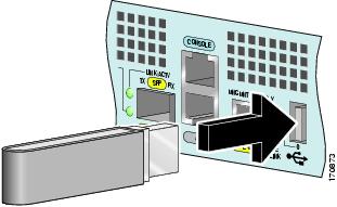
Figure 32 Installing a USB Flash Memory Module
Note
Caution
Step 1
Note
Step 2
Remove and Replace an SFP Module
Warning
Warning
Warning
Warning
For general information about SFP modules, see the Chapter 4 of the Cisco 7201 Installation and Configuration Guide, the "Removing and Installing an SFP Module" section.
Figure 33 Optical SFP Module and Copper SFP Module
Optical SFP module plug
Copper SFP module RJ-45 connector
Optical SFP module
Copper SFP module
The optical SFP modules can occupy any of the four optical Gigabit Ethernet ports, 0/0 through 0/3. However, the copper SFP modules can occupy only optical Gigabit Ethernet ports 0/2 and 0/3.
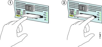
Figure 34 Inserting an SFP Module into the Cisco 7201 Gigabit Ethernet Port 0/1
Use the following procedure to remove an SFP module:
Step 1
Step 2
Step 3
Step 4
Step 5
Use the following procedure to install an SFP module:
Step 1
Step 2
Note
Step 3
Step 4
Note
Step 5
Inspection and Cleaning Procedures for Fiber-Optic Connections document at http://www.cisco.com/en/US/tech/tk482/tk876/technologies_white_paper09186a0080254eba.shtml and the
Compressed Air Cleaning Issues for Fiber-Optic Connections document at http://www.cisco.com/en/US/tech/tk482/tk611/technologies_white_paper09186a00801b08da.shtml.
Remove and Replace a Power Supply
This section provides information about removing and replacing an AC or DC power supply. Because of the power supply redundancy, there is no need to power off the Cisco 7201 router before removing one of the AC or DC power supplies.
The Cisco 7201 has two of the same type of power supplies in power supply slot 1 and power supply slot 2. (See Figure 35.)
Figure 35 Power Supply Slot 1 and Slot 2
Remove the AC Power Supply
Step 1
Figure 36 Removing the AC Power Cable
Step 2
Step 3
Figure 37 Removing the AC Power Supply
Power up restrictor
Lower power supply captive installation screw
Upper power supply captive installation screw
Step 4
Step 5
Step 6
Step 7
Caution
Install the AC Power Supply
This section provides information about installing an AC power supply in the Cisco 7201 router.
Note
Warning
Warning
Figure 38 Installing the AC Power Supply
Power up restrictor
Lower power supply captive installation screw
Upper power supply captive installation screw
Step 1
Step 2
a.
b.
c.
Step 3
Step 4
Step 5
Step 6
Step 7
Note
Remove the DC Power Supply
Because of the power supply redundancy, there is no need to power off the Cisco 7201 router before removing one of the DC power supplies.
Warning
Statement 1003
Warning
Statement 1030
Warning
Figure 39 Removing the Ground Lugs
Caution
Step 1
Step 2
Step 3
Step 4
Step 5
Step 6
Step 7
Step 8
Install the DC Power Supply
Warning
Warning
This section provides instructions for installing the DC power supply ground leads and installing the DC-input power leads.
Caution
Warning
Obtain these necessary tools and equipment:
•
•
•
•
•
Install the DC Grounding Leads
To install the DC grounding leads on the DC power supply, follow these instructions.
The DC power supply ships with the DC power supply ground lugs, star washers, and nut attached to the grounding stud on the DC power supply.
•
•
Figure 40 Locating the DC Grounding Stud and Grounding Materials
Step 1
Step 2
Place the ground lugs, star washers, and nut on the grounding stud in this order:
a.
b.
c.
d.
e.
Step 3
Wire the DC-Input Power Source
Note
Warning
Warning
Warning
Statement 1003
Warning
Statement 1030
Step 1
Step 2
Figure 41 Inserting the Terminal Block Plug in the Block Header
Caution
Step 3
Step 4
Step 5
Step 6
Step 7
Step 8
Note
Replace the Port Adapter or Service Adapter
The port adapter or service adapter ships installed. These instructions are provided for future use. Cabling information is included with the specific port adapter documentation.
Figure 42 Removing and Installing the Port Adapter
Warning
Before removing any port adapter, gracefully shut down the interface so that there is no traffic running through the port adapter when it is removed. Removing a port adapter while traffic is flowing through the ports can cause system disruption.
Step 1
Step 2
Step 3
Step 4
Step 5
Caution
Step 6
Step 7
Step 8
Step 9
Note
Replace the DIMM
This section provides information about replacing the DIMM.
Power Off the Router and Remove the Cover
This section provides information for powering off the router and removing the cover.
Warning
Warning
Step 1
Step 2
Note
Step 3
Step 4
Step 5
Figure 43 Removing the Cover
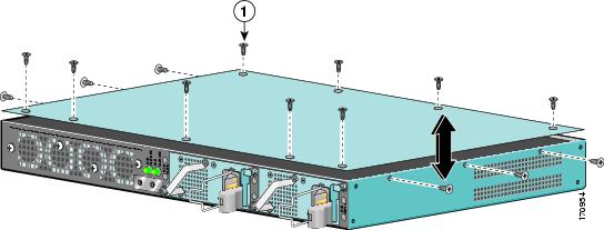
Step 6
Step 7
Step 8
Remove and Install the DIMM
The information in this section provides instructions for replacing the DDR-SDRAM DIMM. The memory configuration you ordered is installed in the Cisco 7201 router.
Warning
To replace or upgrade the DIMM, follow these instructions:
Figure 44 Removing and Replacing the DIMM
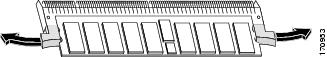
Note
Step 1
Step 2
Step 3
Step 4
Caution
Step 5
Step 6
Step 7
For memory specifications and configurations, see Appendix A, "Specifications," of the online Cisco 7201 Installation and Configuration Guide at http://www.cisco.com/en/US/docs/routers/7200/install_and_upgrade/7201_install_config/7201_icg.html
Replace the Cover and Power On the Router
Follow these instructions to replace the cover and power on the router:
Figure 45 Inserting the Screws and Replacing the Cover
Step 1
Step 2
Step 3
Step 4
 Feedback