Cisco NCS 4216 Hardware Installation Guide
Bias-Free Language
The documentation set for this product strives to use bias-free language. For the purposes of this documentation set, bias-free is defined as language that does not imply discrimination based on age, disability, gender, racial identity, ethnic identity, sexual orientation, socioeconomic status, and intersectionality. Exceptions may be present in the documentation due to language that is hardcoded in the user interfaces of the product software, language used based on RFP documentation, or language that is used by a referenced third-party product. Learn more about how Cisco is using Inclusive Language.
- Updated:
- November 17, 2016
Chapter: Preparing for Installation
Preparing for Installation
The sections describe how to prepare for the installation of the Cisco NCS 4216 at your site.
Safety Guidelines
Before you begin the installation of the Cisco NCS 4216, review the safety guidelines in this chapter to avoid injuring yourself or damaging the equipment.
In addition, before replacing, configuring, or maintaining the Cisco NCS 4216, review the safety warnings listed in Regulatory Compliance and Safety Information for the Cisco NCS 4200 Series Aggregation Routers.
The sections describe the safety guidelines for the Cisco NCS 4216.
- Standard Warning Statements
- Safety Guidelines for Personal Safety and Equipment Protection
- Safety Precautions for Module Installation and Removal
- Safety with city
- Power Supply Considerations
- Preventing ESD Damage
Standard Warning Statements
To see translations of the warnings that appear in this publication, refer to the Regulatory Compliance and Safety Information document that accompanied this device.
 Warning | The appliance must be connected to a grounded outlet. Statement 0414 |
Warning | To avoid or reduce the risk of personal injury, do not use the product if the product has been exposed to irregular environmental conditions, if the product has been misused or if parts of the product have been damaged. Consult qualified service personnel. Never try to service the product yourself. Statement 0416 |
Warning | To reduce the risk of c shock, fire or personal injury, do not place power cables in areas where they may be walked on or damaged by items placed upon or against it. Statement 0417 |
Warning | This product is intended for use in a normal environment based on the standard IEC 60950-1. Do not use the product in vehicles, on board ships, in aircrafts or in medical applications with physical connection to the patient, nor in environments with exposure to moisture, dust, vibration or ingress of water. Statement 0418 |
Warning | Do not work on the system or connect or disconnect cables during periods of lightning activity. Statement 1001 |
Warning | Read the installation instructions before connecting the system to the power source. Statement 1004 |
Warning | To prevent bodily injury when mounting or servicing this unit in a rack, you must take special precautions to ensure that the system remains stable. The following guidelines are provided to ensure your safety: This unit should be mounted at the bottom of the rack if it is the only unit in the rack. When mounting this unit in a partially filled rack, load the rack from the bottom to the top with the heaviest component at the bottom of the rack. If the rack is provided with stabilizing devices, install the stabilizers before mounting or servicing the unit in the rack. Statement 1006 |
Warning | This unit is intended for installation in restricted access areas. A restricted access area can be accessed only through the use of a special tool, lock and key, or other means of security. Statement 1017 |
Warning | To reduce the risk of fire, use only No. 26 AWG or larger telecommunication line cord. Statement 1023 |
Warning | If the symbol of suitability with an overlaid cross appears above a port, you must not connect the port to a public network that follows the European Union standards. Connecting the port to this type of public network can cause severe injury or damage your router. Statement 1031 |
Warning | Do not use this product near water; for example, near a bath tub, wash bowl, kitchen sink or laundry tub, in a wet basement, or near a swimming pool. Statement 1035 |
Warning | Never install telephone jacks in wet locations unless the jack is specifically designed for wet locations. Statement 1036 |
Warning | Never touch uninsulated telephone wires or terminals unless the telephone line has been disconnected at the network interface. Statement 1037 |
Warning | Avoid using a telephone (other than a cordless type) during an electrical storm. There may be a remote risk of electric shock from lightning. Statement 1038 |
Warning | To report a gas leak, do not use a telephone in the vicinity of the leak. Statement 1039 |
Warning | Ultimate disposal of this product should be handled according to all national laws and regulations. Statement 1040 |
Warning | Before opening the unit, disconnect the telephone-network cables to avoid contact with telephone-network voltages. Statement 1041 |
Warning | To prevent the system from overheating, do not operate it in an area that exceeds the maximum recommended ambient temperature of 149°F (65°C). Statement 1047 |
Warning | The chassis should be mounted on a rack that is permanently affixed to the building. Statement 1049 |
Warning | Invisible laser radiation may be emitted from disconnected fibers or connectors. Do not stare into beams or view directly with optical instruments. Statement 1051 |
Warning | Class 1M laser radiation when open. Do not view directly with optical instruments. Statement 1053 |
Warning | Class I (CDRH) and Class 1M (IEC) laser products. Statement 1055 |
Warning | No user-serviceable parts inside. Do not open. Statement 1073 |
Warning | This is a Class A Device and is registered for EMC requirements for industrial use. The seller or buyer should be aware of this. If this type was sold or purchased by mistake, it should be replaced with a residential-use type. Statement 294 |
Warning | This is a class A product. In a domestic environment this product may cause radio interference in which case the user may be required to take adequate measures. Statement 340 |
Warning | This equipment is in compliance with the essential requirements and other relevant provisions of Directive 1999/5/EC. |
Safety Guidelines for Personal Safety and Equipment Protection
The following guidelines help ensure your safety and protect the equipment. This list does not include all the potentially hazardous situations. Therefore, you should be on alert.
- Before moving the system, always disconnect all the power cords and interface cables.
- Never assume that power is disconnected from a circuit; always check.
- Before and after installation, keep the chassis area clear and dust-free.
- Keep tools and assembly components away from walk areas where you or others could trip over them.
- Do not work alone if potentially hazardous conditions exist.
- Do not perform any action that creates a potential hazard to people or makes the equipment unsafe.
- Do not wear loose clothing that may get caught in the chassis.
- When working under conditions that may be hazardous to your eyes, wear safety glasses.
Safety Precautions for Module Installation and Removal
Be sure to observe the following safety precautions when you work on the router.
To see translations of the warnings that appear in this publication, refer to the Regulatory Compliance and Safety Information document that accompanied this device.
Warning | For connections outside the building where the equipment is installed, the following ports must be connected through an approved network termination unit with integral circuit protection . Statement 1044 |
Warning | Invisible laser radiation may be emitted from disconnected fibers or connectors. Do not stare into beams or view directly with optical instruments. Statement 1051 |
Warning | Class 1M laser radiation when open. Do not view directly with optical instruments. Statement 1053 |
Warning | Class 1 CDRH) and Class 1M (IEC) laser products. Statement 1055 |
Warning | Invisible laser radiation may be emitted from the end of the unterminated fiber cable or connector. Do not view directly with optical instruments. Viewing the laser output with certain optical instruments (for example, eye loupes, magnifiers, and microscopes) within a distance of 100 mm may pose an eye hazard. Statement 1056 |
Warning | Do not stare into the beam or view it directly with optical instruments. Statement 1011 |
Warning | Invisible laser radiation present. Statement 1016 |
Warning | Blank faceplates and cover panels serve three important functions: they prevent exposure to hazardous voltages and currents inside the chassis; they contain electromagnetic interference (EMI) that might disrupt other equipment; and they direct the flow of cooling air through the chassis. Do not operate the system unless all cards, faceplates, front covers, and rear covers are in place. Statement 1029 |
Warning | Hazardous voltage or energy is present on the backplane when the system is operating. Use caution when servicing. Statement 1034 |
Warning | Invisible laser radiation may be emitted from disconnected fibers or connectors. Do not stare into beams or view directly with optical instruments. Statement 1051 |
Safety with city
Warning | Before working on a chassis or working near power supplies, disconnect the power at the circuit breaker on DC units. Statement 12 |
Warning | Before working on equipment that is connected to power lines, remove jewelry (including rings, necklaces, and watches). Metal objects will heat up when connected to power and ground and can cause serious burns or weld the metal object to the terminals. Statement 43 |
Warning | To prevent accidental discharge in the event of a power line cross, route on-premise wiring away from power cables and off-premise wiring, or use a grounded shield to separate the on-premise wiring from the power cables and off-premise wiring. A power line cross is an event, such as a lightning strike, that causes a power surge. Off-premise wiring is designed to withstand power line crosses. On-premise wiring is protected from power line crosses by a device that provides overcurrent and overvoltage protection. Nevertheless, if the on-premise wiring is in close proximity to or not shielded from, the off-premise wiring or power cable during a lightning strike or power surge, the on-premise wiring can carry a dangerous discharge to the attached interface, equipment, or nearby personnel. Statement 338 |
Warning | High leakage current – earth connection essential before connection to system power supply. Statement 342 |
Warning | Do not work on the system or connect or disconnect cables during periods of lightning activity. Statement 1001 |
Warning | Before performing any of the following procedures, ensure that power is removed from the DC circuit. Statement 1003 |
Warning | Read the installation instructions before connecting the system to the power source. Statement 1004 |
Warning | This product relies on the building’s installation for short-circuit (overcurrent) protection. For -48/-60 VDC installation, the wire shall be 8 AWG minimum with a 40 A circuit breaker. Statement 1005 |
Warning | This product relies on the building’s installation for short-circuit (overcurrent) protection. |
Warning | There is the danger of explosion if the battery is replaced incorrectly. Replace the battery only with the same or equivalent type recommended by the manufacturer. Dispose of used batteries according to the manufacturer’s instructions. Statement 1015 |
Warning | This unit is intended for installation in restricted access areas. A restricted access area can be accessed only through the use of a special tool, lock and key, or other means of security. Statement 1017 |
Warning | Hazardous network voltages are present in WAN ports regardless of whether power to the unit is OFF or ON. To avoid c shock, use caution when working near WAN ports. When detaching cables, detach the end away from the unit first. Statement 1026 |
Warning | When you connect or disconnect the power and relay connector with power applied, an cal arc can occur. This could cause an explosion in hazardous area installations. Be sure that power is removed from the switch and alarm circuit. Be sure that power cannot be accidentally turned on or verify that the area is nonhazardous before proceeding. Failure to securely tighten the power and relay connector captive screws can result in an cal arc if the connector is accidentally removed. Statement 1058 |
Warning | Take care when connecting units to the supply circuit so that wiring is not overloaded. Statement 1018 |
Warning | The plug-socket combination must be accessible at all times, because it serves as the main disconnecting device. Statement 1019 |
Warning | To avoid c shock, do not connect safety extra-low voltage (SELV) circuits to telephone-network voltage (TNV) circuits. LAN ports contain SELV circuits, and WAN ports contain TNV circuits. Some LAN and WAN ports both use RJ45 connectors. Use caution when connecting cables. Statement 1021 |
Warning | A readily accessible two-poled disconnect device must be incorporated in the fixed wiring. Statement 1022 |
Warning | To reduce the risk of fire, use only 26 AWG or larger telecommunication line cord. Statement 1023 |
Warning | This equipment must be grounded. Never defeat the ground conductor or operate the equipment in the absence of a suitably installed ground conductor. Contact the appropriate cal inspection authority or an cian if you are uncertain that suitable grounding is available. Statement 1024 |
Warning | Use copper conductors only. Statement 1025 |
Warning | This unit might have more than one power supply connection. All connections must be removed to de-energize the unit. Statement 1028 |
Warning | To prevent personal injury or damage to the chassis, never attempt to lift or tilt the chassis using the handles on modules (such as power supplies, fans, or cards); these types of handles are not designed to support the weight of the unit. Statement 1032 |
Warning | Do not use this product near water; for example, near a bath tub, wash bowl, kitchen sink or laundry tub, in a wet basement, or near a swimming pool. Statement 1035 |
Warning | Never install telephone jacks in wet locations unless the jack is specifically designed for wet locations. Statement 1036 |
Warning | Before opening the unit, disconnect the telephone-network cables to avoid contact with telephone-network voltages. Statement 1041 |
Warning | This equipment must be installed and maintained by service personnel as defined by AS/NZS 3260. Incorrectly connecting this equipment to a general-purpose outlet could be hazardous. The telecommunications lines must be disconnected 1) before unplugging the main power connector or 2) while the housing is open, or both. Statement 1043 |
Warning | This product requires short-circuit (overturned) protection, to be provided as part of the building installation. Install only in accordance with national and local wiring regulations. Statement 1045 |
Warning | When installing or replacing the unit, the ground connection must always be made first and disconnected last. Statement 1046 |
Warning | Failure to securely tighten the power and relay connector captive screws can result in an cal arc if the connector is accidentally removed. Statement 1058 |
Warning | This equipment is intended to be grounded. Ensure that the host is connected to earth ground during normal use. |
Warning | If you connect or disconnect the console cable with power applied to the switch or any device on the network, an cal arc can occur. This could cause an explosion in hazardous location installations. Be sure that power is removed or the area is nonhazardous before proceeding. To verify switch operation, perform POST on the switch in a nonhazardous location before installation. Statement 1065 |
Warning | Installation of the equipment must comply with local and national cal codes. Statement 1074 |
Warning | Hazardous voltage or energy may be present on DC power terminals. Always replace cover when terminals are not in service. Be sure uninsulated conductors are not accessible when cover is in place. Statement 1075 |
When working on equipment powered by city, follow these guidelines:
- Locate the room’s emergency power-off switch. If an cal accident occurs, you will be able to quickly turn off the power.
- Before working on the system, turn off the DC main circuit breaker and disconnect the power terminal block cable.
- Before doing the following, disconnect all power:
- Never install equipment that appears damaged.
- Carefully examine your work area for possible hazards, such as moist floors, ungrounded power extension cables, and missing safety grounds.
- Never assume that power is disconnected from a circuit; always check.
- Never perform any action that creates a potential hazard to people or makes the equipment unsafe.
- If an cal accident occurs, proceed as follows:
- Use caution, and do not become a victim yourself.
- Turn off power to the router.
- If possible, send another person to get medical aid. Otherwise, determine the condition of the victim, and then call for help.
- Determine whether the person needs rescue breathing or external cardiac compressions; then take appropriate action.
In addition, use the following guidelines when working with any equipment that is disconnected from a power source, but still connected to telephone wiring or network cabling:
- Never install telephone wiring during a lightning storm.
- Never install telephone jacks in wet locations unless the jack is specifically designed for it.
- Never touch uninsulated telephone wires or terminals unless the telephone line is disconnected at the network interface.
- When installing or modifying telephone lines, use caution.
Power Supply Considerations
Check the power at your site to ensure that you are receiving clean power (free of spikes and noise). Install a power conditioner if necessary.
Preventing ESD Damage
Warning | This equipment needs to be grounded. Use a green and yellow 6 AWG ground wire to connect the host to earth ground during normal use. Statement 383 |
Electrostatic discharge (ESD) can damage equipment and impair cal circuitry. ESD can occur when electronic printed circuit cards are improperly handled and can cause complete or intermittent failures. When removing and replacing modules, always follow ESD prevention procedures:
- Ensure that the router chassis is physically connected to earth ground.
- Wear an ESD-preventive wrist strap, ensuring that it makes good skin contact. To channel unwanted ESD voltages safely to ground, connect the clip to an unpainted surface of the chassis frame. To guard against ESD damage and shocks, the wrist strap and cord must operate effectively.
- If no wrist strap is available, ground yourself by touching a metal part of the chassis.
- When installing a component, use any available ejector levers or captive installation screws to properly seat the bus connectors in the backplane or midplane. These devices prevent accidental removal, provide proper grounding for the system, and help to ensure that bus connectors are properly seated.
- When removing a component, use available ejector levers or captive installation screws, if any, to release the bus connectors from the backplane or midplane.
- Handle components by their handles or edges only; do not touch the printed circuit boards or connectors.
- Place a removed component board side up on an antistatic surface or in a static-shielding container. If you plan to return the component to the factory, immediately place it in a static-shielding container.
- Avoid contact between the printed circuit boards and clothing. The wrist strap only protects components from ESD voltages on the body; ESD voltages on clothing can still cause damage.
- Never attempt to remove the printed circuit board from the metal carrier.
 Note | For the safety of your equipment, periodically check the resistance value of the antistatic wrist strap. It should be between 1 and 10 Mohm. |
Site Planning
The sections describe how to plan for the installation of the Cisco NCS 4216.
- General Precautions
- Site Planning Checklist
- Site Selection Guidelines
- Air Flow Guidelines
- Floor Loading Considerations
- Site Power Guidelines
- Site Cabling Guidelines
- Rack-Mounting Guidelines
- Installation Checklist
- Creating a Site Log
General Precautions
Observe the following general precautions when using and working with your Cisco NCS 4216 system:
- Keep your system components away from radiators and heat sources and do not block cooling vents.
- Do not spill food or liquids on your system components and never operate the product in a wet environment.
- Do not push any objects into the openings of your system components. Doing so can cause fire or c shock by shorting out interior components.
- Position system cables and power supply cables carefully. Route system cables and the power supply cable and plug so that they cannot be stepped on or tripped over. Be sure that nothing else rests on your system component cables or power cable.
- Do not modify power cables or plugs. Consult a licensed cian or your power company for site modifications. Always follow your local and national wiring rules.
- If you turn off your system, wait at least 30 seconds before turning it on again to avoid system component damage.
Site Planning Checklist
Use the following checklist to perform and account for all the site planning tasks described in this chapter:
- The site meets the environmental requirements.
- The site’s air conditioning system can compensate for the heat dissipation of the Cisco NCS 4216.
- The floor space that the Cisco NCS 4216 occupies can support the weight of the system.
- cal service to the site complies with the requirements.
- The cal circuit servicing the Cisco NCS 4216 complies with the requirements.
- Consideration has been given to the console port wiring and limitations of the cabling involved, according to TIA/EIA-232F.
- The Cisco NCS 4216 Ethernet cabling distances are within limitations.
- The equipment rack in which you plan to install the Cisco NCS 4216 complies with requirements.
- In selecting the location of the rack, careful consideration has been given to safety, ease of maintenance, and proper airflow.
Site Selection Guidelines
The Cisco NCS 4216 requires specific environmental operating conditions. Temperature, humidity, altitude, and vibration can affect the performance and reliability of the router. The following sections provide specific information to help you plan for the proper operating environment.
The Cisco NCS 4216 is designed to meet the industry EMC, safety, and environmental standards described in the Regulatory, Safety, and Compliance Information for the Cisco NCS 4200 Series Aggregation Routers.
Environmental Requirements
The Cisco NCS 4216 is Telcordia GR-63-Core Indoor compliant.
Environmental monitoring in the Cisco NCS 4216 protects the system and components from damage caused by excessive voltage and temperature conditions. To ensure normal operation and avoid unnecessary maintenance, plan and prepare your site configuration before installation. After installation, make sure that the site maintains the environmental characteristics described in the System Specifications section.
For an outside plant installation (cell site cabinet, hut etc.), it is required that the Cisco NCS 4216 be protected against airborne contaminants, dust, moisture, insects, pests, corrosive gases, polluted air or other reactive elements present in the outside air. To achieve this level of protection, we recommend that the unit be installed in a fully sealed enclosure or cabinet. Examples of such cabinets include IP65 cabinets with heat exchanger complying with Telecordia GR487. Temperature must be maintained within –40ºC to 65ºC for side-side and within –40ºC to 55ºC with Air Plenum.
Physical Characteristics
Be familiar with the physical characteristics of the Cisco NCS 4216 to assist you in placing the system in the proper location. For more information, see the System Specifications section.
Assembly Guidelines
Interface module carriers must first be assembled in the Cisco NCS 4216 followed by RSP3. Then, IMs must be installed from the lower slot to the upper slot in the following order—slot 0, slot 1 and so on.
All empty slots should be assembled with A900-IMA-BLANK
Air Flow Guidelines
Cool air is circulated through the Cisco NCS 4216 by a fan tray located along the right side of the router. Air flow is side-to-side, front to back, as shown in the Cisco NCS 4216 Chassis Air Flow section.
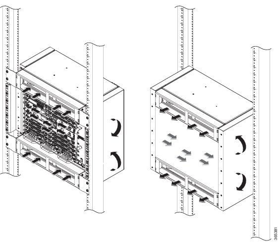
The fan trays maintain acceptable operating temperatures for the internal components by drawing in cool air through the vents, and circulating the air through the chassis.
The following guidelines will help you plan your equipment rack configuration:
- To ensure adequate air flow through the equipment rack, we recommend that you maintain a clearance of at least 80 mm on each side of the rack at all times.
- If airflow through the equipment rack and the routers that occupy it is blocked or restricted, or if the ambient air being drawn into the rack is too warm, an overtemperature condition can occur within the rack and the routers that occupy it.
- The site should also be as dust-free as possible. Dust tends to clog the router fans, reducing the flow of cooling air through the equipment rack and the routers that occupy it, thus increasing the risk of an overtemperature condition.
- Enclosed racks must have adequate ventilation. Ensure that the rack is not congested, because each router generates heat. An enclosed rack should have louvered sides and a fan to provide cooling air. Heat that is generated by the equipment near the bottom of the rack can be drawn upward into the intake ports of the equipment above.
- When mounting a chassis in an open rack, ensure that the rack frame does not block the side intakes and the exhaust fans.
- Avoid locating the Cisco NCS 4216 in a location in which the chassis air intake vents may draw in the exhaust air from adjacent equipment.
Air Flow Guidelines for Enclosed Rack Installation
To install a Cisco NCS 4216 in a 4-post enclosed cabinet, the front and rear doors of the cabinet must be removed or be perforated with a minimum of 65% open area (70% for 800mm racks).
If you are mounting the chassis in a 4-post enclosed cabinet, ensure that you have a minimum of 6 inches (15.24 cm) of clearance on each side of the chassis.
Floor Loading Considerations
Ensure that the floor under the rack supporting the Cisco NCS 4216 is capable of supporting the combined weight of the rack and all the other installed equipment.
To assess the weight of a fully configured Cisco NCS 4216, refer to the System Specifications section.
For additional information about floor loading requirements, consult GR-63-CORE, Network Equipment Building System (NEBS) Requirements: Physical Protection .
Site Power Guidelines
The Cisco NCS 4216 has specific power and cal wiring requirements. Adhering to these requirements ensures reliable operation of the system. Follow these precautions and recommendations when planning your site power for the Cisco NCS 4216:
- The redundant power option ensures that power to the chassis continues uninterrupted if one power supply fails or input power on one line fails.
- In systems configured with the redundant power option, connect each feed of the power supplies to a separate input power source. If you fail to do this, your system might be susceptible to total power failure due to a fault in the external wiring or a tripped circuit breaker.
- To prevent a loss of input power, be sure that the total maximum load on each circuit supplying the power supplies is within the current ratings of the wiring and the breakers.
- Check the power at your site before installation and periodically after installation to ensure that you are receiving clean power. Install a power conditioner if necessary.
- Provide proper grounding to avoid personal injury and damage to the equipment due to lightning striking power lines or due to power surges. The chassis ground must be attached to a central office or other interior ground system.
 Caution | This product requires short-circuit (overcurrent) protection, to be provided as part of the building installation. Install only in accordance with national and local wiring regulations. |
Note | The Cisco NCS 4216 installation must comply with all the applicable codes and is approved for use with copper conductors only. The ground bond fastening hardware should be of compatible material and preclude loosening, deterioration, and electrochemical corrosion of hardware and joined material. Attachment of the chassis ground to a central office or other interior ground system must be made with a 6 AWG gauge wire, copper ground conductor at a minimum. |
The maximum power draw of the Cisco NCS 4216 chassis and its configurable hardware components are listed in the following table. The maximum power draw values are not affected by the number of PSUs installed in the chassis.
|
Hardware component(s) |
Maximum power draw value |
|---|---|
|
Router chassis with 2 power supplies, 1 fan tray, and 1 RSP3C-400W |
(approx.) 500W |
|
NCS4216-RSP (active) |
230 W |
|
NCS4216-RSP (standby) |
219 W |
|
NCS4200-1T8LR-PS (8-port 1GE SFP + 1-port 10 GE interface module) |
29 W |
|
NCS4200-8T-PS (8-port 10 GE SFP interface module) |
57 W |
|
NCS4200-2Q-P (2-port 40 GE SFP interface module) |
53 W |
|
NCS4200-1H-PK (1-port 100 GE SFP interface module) |
62 W |
|
NCS4200-1T8S-10CS (OC-192 Interface Module with 8-port Low Rate CEM Interface Module (10G HO / 10G LO)) |
92 W |
|
NCS4200-48T1E1-CE (48 T1/E1 TDM Interface Module) |
35 W |
|
NCS4200-48T3E3-CE (48 T3/E3 TDM Interface Module) |
52 W |
cal Circuit Requirements
Each Cisco NCS 4216 requires a dedicated cal circuit. If you equip it with dual power feeds, provide a separate circuit for each power supply to avoid compromising the power redundancy feature.
The Cisco NCS 4216s can be powered by a DC source. Ensure that equipment grounding is present and observe the power strip ratings. Make sure that the total ampere rating of all products plugged into the power strip does not exceed 80% of the rating.
For more information about the Cisco NCS 4216 power supply, see the Power Supply Features section.
Site Cabling Guidelines
This section contains guidelines for wiring and cabling at your site. When preparing your site for network connections to the Cisco NCS 4216, consider the type of cable required for each component, and the cable limitations. Consider the distance limitations for signaling, electromagnetic interference (EMI), and connector compatibility. Possible cable types are fiber, thick or thin coaxial, foil twisted-pair, or unshielded twisted-pair cabling.
Also consider any additional interface equipment you need, such as transceivers, hubs, switches, modems, channel service units (CSU), or data service units (DSU).
Before you begin, read these important notes about cabling:
- The T1/E1 interface module for the Cisco NCS 4216 uses a high-density connector that requires the use of a T1/E1 interface cable and a customer-provided patch panel. For more information, see the Connecting T1/E1 cables section.
- Shielded cables must be used to connect to the DB-25 alarm connector on the fan tray in order to comply with FCC/EN55022/CISPR22 Class A emissions requirements. For information about the fan tray alarm port, see the Connecting the Fan Tray Alarm Port section.
Before you install the Cisco NCS 4216, have all the additional external equipment and cables on hand. For information about ordering, contact a Cisco customer service representative.
The extent of your network and the distances between the network interface connections depend in part on the following factors:
The distance and rate limits referenced in the following sections are the IEEE-recommended maximum speeds and distances for signaling purposes. Use this information as a guideline in planning your network connections >prior to installing the Cisco NCS 4216.
If wires exceed the recommended distances, or if wires pass between buildings, give special consideration to the effect of a lightning strike in your vicinity. The electromagnetic pulse caused by lightning or other high-energy phenomena can easily couple enough energy into unshielded conductors to destroy electronic devices. If you have had problems of this sort in the past, you may want to consult experts in cal surge suppression and shielding.
Asynchronous Terminal Connections
The RSP provides a console port to connect a terminal or computer for local console access. The port has an RJ45 connector and supports RS-232 asynchronous data with distance recommendations specified in the IEEE RS-232 standard.
Interference Considerations
When wires are run for any significant distance, there is a risk that stray signals will be induced on the wires as interference. If interference signals are strong, they can cause data errors or damage to the equipment.
The following sections describe sources of interference and how to minimize its effects on the Cisco NCS 4216 system.
Electromagnetic Interference
All equipment powered by DC current can propagate cal energy that can cause EMI and possibly affect the operation of other equipment. The typical sources of EMI are equipment power cords and power service cables from c utility companies.
Strong EMI can destroy the signal drivers and receivers in the Cisco NCS 4216 and even create an cal hazard by causing power surges through the power lines into installed equipment. These problems are rare but could be catastrophic.
To resolve these problems, you need specialized knowledge and equipment that could consume substantial time and money. However, you can ensure that you have a properly grounded and shielded cal environment, paying special attention to the need for cal surge suppression.
For information about the electrode magnetic compliance standards supported on the Cisco NCS 4216, see Regulatory Compliance and Safety Information for the Cisco NCS 4216.
Radio Frequency Interference
When electromagnetic fields act over a long distance, radio frequency interference (RFI) may be propagated. Building wiring can often act as an antenna, receiving the RFI signals and creating more EMI on the wiring.
If you use twisted-pair cable in your plant wiring with a good distribution of grounding conductors, the plant wiring is unlikely to emit radio interference. If you exceed the recommended distances, use a high-quality twisted-pair cable with one ground conductor for each data signal.
Rack-Mounting Guidelines
The sections provide guidelines for rack-mounting the Cisco NCS 4216
Precautions for Rack-Mounting
The following rack-mount guidelines are provided to ensure your safety:
- Do not move large racks by yourself. Due to the height and weight of a rack, a minimum of two people are required to accomplish this task.
- Ensure that the rack is level and stable before extending a component from the rack.
- Ensure that proper airflow is provided to the components in the rack.
- Do not step on or stand on any component or system when servicing other systems or components in a rack.
- When mounting the Cisco NCS 4216 in a partially filled rack, load the rack from the bottom to the top, with the heaviest component at the bottom of the rack.
- If the rack is provided with stabilizing devices, install the stabilizers before mounting or servicing the unit in the rack.
Rack Selection Guidelines
The Cisco NCS 4216 can be mounted in most two-post or four-post, 23-inch equipment racks that comply with the Electronic Industries Association (EIA) standard for equipment racks (EIA-310-D 23-inch). The rack must have at least two posts with mounting flanges to mount the chassis.
Caution | When mounting a chassis in any type of rack equipment, ensure that the inlet air to the chassis does not exceed 65 degrees C. |
The distance between the center lines of the mounting holes on the two mounting posts must be 18.31 inches ± 0.06 inch (46.50 cm ± 0.15 cm).
Consider installing the Cisco NCS 4216 in a rack with the following features:
- Network Equipment Building System (NEBS) compliant, 23-inch wide rack.
- EIA or European Telecommunications Standards Institute (ETSI) hole patterns in the mounting rails. The required mounting hardware is shipped with the Cisco NCS 4216. If the rack that you plan to install the system in has metric-threaded rails, you must provide your own metric-mounting hardware.
- Perforated top and open bottom for ventilation to prevent overheating.
- Leveling feet for stability.
Note | The Cisco NCS 4216 should not be installed in an enclosed rack because the chassis requires an unobstructed flow of cooling air to maintain acceptable operating temperatures for its internal components. Installing the router in any type of enclosed rack—even with the side doors removed —could disrupt the air flow, trap heat next to the chassis, and cause an overtemperature condition inside the router. If you use an enclosed rack, ensure that there are air vents on all sides of the rack and there is proper ventilation. To Install Air Plenum on 19-inch rack, select Flat Rack Post type. |
Equipment Rack Guidelines
The placement of the rack can affect personnel safety, system maintenance, and the system’s ability to operate within the environmental characteristics described in the System Specifications section. Choose a proper location for the Cisco NCS 4216 by following the guidelines.
Locating for Safety
If the Cisco NCS 4216 is the heaviest or the only piece of equipment in the rack, consider installing it at or near the bottom to ensure that the rack’s center of gravity is as low as possible.
For additional information about the proper placement of electronic equipment, consult the document GR-63-CORE, Network Equipment Building System (NEBS) Requirements: Physical Protection.
Locating for Easy Maintenance
Keep at least 3 feet of clear space at the front and back of the rack. This space ensures that you can remove the Cisco NCS 4216 components and perform routine maintenance and upgrades easily.
Avoid installing the Cisco NCS 4216 in a congested rack and consider how routing of cables from other pieces of equipment in the same rack could affect access to the router cards.
The sides of the chassis must remain unobstructed to ensure adequate airflow and prevent overheating inside the chassis.
Allow the following clearances for normal system maintenance:
- At the top of the chassis—At least 3 inches (7.6 cm)
- Sides of the chassis—3 to 4 ft (91.44 cm to 121.92 cm)
To avoid problems during installation and ongoing operations, follow these general precautions when you plan equipment locations and connections:
- Use the show environment all command regularly to check the internal system status. The environmental monitor continually checks the interior chassis environment; it provides warnings about high temperature and creates reports on other potentially dangerous occurrences. If warning messages are displayed, take immediate action to identify the cause, and correct the problem.
- Keep the Cisco NCS 4216 off the floor and out of areas that collect dust.
- Follow ESD-prevention procedures to avoid damage to equipment. Damage from static discharge can cause immediate or intermittent equipment failure.
Locating for Proper Airflow
Ensure that the Cisco NCS 4216 location has enough airflow to keep the system operating within the environmental characteristics and the air temperature is sufficient to compensate for the heat dissipated by the system. For more information, see the Air Flow Guidelines section.
Installation Checklist
To assist you with your installation and to provide a record of what was done by whom and when, photocopy the Cisco NCS 4216 Installation Checklist shown in the table below. Use this to record the completion and verification of each procedure. After the checklist is completed, place it in your Site Log along with the other records pertaining to your new Cisco router.
|
Task |
Verified By |
Date |
|---|---|---|
|
Date on which chassis received |
||
|
Chassis and all accessories unpacked |
||
|
Types and numbers of interfaces verified |
||
|
Safety recommendations and guidelines reviewed |
||
|
Installation Checklist copied |
||
|
Site Log established and background information entered |
||
|
Site power voltages verified |
||
|
Site environmental specifications verified |
||
|
Required passwords, IP addresses, device names, and so on, available |
||
|
Required tools available |
||
|
Network connection equipment available |
||
|
Cable-management brackets installed (optional, but recommended) |
||
|
DC power cables connected to DC sources and router |
||
|
Network interface cables and devices connected |
||
|
System power turned on |
||
|
System boot complete (STATUS LED is on) |
||
|
Shared port adapters are operational |
||
|
Correct software configuration displayed after system banner appears |
Creating a Site Log
The Site Log provides a record of all the actions related to installing and maintaining the router. Keep it in an accessible place near the chassis so that anyone who performs tasks has access to it.
Create the Site Log prior to the installation. (See Appendix A, Site Log and Manufactures section for more information on the Site Log as well as a sample Site Log that can be used to make copies.)
Receiving the Cisco NCS 4216
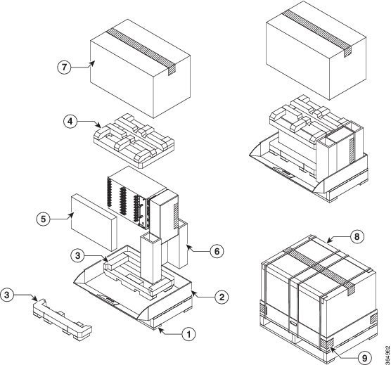
Each Cisco NCS 4216 chassis is shipped in a container. See the figure below.
|
1 |
Pallet |
6 |
Corrugated spacer |
|
2 |
Pellet deck board |
7 |
Carton |
|
3 |
Bottom foam |
8 |
Edge protector |
|
4 |
Top foam |
9 |
Tape |
|
5 |
Tray |
— |
Chassis-Lifting Guidelines
The chassis is not intended to be moved frequently. Before you install the system, ensure that your site is properly prepared so that you can avoid having to move the chassis later to accommodate power sources and network connections.
Each time you lift the chassis, follow these guidelines:
- Ensure that your footing is solid, and balance the weight of the chassis between your feet.
- Lift the chassis slowly; never move suddenly or twist your body as you lift.
- Keep your back straight and lift with your legs, not your back. If you must bend down to lift the chassis, bend at the knees, not at the waist, to reduce the strain on your back muscles.
- Do not remove installed components from the chassis.
- Always disconnect all external cables before lifting or moving the chassis.
To prevent personal injury or damage to the chassis, never attempt to lift or tilt the chassis using the handles on modules (such as power supplies, fans, or cards); these types of handles are not designed to support the weight of the unit. Lift the unit only by using handles that are an integral part of the chassis, or by grasping the chassis underneath its lower edge. Statement 163
Tools and Equipment
You need the following tools and equipment to install and upgrade the router and its components:
- ESD-preventive cord and wrist strap
- Antistatic mat or antistatic foam
- Number 1 and Number 2 Phillips-head screwdrivers
- Flat-blade screwdrivers: Small 3/16-inch (0.476 cm) and medium
1/4-inch (0.625 cm):
- To install or remove modules
- To remove the cover if you are upgrading the memory or other components
- #12-24 pan-head screws to secure the router to the equipment rack
- Cables for connecting to the WAN and LAN ports (depending on the configuration)
Note | For more information on cable specifications, see the Troubleshooting section. |
- Ethernet hub or switch or PC with a network interface card for connecting to the Ethernet ports
- Console terminal (an ASCII terminal or a PC running terminal emulation software) that is configured for 9600 baud, 8 data bits, no parity, and 2 stop bits
- Console cable for connecting to the console port
- (Optional) Modem for connecting to the auxiliary port for remote administrative access
- Auxiliary cable for connecting to the auxiliary port (you can supply this cable or order one)
- Ratcheting torque screwdriver with a Phillips head that exerts up to 30 pound-force per square inch (in-lb) of pressure
- Crimping tool as specified by the ground lug manufacturer
- 6 or 8 AWG copper wire for the power cord
- Wire-stripping tools for stripping both 6 AWG and 8 AWG wire
- Tape measure and level
- #2 Phillips Dynamometric screwdriver
- Medium slot-head screwdriver
- Small slot-head screwdriver
Warning | Only trained and qualified personnel should be allowed to install or replace this equipment. Statement 49 |
Unpacking and Verifying the Shipped Contents
When you receive your chassis, perform the following steps and use the Shipping Contents Checklist:
1. Inspect the box for any shipping damage. If there is obvious physical damage, contact your Cisco service representative.
2. Unpack the Cisco NCS 4216.
3. Perform a visual inspection of the chassis.
4. Use the table below to check the contents of the Cisco NCS 4216 shipping container. Do not discard the shipping container. You will need the container if you move or ship the Cisco NCS 4216 in the future.
DETAILED STEPS
What to Do Next
Component
Description
Chassis
Cisco NCS 4216 chassis (NCS4216-SA)
Fan tray (A907-FAN-E)
Power supplies (A900-PWR900-D2)
RSP (NCS4216-RSP)
Interface modules
Accessories kit (NCS4216-STRT-KIT)
Chassis rack-mount brackets (23-inch EIA)
Three sets of screws:
Eight cable-management brackets
One earth lug with two 10-32 screws.
1 RJ45 to RJ45 crossover cable
1 RJ45 to DB-9 (female) adapter
ANSI: #12-24 x 0.50 pan-head Phillips screws
ETSI: M6.0 x 20 pan-head Phillips screws
NCS4216-DOOR
Air Plenum Kit (A907-F2B-AIR)
One air plenum kit
ESD, wrist strap (disposable)
One disposable wrist strap (optional)
Documentation
Regulatory Compliance and Safety Information for the
Cisco NCS 4216
Optional equipment
Check the container for the following optional equipment:
Note | Most Cisco documentation is available online. Documentation that is shipped with your Cisco NCS 4216 includes the Regulatory Compliance and Safety Information for the Cisco NCS 4200 Series Aggregation Service Router document, and the Cisco NCS 4200 Series Aggregation Service Router Documentation Roadmap that contains information about the various documents that are available online and the links to them. |
 Feedback