Cisco NCS 4201 Features
The Cisco NCS 4201 family has the following capability:
- 1 RU form factor with fixed ENET interfaces (four 10GE and twenty-four 1GE SFP) and redundant modular power supplies (AC/DC).
The following table provides a snapshot of the number and type of supported ports:
|
1 GE Port |
10 GE Port |
Type of 1 GE Port |
Type of 10 GE Port |
Timing Ports |
|---|---|---|---|---|
|
24 |
4 |
24 Fiber |
Built in 4 SFP+ |
NA |
GE SFP Ports
The GE SFP ports support the following features:
- 100Base-FX and 1000Base-X SFP modules.
- Copper SFP modules
- Digital optical monitoring as specified by the SFP.
- Any mix of SFPs is supported unless specifically noted.
- Pause flow control as defined by the 802.3x standard.
- Frame size of 9216 bytes.
- Synchronous ENET operation that provides its recovered receive clock as an input clock source for the SETS as well as uses the system-wide reference clock to derive its transmit clock.
 Note |
Copper based SFPs do not support synchronous ENET operations. |
SFP+ Ports
The SFP+ ports support the following features:
- Digital optical monitoring as specified by the optical transceiver module.
- Any mix of SFPs is supported unless specifically noted.
- Pause flow control as defined by the 802.3x standard.
- Frame size of 9216 bytes.
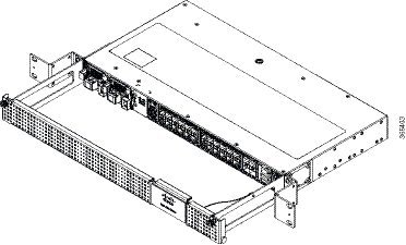
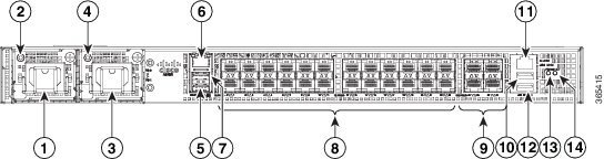
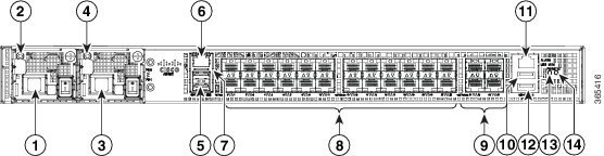
Front and Back Panel
The following figures display the Cisco NCS 4201 chassis views.
Note |
The Cisco NCS 4201 can also have AC and DC PSUs in the same chassis. |
|
1 |
Power Supply 0 (AC or DC) |
8 |
24x1GE SFP Fiber |
|
2 |
Power Supply 0 LED (AC or DC) |
9 |
4x10GE SFP+ |
|
3 |
Power Supply 1 (AC or DC) |
10 |
USB Memory port |
|
4 |
Power Supply 1 LED (AC or DC) |
11 |
Alarm port |
|
5 |
Console port (TIA/EIA-232F) |
12 |
USB Console port |
|
6 |
Management port |
13 |
Board power LED |
|
7 |
Auxiliary Console port |
14 |
System Status LED |
|
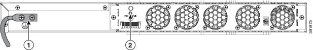
1 |
Grounding lugs |
2 |
Fan status LED |
Specifications
The table below describes the other features of Cisco NCS 4201 (AC and DC).
|
Specification |
Cisco NCS 4201 |
||
|---|---|---|---|
|
DimensionWidth x Depth x Height |
17.5 x 18.99 x 1.703 inches
|
||
|
Weight |
6.33 kg
|
||
|
Rack Unit |
One RU |
||
|
Airflow |
Front to back |
||
|
Cable access |
Front cable access |
||
|
Modularity |
None |
||
|
FRUs |
PSUs and fan tray |
||
|
Power Supply |
|||
|
Redundant |
Yes |
||
|
AC |
Yes |
||
|
Power Specification |
250 W Maximum |
||
|
DC |
Yes |
||
|
Power Specification |
250 W Maximum |
||
|
System Power Consumption |
145 W Maximum, 110 W Typical |
||
|
System Throughput |
64 Gbps/95 Mpps |
||
|
Heat Dissipation |
494.76 BTU/hr Maximum, 375.33 BTU/hr Typical |
||
|
Operating Temperature/Humidity |
–40º C to 70º C 5-95% RH |
||
|
Alarms |
|
||
|
TDM Support |
None |
||
|
Mounting option |
Front Z-bracket mount for 23 inches rack |
||
|
Port Configuration |
24x1G and 4x10G ports |
||
|
Port Numbering |
24x1G SFP (Fiber) – Port [0:23]4x10G SFP+ – Port [24:27] |
||
|
Combo Ports |
No combo ports |
||
|
LEDs |
System Status LEDData Port LEDsManagement Port LEDPSU LEDFan Tray LED |
||
|
Temperature Sensors |
Five temperature sensors for Board Two temperature sensors for each PSU |
||
|
Timing Interfaces |
1588v2 and SyncE feature supported |
External Interfaces
The Cisco NCS 4201 have these external physical interfaces on the front panel:
Network Interfaces
The network interfaces are provided through fixed ports.
- GE SFP ports (fiber)—supports 100/1000 modes
- 10GE SFP+—supports 10G mode.
External Alarm Inputs
The Cisco NCS 4201 supports four dry contact alarm inputs through an RJ-45 jack on the front panel.
- Normally Open—indicates that no current flows through the alarm circuit and the alarm is generated when the current is flowing.
Each alarm input can be provisioned as critical, major, or minor.
Management Interfaces
The Cisco NCS 4201 have the following management interfaces:
Management ENET Port
A single management copper ENET port supporting 10/100/1000Base-T operation is provided on the front panel. It uses a standard RJ-45 jack.
Note |
This is not a data plane port. |
Note |
This interface does not support Synchronous Ethernet Clocking. |
RS232-EIA Console Port
The RS232-EIA console port provides transmission (Tx), reception (Rx), and ground (Gnd).
Note |
The RS232-EIA console port is enabled only through the Cisco-designed cable adapter USB type A cable to RJ-45 adapter cable. To use this port, disable the flow control on the terminal. |
USB Console
A single USB 2.0 Type-A receptacle is provided on the front panel of the Cisco NCS 4201 for providing console access to ROMMON, Cisco IOS-XE and diagnostics. While it uses the Type-A connector, it operates as a USB peripheral only for connection to an external host computer. This interface requires the use of a Type-A to Type-A connector instead of a standard USB cable.
Note |
Use of the USB console is mutually exclusive of the RS232 console port. When the USB console cable is inserted in the USB console port, the RS232 console port is automatically disabled. This interface requires the use of a Type-A to Type-A USB cable. |
Note |
To use the USB console, you must download and install EXAR driver XR21x1410 on the external host computer. |
USB Mass Storage
A single USB 2.0 Type-A receptacle is provided on the front panel of the Cisco NCS 4201 for inserting external USB mass storage devices, such as standard USB flash drives. This interface is used to load images, load or store configurations, write logs, and so on. It supports operation up to 12Mbps.
Maximum memory supported in ROMmon is 8GB and in Cisco IOS is 16GB.
RS232 Auxiliary Console Port
The RS232 Aux console port provides transmission (Tx), reception (Rx), and ground (Gnd).
Note |
The RS232 Aux console port is enabled only through the Cisco-designed cable adapter from USB type A cable to RJ-45 adapter cable. To use this port flow control must be disabled. |
Note |
This is a debug-only port. it is recommended that this port be used by field service engineers only. |
Power Supply and Fans
The Cisco NCS 4201 support either AC or DC power supplies in a 1+1 redundant configuration. The PSUs are hot-swappable. Load is shared between PSUs when both the PSUs are inserted and powered-up. Status LED provided on both AC and DC PSU indicates the status and output condition.
|
Specification |
AC |
DC |
|---|---|---|
|
Voltage |
100 V – 240 V, 50/60Hz |
-48/-60 V or 24 V |
|
Current |
2.6 A through a standard C16 type receptacle |
5.5 A –48/–60 V 11 A –24 V through a two-position terminal block |
|
Input Power |
260 W (ASR-920-PWR-A) |
260 W (ASR-920-PWR-D) |
Note |
The Cisco NCS 4201 can have AC and DC PSUs in the same chassis. |
Note |
DC PSU can be switched on or off using a switch on the front panel of the DC PSU. |
Note |
For DC PSU, the UVP and OVP limits vary depending on the input voltage applied at power up: For -48/-60 V: UVP= -36 Vdc and OVP = -72 Vdc For 24 V: UVP =18 Vdc and OVP = 32 Vdc |
Note |
This product requires surge protection as part of the building installation. To comply with the Telcordia GR-1089 NEBS standard for electromagnetic compatibility and safety, an external surge protective device (SPD) is required at the AC power service equipment. |
Note |
For DC systems, if a surge of more than 1KV is expected, add an appropriate external surge protective device. |
The Cisco NCS 4201 has removable fan tray as part of the system. The fan tray is hot-swappable. The system is designed to operate at its maximum operating temperature of 70º C and at 65º C in case of failure of a single fan, for a maximum of four hours.
LED Indicators
This section describes the different types of LEDs and their behavior.
PWR and STAT LEDs
The PWR and STAT LEDs are available on the front panel. These LEDs provide power on the board (PWR) and overall chassis health (STAT) status. During power up state, these LEDs provide booting status and report errors.
Note |
The digital code signing functionality validates the integrity and authenticity of the ROMMON image before booting it. |
|
PWR LED State |
STAT LED state |
Indication |
Comment |
|---|---|---|---|
|
Amber |
Off |
Power in the system is all right and FPGA configuration is taking place. |
Permanent Amber/Off indicates FPGA configuration failure. |
|
Amber |
Red |
FPGA Image Validation Error. |
System is in unresponsive state. No console messages. |
|
Flashing Amber and Green alternatively |
Amber |
Upgrade FPGA image error, continuing with Golden FPGA image. |
— |
|
Flashing Amber and Green alternatively |
Off |
FPGA configuration successful and Digital code signing successfully validated FPGA image. Digital code signing passed the control to Microloader to boot ROMMON. |
— |
|
Flashing Amber and Green alternatively |
Red |
Digital code signing reported failure in ROMMON image validation. |
System is in unresponsive state. No console messages. |
|
Green |
Flashing Amber |
ZTP process has begun. |
Both LEDs turn Green once provisioning is complete. |
|
Green |
Off |
IOS-XE image is booting. |
|
|
Green |
Green |
Successfully booted and system is operating normally. |
— |
|
Green |
Amber |
A minor alarm or synchronization is in Holdover or free-running mode |
— |
|
Green |
Red |
A major or critical alarm (high temperature reported for any sensor) or multiple fan failure. |
— |
CPU Management Port LEDs
The LED for the 10/100/1000 Management port is integrated on the connector itself. There are two LEDs in the connector—the LED on the left indicates the Link/Activity status and the LED on the right is non-functional.
Note |
The CPU management port LED on the right is non-functional and hence doesn’t indicate any port status. |
|
LED |
LED State |
Indication |
|---|---|---|
|
Left |
Green |
Link up in 1000 Mbps |
|
Blinking Green |
Activity in 1000 Mbps |
|
|
Amber/Orange |
Link up in 100/10 Mbps |
|
|
Blinking Amber/Orange |
Activity in 100/10 Mbps |
|
|
Off |
Link down |
SFP LEDs
Each SFP port has an LED indicator. The LED is configured such that the up arrow indicates the port on the upside and the down arrow indicates the port on the downside.
|
LED |
LED State |
Indication |
|---|---|---|
|
Labeled same as the SFP port number |
Green |
Link up in 1000Base-X/100Base-FX |
|
Blinking Green |
Activity in 1000 Base-X/100Base-FX |
|
|
Yellow |
Fault/Error |
|
|
Off |
Link down |
SFP+ LEDs
Each SFP+ port has an LED indicator.
|
LED |
LED State |
Indication |
|---|---|---|
|
Labeled same as the SFP port number |
Green |
Link up in 10G |
|
Blinking Green |
Activity in 10G |
|
|
Yellow |
Fault/Error |
|
|
Off |
Link down |
Power Supply Unit LEDs
Each power supply unit has a corresponding LED on the front panel.
|
LED |
LED State |
Indication |
|---|---|---|
|
OK |
Green |
Power Supply is working and 12V output is alright. |
|
Red |
12V output failure (Either input not present or fault in the power supply unit). |
System–Interface LED Behavior
|
Event |
1G SFP Port LEDs |
|---|---|
|
ROMMON |
Off |
|
IOS Shut |
Off |
|
IOS No shut (cable disconnect) |
Yellow |
|
IOS No shut (cable connect) (media-type SFP) |
Green |
|
IOS No shut (cable connect) (media-type auto) |
Green |
|
Event |
10G Port LEDs |
Management Port LEDs (Link/Duplex) |
|---|---|---|
|
ROMMON (cable connect) |
Off |
Green/Green (1000 Mbps, Full Duplex) Orange/Green (100/10 Mbps, Full Duplex) |
|
ROMMON (cable disconnect) |
Off |
Off/Off |
|
IOS Shut |
Off |
Off/Off |
|
IOS No shut (cable disconnect) |
Orange |
Off/Off |
|
IOS No shut (cable connect) |
Green |
Green/Green in 1G mode Orange/Green in 100/10M mode |
Online Insertion and Removal
The Cisco NCS 4201 supports the following OIR operations:
- When an SFP is removed, there is no effect on traffic flowing on other ports.
- When an SFP is installed, the system initializes that port for operation based upon the current configuration. If the inserted SFP is incompatible with the current configuration for that port, the port does not become operational until the configuration is updated.
- Both power supplies are installed and active and the load may be shared between them or a single PSU could support the whole load. When a power supply is not working or the input cable is removed, the remaining power supply takes the entire load without disruption.
- When a fan tray is removed or replaced, there is no need to power down the chassis. However, when the fan tray is removed from chassis the chassis shuts down automatically after some time, depending on the ambient temperature. The time duration before the chassis shuts down is shown in the table below:
|
Sl. |
Inlet Ambient Temperature (ºCelsius) |
Shut Down Time (Minimum) |
|---|---|---|
|
1 |
–10 to –5 |
14 minutes |
|
2 |
–4 to 15 |
8 minutes |
|
3 |
16 to 29 |
6 minutes 30 seconds |
|
4 |
30 to 40 |
4 minutes 30 seconds |
|
5 |
41 to 44 |
3 minutes 20 seconds |
|
6 |
45 to 49 |
2 minutes 50 seconds |
|
7 |
50 to 54 |
2 minutes 10 seconds |
|
8 |
55 to 59 |
1 minutes 35 seconds |
|
9 |
60 to 64 |
1 minute |
|
10 |
65 and above |
35 seconds |
 Feedback