- Preface
- Introduction
- Creating and Analyzing Networks
- Viewing Network Reports
- Editing a Project
- Modeled Network Examples
- GUI Information and Shortcuts
- Cards and Pluggables
- Troubleshooting
- Third-Party DWDM Wavelength Interface Model
- Configuring CTP to Run on a Server
- Pay As You Grow Licensing
- OSMINE Layout Rules
- Index
Cisco Transport Planner DWDM Operations Guide, Software Release 10.6
Bias-Free Language
The documentation set for this product strives to use bias-free language. For the purposes of this documentation set, bias-free is defined as language that does not imply discrimination based on age, disability, gender, racial identity, ethnic identity, sexual orientation, socioeconomic status, and intersectionality. Exceptions may be present in the documentation due to language that is hardcoded in the user interfaces of the product software, language used based on RFP documentation, or language that is used by a referenced third-party product. Learn more about how Cisco is using Inclusive Language.
- Updated:
- January 26, 2017
Chapter: Creating and Analyzing Networks
- Creating a Project
- Adding Sites
- Adding Fiber Spans
- Creating an Optical Subnet
- Adding Notes to a Project
- Creating Traffic Subnet
- Creating a Demand
- Manual Regeneration
- Understanding Omnidirectional Functionality
- Understanding Colorless Functionality
- Understanding Colorless Omnidirectional Functionality
- Understanding Contentionless Functionality
- Creating a Protected Ring Demand
- Creating a ROADM Demand
- Creating Ethernet Aggregated Demands
- Creating TDM Aggregated Demands
- Creating a Regeneration Site
Creating and
Analyzing Networks
A project consists of a single network or multiple networks that you analyze and compare. In a project, you can have multiple copies of a single network with the same customer input data, but use different options in each to investigate multiple solutions.
- Creating a Project
- Adding Sites
- Adding Fiber Spans
- Creating an Optical Subnet
- Adding Notes to a Project
- Creating Traffic Subnet
- Creating a Demand
- Viewing Circuits in a Network
- Analyzing the Network
- Managing the Network Design
- Viewing a BoM
- Managing the Price List
- Importing Designs Created in the Sherpa Tool
- Bidirectional Communication with the Network Element
- Split ROADM
- Flex SMR with Inline DCU
- Connection Verification
Creating a Project
Use the following procedure to create a single network in a project. A new network is in the Design state. For more information about the different network states, see the Managing the Network Design.
 Note | All options that the Project Creation wizard sets can be changed as needed, except Measurement Units and ANSI/ETSI. |
| Step 1 | From the File menu, choose New or click New in the Start Page. The Project Creation wizard appears. | ||||||||||||||||||||||||||||||||||||||||||||||||||||||||||||||||||||||||||||||||||||||||||||||||||||||||||||||||||||||||||||||||||||||||||||||||||||||||||||||||||||||||||||||||||||||||||||||||||||||||||||||||||||||||||||||||||
| Step 2 | In the Project
Parameters area complete the following:
| ||||||||||||||||||||||||||||||||||||||||||||||||||||||||||||||||||||||||||||||||||||||||||||||||||||||||||||||||||||||||||||||||||||||||||||||||||||||||||||||||||||||||||||||||||||||||||||||||||||||||||||||||||||||||||||||||||
| Step 3 | Click Next.The Choose Platform area appears. | ||||||||||||||||||||||||||||||||||||||||||||||||||||||||||||||||||||||||||||||||||||||||||||||||||||||||||||||||||||||||||||||||||||||||||||||||||||||||||||||||||||||||||||||||||||||||||||||||||||||||||||||||||||||||||||||||||
| Step 4 | In the Choose Platform area, check the desired platform and click Next.The Choose Release area appears. | ||||||||||||||||||||||||||||||||||||||||||||||||||||||||||||||||||||||||||||||||||||||||||||||||||||||||||||||||||||||||||||||||||||||||||||||||||||||||||||||||||||||||||||||||||||||||||||||||||||||||||||||||||||||||||||||||||
| Step 5 | In the Choose Release area, check the desired software release for the network design and click Next.The Subnet Options area appears. To set a default software release, see the Setting the Default Software Release. | ||||||||||||||||||||||||||||||||||||||||||||||||||||||||||||||||||||||||||||||||||||||||||||||||||||||||||||||||||||||||||||||||||||||||||||||||||||||||||||||||||||||||||||||||||||||||||||||||||||||||||||||||||||||||||||||||||
| Step 6 | In the Subnet
Options area, complete the following:
| ||||||||||||||||||||||||||||||||||||||||||||||||||||||||||||||||||||||||||||||||||||||||||||||||||||||||||||||||||||||||||||||||||||||||||||||||||||||||||||||||||||||||||||||||||||||||||||||||||||||||||||||||||||||||||||||||||
| Step 7 | Click Next. | ||||||||||||||||||||||||||||||||||||||||||||||||||||||||||||||||||||||||||||||||||||||||||||||||||||||||||||||||||||||||||||||||||||||||||||||||||||||||||||||||||||||||||||||||||||||||||||||||||||||||||||||||||||||||||||||||||
| Step 8 | Complete one of
the following:
| ||||||||||||||||||||||||||||||||||||||||||||||||||||||||||||||||||||||||||||||||||||||||||||||||||||||||||||||||||||||||||||||||||||||||||||||||||||||||||||||||||||||||||||||||||||||||||||||||||||||||||||||||||||||||||||||||||
| Step 9 | In the Topology
area of the Network Creation wizard, choose one of the following options from
the Network-Topology drop-down list:
| ||||||||||||||||||||||||||||||||||||||||||||||||||||||||||||||||||||||||||||||||||||||||||||||||||||||||||||||||||||||||||||||||||||||||||||||||||||||||||||||||||||||||||||||||||||||||||||||||||||||||||||||||||||||||||||||||||
| Step 10 | To instruct Cisco Transport Planner to automatically create a traffic subnet associated with the created network, check the Create Traffic Subnet check box. Cisco Transport Planner creates (in addition to the Traffic_ALL) an additional traffic subnet (Traffic_Ring or Traffic_Linear) depending on the topology value you specify in the Network Creation wizard. | ||||||||||||||||||||||||||||||||||||||||||||||||||||||||||||||||||||||||||||||||||||||||||||||||||||||||||||||||||||||||||||||||||||||||||||||||||||||||||||||||||||||||||||||||||||||||||||||||||||||||||||||||||||||||||||||||||
| Step 11 | Click Next. The Configuration page appears. | ||||||||||||||||||||||||||||||||||||||||||||||||||||||||||||||||||||||||||||||||||||||||||||||||||||||||||||||||||||||||||||||||||||||||||||||||||||||||||||||||||||||||||||||||||||||||||||||||||||||||||||||||||||||||||||||||||
| Step 12 | Choose one of
the following options from the node type drop-down list:
| ||||||||||||||||||||||||||||||||||||||||||||||||||||||||||||||||||||||||||||||||||||||||||||||||||||||||||||||||||||||||||||||||||||||||||||||||||||||||||||||||||||||||||||||||||||||||||||||||||||||||||||||||||||||||||||||||||
| Step 13 | Enter the
number of sites in the fields displayed depending on the network topology
selected in Step 9.
The following options are
available:
The maximum number of locations where the optical service channel (OSC) can be terminated in a network is 150. The maximum number of add/drop locations (equipped with WSS, WXC, multiplexer/demultiplexer, or OADM cards) traversed by an optical circuit is by default limited to 40. However, this maximum limit can be customized to 150. | ||||||||||||||||||||||||||||||||||||||||||||||||||||||||||||||||||||||||||||||||||||||||||||||||||||||||||||||||||||||||||||||||||||||||||||||||||||||||||||||||||||||||||||||||||||||||||||||||||||||||||||||||||||||||||||||||||
| Step 14 | On the Site
Name and Topology area, choose the topology for each site from the drop-down
list.For multi-degree sites, choose the number of sides from the drop-down list
or see the
Adding Sites.
For corresponding options for NG-DWDM nodes, see Topology and Scalable Upto
Degree for NG-DWD table.
Available Site Topology
options are:
The site topology options displayed depend upon the restrictions listed in the following table.
The Topology and Scalable upto Degree options for NG-DWDM node are given in the following table.
| ||||||||||||||||||||||||||||||||||||||||||||||||||||||||||||||||||||||||||||||||||||||||||||||||||||||||||||||||||||||||||||||||||||||||||||||||||||||||||||||||||||||||||||||||||||||||||||||||||||||||||||||||||||||||||||||||||
| Step 15 | To enable the Split Node feature in any site, check the corresponding check box. The Split Node feature is available only for MSTP 15454 node type. | ||||||||||||||||||||||||||||||||||||||||||||||||||||||||||||||||||||||||||||||||||||||||||||||||||||||||||||||||||||||||||||||||||||||||||||||||||||||||||||||||||||||||||||||||||||||||||||||||||||||||||||||||||||||||||||||||||
| Step 16 | Click NextThe Options area appears. | ||||||||||||||||||||||||||||||||||||||||||||||||||||||||||||||||||||||||||||||||||||||||||||||||||||||||||||||||||||||||||||||||||||||||||||||||||||||||||||||||||||||||||||||||||||||||||||||||||||||||||||||||||||||||||||||||||
| Step 17 | The Options
area allows you to define C-band and L-band rules for the network design. In
the Options area complete the following:
| ||||||||||||||||||||||||||||||||||||||||||||||||||||||||||||||||||||||||||||||||||||||||||||||||||||||||||||||||||||||||||||||||||||||||||||||||||||||||||||||||||||||||||||||||||||||||||||||||||||||||||||||||||||||||||||||||||
| Step 18 | Click
Next.
The Site Management area appears. | ||||||||||||||||||||||||||||||||||||||||||||||||||||||||||||||||||||||||||||||||||||||||||||||||||||||||||||||||||||||||||||||||||||||||||||||||||||||||||||||||||||||||||||||||||||||||||||||||||||||||||||||||||||||||||||||||||
| Step 19 | In the Site
Management area, complete the following.
| ||||||||||||||||||||||||||||||||||||||||||||||||||||||||||||||||||||||||||||||||||||||||||||||||||||||||||||||||||||||||||||||||||||||||||||||||||||||||||||||||||||||||||||||||||||||||||||||||||||||||||||||||||||||||||||||||||
| Step 20 | Click Next.The Span Parameters area appears. | ||||||||||||||||||||||||||||||||||||||||||||||||||||||||||||||||||||||||||||||||||||||||||||||||||||||||||||||||||||||||||||||||||||||||||||||||||||||||||||||||||||||||||||||||||||||||||||||||||||||||||||||||||||||||||||||||||
| Step 21 | In the Span
Parameters area, complete the following.
| ||||||||||||||||||||||||||||||||||||||||||||||||||||||||||||||||||||||||||||||||||||||||||||||||||||||||||||||||||||||||||||||||||||||||||||||||||||||||||||||||||||||||||||||||||||||||||||||||||||||||||||||||||||||||||||||||||
| Step 22 | Click
Finish. CTP checks the validity of the fiber factor
values. If the fiber factor values are within the valid range (see the
following table), CTP creates a visual representation of the network. If the
values are out of range, CTP issues a warning, asking you to confirm the input
values.
|
Adding Sites
Use the following procedure to add new sites to an existing network. A site is a customer premise equipment (CPE) where any equipment can be co-located in a rack within a building. The Cisco Transport Planner supports up to 150 sites in a network. The number of racks and nodes in a site is independent of the number of sites in the network. The maximum number of locations where the OSC can be terminated in a network is 40. When the number of locations where the OSC is terminated exceeds the maximum supported value, the tool completes the design, but in the summary report an alarm is reported to indicate this situation. The maximum number of add/drop locations in a network is 40. The maximum number of add/drop locations (equipped with WSS, WXC, multiplexer/demultiplexer, or OADM) traversed by an optical circuit is limited to 40.
Note | Every new site added to a design is automatically configured as Multi-Shelf Integrated Switch with Same Shelf protection. To change this, you can edit the site properties after adding it to the network design. See the Editing Site Parameters. |
| Step 1 | Right-click the network folder in the Project Explorer pane and choose Expand from the shortcut menu. | ||
| Step 2 | Right-click the Sites folder and choose New Site from the shortcut menu. The Site Creation wizard appears. As an alternative, if sites already exist in the network design and you have the NtView Name tab open, click the Create a new site icon in the toolbar. For more information about the Cisco Transport Planner icons, see the GUI Information and Shortcuts. | ||
| Step 3 | Choose the type of node from the Node Type drop-down list. The options available are: | ||
| Step 4 | Choose the type
of interface from the
Select
line or terminal site drop-down list.
The
options available are:
| ||
| Step 5 | If you chose multi-degree in Step 4, choose the number of sides from the No of Sides drop-down list. The default option is two. | ||
| Step 6 | Enable NCS—Check this check box to use NCS PIDs for the selected site. For more information, see Table 3. | ||
| Step 7 | Click Finish. |
Adding Fiber Spans
Use the following procedure to manually add fiber spans between sites. A fiber span consists of a pair of fibers (one transmit and one receive) between two sites. A span is represented by a fiber duct in the NetViewName tab. Within a fiber duct, more than one fiber pair can exist.
Note | The number of fiber spans that each site can support is defined in the site properties. See the Adding Sites or the Editing Site Parameters. |
| Step 1 | In the NtView Name tab, click the Create a new duct icon in the toolbar. For more information about the Cisco Transport Planner icons, see the GUI Information and Shortcuts. | ||||
| Step 2 | Click one of the sites that you want to connect with a fiber span. This site becomes the source site for network analysis output, later. | ||||
| Step 3 | Click the
destination site. The New Duct dialog box appears. The selected site becomes
the destination site for network analysis output, later. For the first span,
the source site is set as A and the destination site is set as B. Cisco
Transport Planner automatically adjusts East and West for additional spans.
HYBRID 15454 ONS configuration cannot be connected to the 15454 MSTP
configuration. However, a network can have two clusters, one being the 15454
MSTP and the other being the 15216 hybrid without any connections between the
two.
| ||||
| Step 4 | Choose the
Connection Type:
| ||||
| Step 5 | Choose the
sides of the source and destination site to connect.
If you chose Line in Step 4, only the line sides are displayed here. If you chose Remote Add/Drop, the line side is displayed for the terminal site, while the pane of the other site lists the unconnected Remote Add/Drop ports of the site. |
Creating an Optical Subnet
An optical subnet is a collection of spans with certain associated, defined, common properties. You can define distinct optical subnets on the same network and can also set a list of associated properties on each of them.
The following properties are supported in an optical subnet:
- C-band Rules—Allows you to define rules for the C-band channels, the maximum per channel power, and the channel spacing for the design.
- L-band Rules—Allows you to define, for the L-band channels, the maximum per channel power, and the channel spacing for the design.
When you create a new project (see the Creating a Project), Cisco Transport Planner automatically creates an optical subnet associated to the network. At least one optical subnet (even if empty) must exist for each network in a project.
You can create an optical subnet using the Project Options (default) Optical Subnet property (Design Rules) values. To do this:
Adding Notes to a Project
Use the following procedure to add a note to any item in the Project Explorer pane. Each network has a Notes folder in the Project Explorer pane. After you have created a note, it appears in the Notes folder for that particular network.
| Step 1 | Right-click the desired item in the Project Explorer pane and choose Edit Note from the shortcut menu. | ||||||||
| Step 2 | In the Edit Note creation box, enter the desired text. | ||||||||
| Step 3 | To close the Edit Note creation box and to save the note, click the X in the upper right corner of the window. | ||||||||
| Step 4 | To view notes,
double-click the
Notes folder. The Notes window appears. The
following table lists the columns in the Notes window.
| ||||||||
| Step 5 | To close the Notes window, click the X in the upper right corner of the window. |
Creating Traffic Subnet
| Step 1 | In the Project Explorer pane, scroll down to Traffic Subnets. | ||
| Step 2 | Right-click
Traffic Subnets, and select
Create.
The Traffic Subnet Creation wizard appears. | ||
| Step 3 | Select the
Topology for the subnet from the drop-down list (Ring,
Linear, and
Mesh), then click
Next.
| ||
| Step 4 | Click Press to build new subnet. The Traffic Subnet Builder Wizard appears. | ||
| Step 5 | Select the ducts that should be a part of the subnet from the list displayed on the left handside, and click OK. This takes you back to the Traffic Subnet Creation Wizard. | ||
| Step 6 | Click Finish to complete the creation of the traffic subnet. The created subnet appears under Traffic Subnets in the Project Explorer pane. |
Creating a Demand
Cisco Transport Planner provides five types of service demands:
You can also create regeneration sites while creating a service demand.
CTP allows you to create property templates to design a set of property configurations for a demand. When you have a network that has similar sites, you can use these property templates to quickly and accurately set up common properties. For more information, see Property Template.
- Manual Regeneration
- Understanding Omnidirectional Functionality
- Understanding Colorless Functionality
- Understanding Colorless Omnidirectional Functionality
- Understanding Contentionless Functionality
- Creating a Protected Ring Demand
- Creating a ROADM Demand
- Creating Ethernet Aggregated Demands
- Creating TDM Aggregated Demands
- Creating a Regeneration Site
Manual Regeneration
In optical networks, as the fiber length increases, a loss in the signal ratio and power could occur due to attenuation and dispersion. A regenerator is required to recreate the weak and distorted optical signals through reamplification, regeneration, and retiming processes. The regenerators remove noise and distortion, convert the optical signal to an electrical signal, and then convert the signals back to optical signals (O-E-O conversion).
Cisco Transport Planner supports the creation of regeneration sites in the network. Regeneration is supported for the following demands:
- Point-to-point
- P-ring
- Ethernet Aggregated
- TDM Aggregated
The demand is displayed in the following manner:
Demand > Service > Trail > Section
- “Service” is the circuit through which traffic flows between nodes.
- “Trail” is the network section joining two traffic nodes. By default, a trail has only one section. The trail can be split in different regeneration sections.
- “Section” is a contiguous subset of the span.
A new section is added whenever a regeneration site is created. The sections can have different wavelengths based on availability. Regeneration can be performed using any two cards back-to-back (OTU2_XP, TXP, or MXP) or with a dedicated regenerator card.
Understanding Omnidirectional Functionality
The omnidirectional functionality on a side enables you to connect the side to a local multiplexer and demultiplexer that can add or drop traffic to or from any of the node directions. Omnidirectional traffic can be added or dropped only on the omnidirectional side.
Omnidirectional sides are different from standard add/drop sides in the following ways:
- Omnidirectional sides are internal sides that cannot be connected through fibers or ducts.
- Amplifiers on omnidirectional sides are placed between the 80-WXC-C card (bidirectional mode) and the Add/Drop (Mux/Demux) units.
- Raman amplification is
excluded on omnidirectional sides, as the amplification depends on the Raman
Amplified option on a duct.
Multi-degree sites that use the OXC functionality and are equipped with the following equipment can support omnidirectional sides:
Multi-degree OXC sites equipped with 40-WXC-C or 40-SMR2-C units can support both omnidirectional sides and the Omnidir Entry Point options. However, both options cannot be used on the same side.
For more information see the Modifying Site Properties.
Omnidirectional Demands
In all service demands (except ROADM demands), the value of the omnidirectional property is independent for each section or trail of a service.
You can perform operations at the trail level. The following are some examples:
- Terminate a working trail on the omnidirectional stage, and connect the protected trail to a standard add/drop stage.
- Terminate a trail on a line side and regenerate the trail in an intermediate omnidirectional side.
- Force both working and protected trails (or consecutive trails in the case of a P-Ring demand) to terminate on the same omnidirectional side. By default, traffic from all demands (except ROADM demands) terminates on two different omnidirectional sides.
The omnidirectional property is available for the source and destination of each section of a service trail. A section terminating on an omnidirectional side can be routed in all possible directions. If multiple omnidirectional sides are available for a site, you can force the section to terminate on a specific side.
Understanding Colorless Functionality
The colorless property enables tuning of channel wavelengths without changing the optical interface of the port. A colorless side is connected to two 80-WXC-C cards configured as a multiplexer and demultiplexer.
A colorless stage is available at the local add/drop stage on line, terminal, or multi-degree sites. In line and terminal sites, you can implement colorless sides using the following configurations:
- Line or terminal ROADM site with 80-WXC-C cards
Note | For line sites, you must have 80-WXC-C cards on both sides even when only one of the ports is forced as colorless. |
- Line or terminal sites equipped with 40-SMR1-C
- Line or terminal sites equipped with 40-SMR2-C
In multi-degree sites you can implement colorless sides through a node having OXC functionality and are equipped with the following:
- 40-WXC-C/MESH-PP-4
- 40-WXC-C/MESH-PP-8
- 80-WXC-C/MESH-PP-4
- 80-WXC-C/MESH-PP-8
- 40-SMR2-C
Colorless Demands
In all service demands (except ROADM) the colorless property is available separately for each trail and section of a service demand.For example, in a P-ring demand you can terminate one trail on a colorless mux/demux stage and connect the other trail to a standard (colored) mux/demux stage.Colorless sections must be associated to an 80-WXC-C colorless port and can be terminated on sides having colorless add/drop ports to achieve full wavelength tuning capability on fixed physical ports.
Understanding Colorless Omnidirectional Functionality
A colorless and omnidirectional side is connected to a multiplexer (80-WXC-C card) and demultiplexer (80-WXC-C card) that can add or drop traffic to or from any of the node directions. You can define an omnidirectional colorless side by adding one or more colorless ports to an omnidirectional side.
In all service demands (except ROADM), you can configure colorless termination points as omnidirectional, to achieve full routing capability for all possible wavelengths.
Note | In a 50GHz design, an omnidirectional demand can be dropped only on a colorless omnidirectional side. |
Understanding Contentionless Functionality
The contentionless functionality on a site refers to the contentionless add/drop ability of an N-degree ROADM node to accommodate N wavelengths of the same frequency from a single add/drop device. For a ROADM to be contentionless, the number of drop units should be equal to ROADM degrees.
Multi-degree sites that use the OXC functionality and are equipped with the following equipment can support contentionless sides:
– 12-AD-CCOFS
– 16-AD-CCOFS
For more information see the Modifying Site Properties.
Creating a Point-to-Point Demand
Use the following procedure to add a point-to-point traffic demand:
| Step 1 | In the NtView Name tab, click the Create new Point-to-Point demand icon in the toolbar. For more information about the Cisco Transport Planner icons, see the GUI Information and Shortcuts. | ||||||
| Step 2 | Click the source site of the demand. | ||||||
| Step 3 | Click the destination site of the demand. The Point to Point Demand Creation wizard appears. | ||||||
| Step 4 | From the drop-down list, select Traffic Subnet ALL or any of the previously created traffic subnets to which this service demand should be part of, and proceed to Step 5. If you wish to create a new traffic subnet see the Creating Traffic Subnet. | ||||||
| Step 5 | Click Next. | ||||||
| Step 6 | On the General
Parameters page, complete the following:
| ||||||
| Step 7 | Click Next. The Platform Parameters page appears. | ||||||
| Step 8 | On the Platform
Parameters page, complete the following in the Platform area:
| ||||||
| Step 9 | In the Platform
Parameters page, complete the following fields in the Interface/Card Type area.
The options available are based on the service type selected in Step 6.
| ||||||
| Step 10 | In the Client
Interface area, define the client interface type for the source (SR, ZR, ER, or
LR) and destination (EW, SW, or LW) from the Source and Destination drop-down
list. This option is available for transponder and muxponder interfaces that
have pluggable client interfaces that depend on the selected service type and
card type.
| ||||||
| Step 11 | Click
Finish. The Demand Editor dialog box appears listing
the present and forecast channels.
The demand appears in the NtView name tab and in the Project Explorer pane in the Service Demands > Point To Point folders. A demand is a solid line when selected and a dotted line when not selected. The line has a number above it that indicates the number of channels that are present. The following figure shows a selected point-to-point demand with five channels between sites 1 and 2. 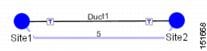 | ||||||
| Step 12 | To add a new service, click the Add new service icon in the toolbar. A new row appears. Complete the parameters for the new channel. | ||||||
| Step 13 | To delete an existing channel, select the row and click the Delete service icon in the toolbar. | ||||||
| Step 14 | To set path
constraints, click the
Path
Constraints Editor
icon in the toolbar and complete the following as
required:
Click OK to save the changes and Cancel to close the dialog box without saving the changes. | ||||||
| Step 15 | This icon is available only at the trail level of the service demand. | ||||||
| Step 16 | To add a regeneration site, click the Regeneration... icon in the toolbar. The Regeneration editor appears. The regeneration site can be created only at the trail level. For more information, see the Creating a Regeneration Site. | ||||||
| Step 17 | Click
OK to save the changes to the channels and close the
Demand editor dialog box, or
Cancel to close the dialog box without saving the
changes.
|
Creating a Protected Ring Demand
Use the following procedure to create a P-ring traffic demand.
| Step 1 | Create a ring network using either the procedures in Creating a Project or by manually placing sites into a ring configuration. | ||
| Step 2 | In the Native Net# tab, click the Create new P-Ring demand icon in the toolbar. The P-Ring Creation wizard appears. For more information about the Cisco Transport Planner icons, see Appendix A, “GUI Information and Shortcuts.” | ||
| Step 3 | For each network, the tool automatically creates, a default subnet that exactly matches the overall network topology. This cannot be deleted. From the drop-down list, select any previously created traffic subnet with a ring topology that this circuit should be part of and proceed to Step 4. If you wish to create a new traffic subnet see the Creating Traffic Subnet. | ||
| Step 4 | On the General
Parameters page, complete the following:
| ||
| Step 5 | Click Next. | ||
| Step 6 | On the Sites Selection page, in the Protection Sites area, press Ctrl and click the sites that you want to add to the P-ring. A P-ring requires at least two sites. Click the right arrow button. To remove a site added to the list, click the site and click the left arrow button. In the Optical Bypass area, press Ctrl and click the sites that you want to add to the P-ring. Click the right arrow button. To remove a site added to the list, click the site and click the left arrow button. | ||
| Step 7 | Click Next. The WDM Client Selection page appears. | ||
| Step 8 | On the WDM
Client Selection page, enter the following Platform Parameters:
| ||
| Step 9 | Complete the
following in the Interface/Card Type area. The options available are based on
the service type selected in Step 4.
In the Client Interface area, define the client interface type for the source (SR, ZR, ER, or LR) and destination (EW, SW, or LW) from the Source and Destination drop-down list. This option is available for transponder and muxponder interfaces that have pluggable client interfaces that depend on the selected service type and card type.
| ||
| Step 10 | Click
Finish. The Demand Editor dialog box appears.
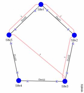
The demand appears in the NtView name tab and in the Project Explorer pane in the Service Demands > P-Rings folders. A demand is a solid line when selected and a dotted line when not selected. The line has a number above it that indicates the number of channels present. The below figure shows a selected one-channel P-ring between sites 1, 2, 3, and 5 with an optical bypass of site 4. | ||
| Step 11 | To add a new service, click the Add new service icon in the toolbar. A new row appears. Complete the parameters for the new channel. | ||
| Step 12 | To delete an existing channel, select the row and click the Delete service icon in the toolbar. | ||
| Step 13 | To add a regeneration site, click the Regeneration... icon in the toolbar. The Regeneration editor appears. The regeneration site can be created only at the trail level. For more information, see the Creating a Regeneration Site. | ||
| Step 14 | Click
OK to save the changes to the channels and close the
Demand Editor dialog box, or
Cancel to close the dialog box without saving the
changes.
 |
Creating a ROADM Demand
Use the following procedure to create ROADM traffic groups and demands:
| Step 1 | In the Project Explorer pane, under Nets, right-click the ROADM folder and choose New ROADM Group. The ROADM Group Creation wizard appears. | ||
| Step 2 | Select the desired traffic subnet from the Traffic Subnet field. You can create a new traffic subnet if desired using the Creating Traffic Subnet. | ||
| Step 3 | Enter the ROADM traffic group name in the Group Name field. | ||
| Step 4 | Check the desired sites. | ||
| Step 5 | Click Finish. The new ROADM traffic group appears under the ROADM folder in the Project Explorer pane. | ||
| Step 6 | Right-click the new ROADM traffic group and choose Create new ROADM demand from the shortcut menu. The Create ROADM Demand dialog box appears. | ||
| Step 7 | (Optional) If you copied properties of an existing ROADM demand, click Use Template to use the properties of the copied ROADM demand. | ||
| Step 8 | Enter a name for the demand in the Demand Name field. | ||
| Step 9 | Select a
traffic pattern type (Hub, Meshed, or Ring) from the Traffic Type drop-down
list:
| ||
| Step 10 | Select a routing strategy from the Routing Strategy drop-down list: Protected, Unprotected Minimum Hop, Unprotected Optimum Path, or Unprotected Subnet. If you chose Unprotected Subnet, continue with the next step; otherwise proceed to Step 12. | ||
| Step 11 | If you chose Unprotected Subnet, choose the starting site and the direction the ring must be traversed from the drop-down lists. | ||
| Step 12 | In the Service Types list, check the boxes for one or more client service types for the ROADM demand. The client interfaces that support each service type appear in the table to the right of the Service Types list. For a list of line cards supported for specific service types, see the Service Support. | ||
| Step 13 | Check the
OmniDirection check box to enable the omnidirectional property for the ROADM
demand.
| ||
| Step 14 | Check the
Colorless check box to enable the colorless property for the ROADM demand.
| ||
| Step 15 | Check the Contentionless check box to enable the contentionless property for the ROADM demand. | ||
| Step 16 | To further
define the client interfaces, complete the following options for each client
interface listed in the table. Check boxes in gray are not available for
selection.
You can select more than one client interface to support the same service type. By default, Cisco Transport Planner checks the best client interface to support each service. | ||
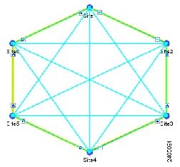
| Step 17 | Click OK to
create the demand. The following figure shows an example of ROADM Demand.
 | ||
| Step 18 | Copy ROADM
demand properties. The following properties are copied:
These properties can be used as a template while creating a new ROADM demand or editing an existing one. To copy the properties, select the ROADM demand, right-click, and choose the Copy Properties option. When the ROADM demand properties are copied, the Use Template button is enabled in the Create ROADM Demand and Edit ROADM Demand dialog boxes.
| ||
| Step 19 | Analyse the
network.
Click the Analyze Network icon in the toolbar. | ||
| Step 20 | Finalize the
Any-to-Any demand. Perform one of the following:
To finalize Any-to-Any demand in design-analyzed state, complete Step 21. To finalize Any-to-Any demand in upgrade state, complete Step 22. | ||
| Step 21 | To finalize
Any-to-Any demand in design-analyzed state, complete the following steps:
| ||
| Step 22 | To finalize
Any-to-Any demand in upgrade state, complete the following steps:
| ||
| Step 23 | To edit any
Any-to-Any finalized demand, complete the following steps:
Click the Mgmt Tree tab and right-click the analyzed network. Choose A2A Finalized Circuits from the drop-down list. The A2A Finalized Circuits tab appears. Select any Any-to-Any Finalized demand and click Edit on the toolbar or double-click the demand in The A2A Finalized Circuits tab. CTP prompts to unlock the network. Choose Yes to open the demand editor. The network is set to Any-to-Any Finalization mode on unlocking the demand. Modify as required and click OK to close the demand editor.
| ||
| Step 24 | Finalize the demand again for the changes to be reflected in the A2A Finalized Circuits report. | ||
| Step 25 | To delete any
Any-to-Any finalized demand, complete the following steps:
|
Creating Ethernet Aggregated Demands
An Ethernet aggregated demand is a collection of low-rate Gigabit Ethernet/10Gigabit Ethernet services that can be aggregated on a single 10-Gbps wavelength division multiplexing (WDM) trunk. This demand is supported only by the GE_XP, 10GE_XP, GE_EXP, and 10GE_EXP cards when configured as an L2-Switch.
The Ethernet Aggregation Creation wizard allows you to:
- Create one WDM transport channel at a time over a predefined traffic subnet.
- Specify the wavelength to be used for the channel, and define a list of locations with add/drop VLAN circuit capability.
- Create a set of desired VLAN circuits on this WDM transport channel.
- The check functionality generates a report showing for each section of the subnet where the WDM transport channel is over allocated and then perform corrective action when required.
- The clone functionality creates an identical copy of the current WDM transport channel with the same add/drop sites and WDM channel configuration parameters. You can then start filling this channel with the desired circuits.
Use the following procedure to create Ethernet aggregated demands:
| Step 1 | In the NtView name tab, click the Create new AggregatedEthernet demand icon in the toolbar. For more information about Cisco Transport Planner icons, see GUI Information and Shortcuts. The EthernetAggr Creation wizard appears. |
| Step 2 | Choose the desired traffic subnet from the Traffic Subnet drop-down list. You can create a new traffic subnet if desired (see Creating Traffic Subnet). |
| Step 3 | Click Next. The General Parameters page appears. |
| Step 4 | In the General
Parameters pane, enter values in the following fields:
|
| Step 5 | Click Next. |
| Step 6 | In the Sites
selection pane, complete the following tasks:
|
| Step 7 | In the Node
Configuration selection pane, enter values for the following options:
|
| Step 8 | Click Finish. The name Demand window appears. |
| Step 9 | Click Close. |
| Step 10 | To add a circuit, right-click the Ethernet Demand in the Project Explorer pane and choose New point to point request. The New Request window appears. |
| Step 11 | The
New
Request window contains four areas of information: Quantity,
General, Src, and Dest.
Quantity Area Quantity—Enter the number of circuits to be created. General Area
Src Area
Working sub-area
Protected sub-area These fields are enabled only if client protection is enabled in the Client Protection field.
Dest Area
Working sub-area
Protected sub-area These fields are enabled only if the client protection is enabled in the Client Protection field.
|
| Step 12 | Click OK. |
| Step 13 | The
Traffic tab displays the following details about the
circuit:
|
| Step 14 | If you want to clone this demand, click the Clone button in the left corner of the screen. A new demand, which is a copy of this demand, is created and appears in the Project Explorer pane. |
| Step 15 | Click the Check tab in the left corner of the window to generate a report showing the circuit path in the WDM traffic channel and to check any over-allocation of bandwidth. The Report tab displays, in a row, each of the sites on the subnet, and each span in between. |
| Step 16 | The
Traffic Result tab displays the following:
|
| Step 17 | To add a regeneration site, click the Regeneration... icon in the toolbar of the DWDM channel tab. The Regeneration Editor appears. The regeneration site can be created only at the trail level. For more information, see the Creating a Regeneration Site. |
| Step 18 | Click Close. To edit circuits, see the Editing an Ethernet Aggregated Demand. |
Creating TDM Aggregated Demands
A TDM aggregated demand is a collection of low-rate SONET and Gigabit Ethernet services that is aggregated on a single 10-G WDM trunk. The TDM aggregated demand is a specific service demand that is carried only by the ADM-10G card.
The TDM Aggr Creation wizard allows you to:
- Create one WDM transport channel at a time over a predefined traffic subnet
- Specify the wavelength to be used for the channel, and define a list of locations with add/drop STS circuit capability.
- Create a set of STS circuits on this WDM transport channel to pass traffic.
- The check functionality generates a report showing, for each section of the subnet, where the WDM transport channel is over allocated and then perform, when required, the corrective action.
The total amount of bandwidth used by all the defined circuits in each section of the WDM transport channel cannot exceed the maximum channel capacity of STS-192c. Sections exceeding the maximum capacity are colored red in the report. Demands that fail the check are flagged as invalid demands and the Analyzer stops.
The clone functionality allows you to create an empty copy of the current WDM transport channel, with the same add/drop sites and WDM channel configuration parameters. You can then start filling this channel with the desired circuits.
Use the following procedure to create TDM aggregated demands:
| Step 1 | In the NtView name tab, click the Create new TDM Aggregated demand icon in the toolbar. For more information about CTP icons, see the GUI Information and Shortcuts.The TDMAggr wizard appears. |
| Step 2 | Select the desired traffic subnet from the Traffic Subnet drop-down list. You can create a new traffic subnet if desired using (see the Creating Traffic Subnet). |
| Step 3 | Click Next. The General Parameters page appears. |
| Step 4 | In the General
Parameters pane, complete the following tasks:
|
| Step 5 | Click Next. |
| Step 6 | In Sites
selection pane, complete the following tasks:
|
| Step 7 | In the Node
Configuration selection pane, complete the following tasks:
|
| Step 8 | Click Finish. The name Demand window appears. |
| Step 9 | Click Close. |
| Step 10 | To add a circuit, right-click the Ethernet Demand in the Project Explorer pane and choose New point to point request. The New Request window appears. |
| Step 11 | The
New
Request window contains four areas of information: Quantity,
General, Src, and Dest.
Quantity Area Quantity—Enter the number of circuits to be created. General Area
Src Area
The Src area contains Working and Protected sub-areas. Working sub area
Protected sub area The following fields are available only if client protection is enabled:
Dest Area
Working sub area
Protected sub-area |
| Step 12 | Click OK. |
| Step 13 | If you want to clone this demand, click the Clone button in the left corner of the screen. A new demand, which is a copy of this demand, is created and appears in the Project Explorer pane. |
| Step 14 | Click the Check tab on the left corner of the window to generate a report showing the circuit path in the WDM traffic channel and to check any over-allocation of bandwidth. The report shows, in a row, each of the sites on the subnet, and each span in between. |
| Step 15 | To add a regeneration site, click the Regeneration... icon in the toolbar of the DWDM channel tab. The Regeneration Editor appears. The regeneration site can be created only at the trail level. For more information, see the Creating a Regeneration Site. |
| Step 16 | Click Close. To edit circuits, see the Editing a TDM Aggregated Demand. |
Creating a Regeneration Site
A regeneration site is required when the optical communications link has to span long distances. The optical signal has to be regenerated when the optical signal-to-noise ratio (OSNR) goes beyond a critical limit. After a network is analyzed, the Optical Results highlights if any site requires regeneration. For more information about optical results, see the Viewing Optical Results.
Use the following procedure to create a regeneration site in the network.
Note | A regeneration site cannot be a site with the functionality as OLA, OSC, pass-through, or hub. |
Note | The Regeneration... icon is active only when you select a trail in the Demand Editor. |
| Step 1 | In the Demand Editor, click the Regeneration... icon in the toolbar. The Regeneration Editor appears. For more information about Cisco Transport Planner icons, see GUI Information and Shortcuts. | ||||
| Step 2 | In the
Available Sites area, choose the site and click the down arrow icon. To remove
a site added to the Regeneration Sites list, choose the site and click the up
arrow icon.
| ||||
| Step 3 | To sort the regeneration sites in the list, use the up and down arrow icons located on the left. | ||||
| Step 4 | If you chose a
source or destination card for a regeneration site, choose the card type for
the site from the drop-down list. The regeneration cards that are compatible
with the source and destination cards are displayed in the interface.
| ||||
| Step 5 | Colorless—
Choose an option from the drop-down list. Colorless traffic demands are
terminated at colorless add/drop ports, so that, these demands can be tuned in
all possible wavelengths without changing the optical interface of the port.
| ||||
| Step 6 | Omnidir Src Side, Omnidir Dest Side— Choose an option to enable omnidirectional functionality on a source or destination side. An omnidirectional side allows routing of the added and dropped traffic in all the possible directions associated to Line sides. | ||||
| Step 7 | Click
OK.
|
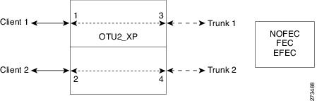
Configurations for OTU2_XP
The OTU2_XP card operates in six different configurations as shown in the following table:
|
Configuration |
Card listed as |
Port 1 |
Port 2 |
Port 3 |
Port 4 |
||
|---|---|---|---|---|---|---|---|
|
Dual Transponder (2 x 10G transponder) |
OTU2-XP-Txp mode |
Client port 1 |
Client port 2 |
Trunk port 1 |
Trunk port 2 |
||
|
Dual Regenerator (2 x 10G standard regenerator with enhanced FEC [E-FEC] only on one port) |
OTU2-XP- Regen mode |
Trunk port 1 |
Trunk port 2 |
Trunk port 1 |
Trunk port 2 |
||
|
Single Regenerator (1 x 10G E-FEC regenerator with E-FEC on two ports)) |
OTU2-XP- Single Regen mode |
Not used |
Not used |
Trunk port |
Trunk port |
||
|
10 GE LAN Phy to WAN Phy |
OTU2-XP-Txp modeMixed modeSplitter mode |
Client port |
Client port in transponder or trunk port in regenerator configuration |
Trunk port
|
Trunk port in transponder or regenerator configuration. |
||
|
Protected Transponder (1 x 10G splitter protected transponder) |
OTU2-XP- Splitter mode |
Client port |
Not used |
Trunk port (working) |
Trunk port (protect) |
||
|
Mixed Mode (1 x 10G transponder and 1 x 10G standard regenerator) |
OTU2-XP- Mixed mode |
Client port |
Trunk port 4 without FEC or with FEC |
Trunk port 1 without FEC or with FEC or E-FEC |
Trunk port 2 without FEC or with FEC or E-FEC |
- Dual Transponder (OTU2-XP-Txp)
- Dual Regenerator (OTU2-XP-Regen)
- Single Regenerator (OTU2-XP- Single Regen)
- Protected Transponder (OTU2-XP- Splitter)
- Mixed Mode (OTU2-XP- Mixed)
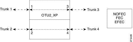
Dual Transponder (OTU2-XP-Txp)
You can configure the OTU2_XP card as a dual transponder as shown in the below figure. When configured as a dual transponder (OTU2-XP-Txp), the card supports two completely independent bidirectional 10-Gbps services. Port 1 and Port 2 support traffic from or to port 3 and port 4, respectively. Both paths are completely independent and can support different services. G.709 wrapping or unwrapping and FEC correction capability can be independently activated on each path.
You can assign one the following service types as the client:
You can set one of the following trunk modes on both trunks for any of the service types:
Dual Regenerator (OTU2-XP-Regen)
You can configure the OTU2_XP card as a dual regenerator as shown in the below figure. When configured as a dual regenerator (OTU2-XP-Regen), the unit regenerates two completely independent bidirectional 10-Gbps signal paths (similar to the OTU2-XP-Txp configuration). In this configuration, all four ports support DWDM XFPs. You can also independently set G.709 framing and FEC capability for all four ports. You can enable E-FEC encoding only on ports 3 and 4.
You can use the following combinations of trunk modes according to the framing of the service to be regenerated:
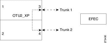
Single Regenerator (OTU2-XP- Single Regen)
You can configure the OTU2_XP card as a single regenerator as shown in the below figure. When configured as a single regenerator (OTU2-XP- Single Regen), the card regenerates only one bidirectional 10-Gbps signal path. The ports 3 and 4 support DWDM XFPs and G.709 framing as well as E-FEC.
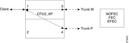
Protected Transponder (OTU2-XP- Splitter)
You can configure the OTU2_XP card as a protected transponder as shown in the below figure. When configured as a protected transponder (OTU2-XP- Splitter), the card implements the fiber-switched protection. In this configuration, the client service on port 1 is transmitted to ports 3 and 4 and then on to both trunks. Only one signal received from the two trunks on ports 3 and 4 is transmitted to port 1 (the signal from the other port is only monitored). After detecting a failure on one trunk, the unit automatically switches on the other port, which restores the signal on port 1. In protected-transponder configurations, port 2 is always disabled.
You can set one of the following service type for the client port:
You can set one of the following trunk modes on both trunks for any of the service types:
- No FEC
- FEC
- E-FEC
Mixed Mode (OTU2-XP- Mixed)
You can configure the OTU2_XP card in mixed mode (See Mixed-Mode Configuration figure). When configured in mixed mode (OTU2-XP- Mixed), the card is a regenerator on one set of the ports and a transponder on the other set. The two sets are completely independent and can be configured to transmit or regenerate different services. You can independently set G.709 framing and FEC capability on each trunk port, but ports 1 and 2 cannot have E-FEC encoding.
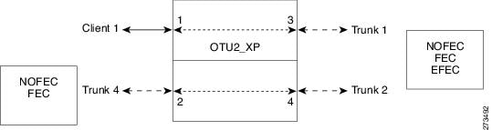
You can swap the configuration of the two sets, that is, ports 1 to 3 set as the regenerator and ports 2 and 4 as the transponder.
You can set one of the following service types for the client port:
You can set one of the following trunk modes on all the trunks for all service types:
- No FEC (all)
- FEC (all)
- E-FEC (only to ports 3 and 4)
CTP does not automatically select mixed mode for OTU2_XP cards. You need to select mixed mode for an OTU2_XP card to force it.
Note | The FI and FC demands are not supported on port 2 as a source when the LAN-WAN traffic is fed as a source on port 1. |
For further information on the OTU2_XP card, refer to the Cisco ONS 15454 DWDM Configuration Guide, Release 9.6.x.
Viewing Circuits in a Network
You can view all the circuits that have been created in any of the Service Demands folders in the Traffic tab of the Net1 tab.
The following columns are displayed:
- SA—Indicates the system alarms that affect the circuit. This indication is available only after the network is analysed.
- AL— Indicates the optical alarms that affect the circuit.This indication is available only after the network is analysed.
- F—Indicates if the demand will be needed in the future.
- Demand —Displays the name of the demand.
- Group—Displays the demand group to which the circuit belongs.
- Label —Displays the label of the circuit.
- TMSubnet—Displays the name of the traffic subnet in which the circuit is defined.
- SrvType— Displays the service type value.
- Sites—Lists the add/drop site.
- Card/TrunkType—Displays the card type and trunk type.
- Protection type— Displays the protection type of the demand.
- Wavelength —Displays the assigned wavelength.
- Encryption—Displays whether the traffic is encrypted or not.
You can edit the circuits for any demand by double-clicking the circuit or by choosing the circuit and clicking the Edit button in the toolbar.
Use any one of the following options to group and order the circuits:
- Type\Demand\Group— The circuits are first grouped and ordered by demand name. Each set of circuits with the same demand name is then ordered by the group name.
- SrvType\Type\group—The circuits are first grouped and ordered by service type. Each set of circuits with the same service type is then ordered by the group name.
Note | You can also select a set of fields in a particular order in the Group by dialog box to build a grouping rule to be applied to the table. |
Analyzing the Network
After you have created the desired sites, fiber spans, and service demands, you must analyze the network to determine network performance. The network must be in the Design, Install, or Upgrade state before you can analyze it. Cisco Transport Planner automatically optimizes the design and summarizes the optical transmission performance. If there are problems with the design, Cisco Transport Planner lists the problems and descriptions in the Analyzer Messages pane.
Use the following procedure to analyze the network:
| Step 1 | Click the Mgmt Tree tab, and click the network that you want to analyze. | ||
| Step 2 | Click the
Analyze Network icon in the toolbar. For more information about the Cisco
Transport Planner icons, see
GUI Information and Shortcuts.
As an alternative, click
Analyze in the Tasks Pane.
The Cisco Transport Planner analysis status bar indicates when the network analysis is complete. | ||
| Step 3 | If any problems occur during the analysis, click the Analyzer tab to view the results on the Analyzer Messages pane. The Summary report appears. See the Viewing the Summary Report for more information. Warning and error messages help you identify problems with your current design. For a list of all system messages, see Troubleshooting. | ||
| Step 4 | If necessary,
resolve the problems listed in the Summary report. After you resolve the
problems in the network, you can analyze the network again.
|
Viewing the Site Functional View
The Site Functional View displays a graphical view of the circuit connections, optical power, alarms, and signal loss of a selected site. After you have created the desired sites, fiber spans, and service demands, and analyzed the network, you can now view the Site Functional View. All the cards in each side are grouped together.
You can view the site functional view in either of the following ways:
- Right-click on the Site in the Project Explorer pane and select Open Site Functional View.
- In the Network view, right-click on the Site and select Open Site Functional View.
- Select the Site in the Network view and click Open Site Functional View in the Tasks Pane.
The Site Functional View of a selected site is displayed in a new tab. Double-click a side to see the details of that side. To return to the normal view, right-click on the side and click Close Node.
Changing the View
You can change the view of the graphical display to view the layout information in detail. Right-click on the sides of the image (grey area outside the image) to change the view.
You can select the following:
- Fit to View—Fits the side view into the available display space.
- Zoom In—Magnifies the view of the graphical display.
- Zoom Out—Shrinks the view of the graphical display
Alarm Information
Within the side display, an alarm box is shown that gives the alarm count for the Critical (CR), Major (MJ), and Minor (MN) alarms that affect that side. The alarm associated with the card is indicated to reflect the severity of the alarm (red, orange, and yellow).
Transponder and Muxponder Connections
All the transponder and muxponder cards with the patchcords are grouped together. To open and view the transponder and muxponder connections, right-click the patch panel and select Open Patch Panel.
Managing the Network Design
After creating and analyzing a network design, you must prepare the design for installation at a customer site. After a network has been installed, you can reanalyze to correct any problems.
A tooltip is displayed when a network is selected for a copy, upgrade, release upgrade, install, or upgrade to design operation.
Network designs have several possible states:
- Design—The initial state for any new network design. You can add, delete, or change any aspect of the network design. In the Design state, no locks exist. After analyzing a design, you can put it back into the Design state to modify it by choosing Design in the Tasks Pane.
- Design-Analyzed—The state of the network design after you run the network analyzer. All reports are available and updated. You cannot change any aspect of the network design. You can modify the BoM, such as changing global discounts and spare parts. You can return to the Design state after analyzing the network by choosing Design in the Tasks Pane.
- Copy—A copy of a network. You can create a copy of a network in any state. A copy is useful for testing different design options. You can copy a network before or after analyzing it. A copied network inherits the set of project options defined in the original network. For more information, see the Creating a Copy of the Network.
- Install—A network is initially designed with theoretical fiber values (such as loss, length, etc.). When a network is installed in the field, you can move the network into the Install state so that you can enter and check the real fiber parameter values. You can create an Install network from a network in the Design-Analyzed or Upgrade-Analyzed state. A network in the Install state inherits the set of project options defined in the analyzed network. All sites in an Install network are locked. You cannot modify any aspect of the network design except the span parameters and (on unlocked sites) amplifiers. You can, however, modify the BoM. All routed circuits are fixed, and cannot be changed while in this state. For more information, see the Creating a Network in the Install State.
- Install-Analyzed—The state of the Install network design after you run the network analyzer. All reports are available and updated. Cisco Transport Planner locks all sites, spans, demands, and equipment when a network is in the Install-Analyzed state.
- Upgrade—During network design, you define a number of the channels to be implemented at the present time and a number of channels to be implemented in the future (forecast). After installing the network, you might decide to implement the forecast circuits. To do this, you create an Upgrade network and then select the forecast or traffic demand services that you want to implement. You can create an Upgrade network from a network in the Design-Analyzed or Install-Analyzed state. You can unlock specified parameters to alter the design to include forecasted channels and traffic demands. A network in the Upgrade state inherits the set of project options defined in the analyzed network. For more information, see the Creating an Upgrade Network.
- Upgrade-Analyzed—The state of the Upgrade network design after you run the network analyzer. All reports are available and updated. Cisco Transport Planner locks all sites, spans, demands, and equipment when a network is in the Upgrade state.
To complete the procedures in this section, you must have a project open and the network(s) loaded. See the Opening a Projectand the Loading and Unloading Networks.
- Creating a Copy of the Network
- Creating a Copy of the Network in Design State
- Creating a Network in the Install State
- Creating an Upgrade Network
- Unlocking Parameters in the Network Design
- Creating a JPEG of the Network Design
- Upgrading to CTP Software Release 10.6.1
Creating a Copy of the Network
To create a copy of a network in any state, right-click the network and choose Copy from the shortcut menu. A new copy appears in the Network Mgmt Tree tab.
Creating a Copy of the Network in Design State
To create a copy of a network in the design state, right-click the network and choose the Upgrade to Design option from the shortcut menu or click Copy & Go back to Design Mode on the toolbar. A new copy appears in the Network Mgmt Tree tab. This copy retains all the forcing options and removes the reports, BoM, and output data.
The Upgrade to Design and Copy & Go back to Design Mode options are available only for networks in “Upgrade” or “Upgrade Analyzed” state from Release 8.5 and later.
Creating a Network in the Install State
Use the following procedure to create a network in the Install state:
| Step 1 | If the network is not analyzed, complete the Analyzing the Network. | ||
| Step 2 | Click the Mgmt Tree tab. | ||
| Step 3 | Right-click the network and choose Install from the shortcut menu. A new network appears in the Mgmt Tree in the Install state. All results from the analyzed network are imported into the Install network and are placed in the Locked mode. | ||
| Step 4 | Make the necessary changes to the Install network. You can edit the following fiber parameters: fiber loss value, fiber CD, fiber PMD, and fiber length. See the Editing Fiber Spans, Fiber Pairs, and Fibers Using the Fibers Dialog Box. Cisco Transport Planner also allows you to unlock site parameters for modification. To change site parameters, see the Editing Site Parameters. | ||
| Step 5 | In the Mgmt
Tree view, click the
Analyze
Network icon in the toolbar. For more information about the Cisco
Transport Planner icons, see
GUI Information and Shortcuts.
The Transport Planner Analyzer status window appears to indicate the progress.
As an alternative, click
Analyze in the Tasks Pane. The Cisco Transport
Planner analysis status bar indicates when the network analysis is complete.
The network now appears in the Install-Analyzed state.
| ||
| Step 6 | When you have analyzed the network and are satisfied with the results, import the new generated installation parameters to each site of the network. For more information, see the Saving the NE Update File. |
Creating an Upgrade Network
Use the following procedure to put a network in the Upgrade state:
| Step 1 | If the network is not analyzed, complete Analyzing the Network. | ||
| Step 2 | Click the Mgmt Tree tab. | ||
| Step 3 | Right-click the analyzed network and choose Upgrade from the shortcut menu. A new Upgrade network appears in the Mgmt Tree tab. All results from the analyzed network are imported into the Upgrade network. | ||
| Step 4 | Make the necessary changes to the Upgrade network. For more information, see the Editing Fiber Spans, Fiber Pairs, and Fibers Using the Fibers Dialog Box, and the Editing Site Parameters. | ||
| Step 5 | In the Mgmt
Tree view, click the
Analyze
Network icon in the toolbar. For more information about Cisco
Transport Planner icons, see
GUI Information and Shortcuts.
The Transport Planner Analyzer status window appears to indicate the progress.
As an alternative, click
Analyze in the Tasks pane in any view. The Cisco
Transport Planner analysis status bar indicates when the network analysis is
complete. The network now appears in the Upgrade-Analyzed state.
|
What to Do Next
In an Upgrade network, you can perform the following tasks:
-
Modify the fiber span properties (such as length, dispersion, PMD coefficient, excess losses, and aging).
-
Add or delete traffic
-
Convert forecasted traffic to present traffic
-
Finalize ROADM traffic to present traffic
-
Modify the type of a node
-
Force the presence or the absence of a card or a module (this includes amplifiers, OSC modules, OADM cards, and DCU modules)
In an Upgrade network, you can force certain installation parameters:
-
Amplifier per-channel output power setpoint
-
Amplifier output tilt setpoint
-
Full multiplexer/demultiplexer or ROADM output power setpoint
Note | If a network is analyzed in the Upgrade state when the cards are in the unlocked state, CTP replaces any existing TCC2P card with a TCC3 card in the M12 shelf. |
You cannot change the following parameters when in Upgrade state:
-
Node input channel fail threshold
-
Node OSC channel fail threshold
-
Preamplifier input power threshold
-
OADM card aggregate input power setpoint
-
Full muxponder/demuxponder or ROADM input power setpoint
-
Channel drop power
When upgrading a network that has a point-to-point demand, you can:
-
Move Future circuits to become Present. This move can be done without unlocking the circuit.
-
Add new, present, or future point-to-point services to the existing demand.
-
Delete any present or future channel originally defined in the baseline network.
-
Change any unlocked point-to-point circuit or unlocked point-to-point service demand parameter.
When upgrading a network that has an any-to-any demand, you can:
-
Move any of the Any-to-Any (future) services to become Present. This move can be done without unlocking the circuit.
-
Create a new Any-to-Any demand on an already existing Any-to-Any group.
-
Create a new Any-to-Any group.
-
Delete an existing Any-to-Any demand from an Any-to-Any group.
-
Delete an Any-to-Any group with all of its Any-to-Any demands.
Note | Any-to-Any services that have been moved to Present will be represented as Point-to-Point services. |
Unlocking Parameters in the Network Design
The Locked state occurs when no value is set for a parameter and Auto option is selected. During network analysis, Cisco Transport Planner assigns a value for each parameter set with Auto and puts them in the Locked state. The Locked state indicates that the next time the network is analyzed, the analyzer cannot change the value. Locking a site forces the presence or absence of all preamplifiers, boosters, add/drop filters, TDCU, and DCU units that the site/network requires as a result of running the analyzer previously.
Locked elements are indicated by a closed padlock icon in the Project Explorer pane. For more information on the Auto, forced, and locked states, see the Auto, Forced, and Locked Parameters.
To unlock network components, right-click the desired element in Upgrade or Install mode in the Project Explorer pane and choose Unlock from the shortcut menu. You can unlock at the network level or the site level or the element level. Unlocking items at higher level unlocks all elements under that level.
Forcing Manager
Forcing Manager enables you to unlock multiple interfaces connected to various ducts and sites. This helps you unlock a group of sites and ducts based on individual units such as amplifiers, DCUs, add/drop units, band parameters, and node layout.
For example, you can unlock all the amplifiers, TDCUs, and DCUs of all the sites in the network in one go, with the help of Forcing Manager.
Use the following procedure to unlock multiple units in different sites/ducts:
| Step 1 | Right-click the
network folder in the
Project
Explorer pane and choose
Forcing
Manager from the shortcut menu. The Forcing Manager
dialog appears.
To create a network in design mode, see Creating a Copy of the Network in Design State. To create an upgrade network, see Creating an Upgrade Network. Forcing Manger can be used in both the design mode and the upgrade mode. |
| Step 2 | Choose any one
of the following options from the left pane of the
Forcing
Manager dialog box:
The list of sites and ducts available for selection is displayed in the left pane. If you choose the option sites, the list of ducts are disabled. When you choose ducts, the list of sites are disabled. |
| Step 3 | Choose the
required sites/ducts that need to be unlocked.
The network layout is displayed in the right pane of the Forcing Manager dialog. The chosen sites/ducts are highlighted in a different color. |
| Step 4 | Click Select to select the individual units from the site/duct. |
| Step 5 | Click Close to the close the Forcing Manager dialog box. |
| Step 6 | Click Help to display the Help content for CTP. |
| Step 7 | Click Select to open the Select Units to Force dialog box. |
| Step 8 | Select any one
of the following options from the
Select
Units to Force
dialog box:
|
| Step 9 | Click Apply to apply the changes to the network. |
| Step 10 | Click Cancel to cancel the changes and close the dialog box. |
| Step 11 | Click Help to display the Help content for CTP. |
| Step 12 | Click OK to close the Forcing Manager dialog box. |
Creating a JPEG of the Network Design
Use the following procedure to create a snapshot of your network design in JPEG format:
| Step 1 | Click the NtView Name tab. |
| Step 2 | Complete the Arranging Sites as necessary so that the sites in the network appear in the tab in the desired arrangement. |
| Step 3 | Click the Save network view image icon in the toolbar. |
| Step 4 | In the Save network view image dialog box, navigate to the desired directory. |
| Step 5 | Enter the file name in the File Name field and click Save. |
Upgrading to CTP Software Release 10.6.1
Use the following procedures to upgrade a release to CTP Software Release 10.6.1:
Note |
|
| Step 1 | From the File menu, click Open to load the saved CTP project. | ||||
| Step 2 | Right-click on the network loaded in the Project Explorer pane and choose Release Upgrade. CTP automatically creates a copy of the initially loaded network and updates the system release to the next highest release. The newly created copy is moved into the Upgrade administrative state. | ||||
| Step 3 | Repeat Step 2
until the release is upgraded to Release 10.6.1.
|
Viewing a BoM
You can generate a BoM when a network is in the Install or Upgrade state or after you have successfully analyzed your network design. The price database selected during project creation is used to generate the BoM.
The BoM can be exported in BoM to Excel spreadsheet. The Excel spreadsheet contains the following tabs:
In addition to the above tabs, the Excel spreadsheet contain the following tabs when the Use Spare Parts check box is checked in the BoM report.
- Net View (Spare)
- Site View (Spare)
- SalesForce BOM (Spare)
Note | When the unit discount or the quantity of a unit of any site is updated in the Net View (BoM) or the Site View (BoM) tab of the Excel spreadsheet, the associated fields such as the total price, discounted total price, and the quantity of the unit are updated. The cumulative BoM price and the cumulative discounted BoM price are also updated. |
To complete the procedures in this section, you must have a project open and the network(s) loaded. See the Opening a Projectand the Loading and Unloading Networks.
- Viewing BoM Report Totals
- Viewing a Network BoM
- Viewing a Site BoM
- Generating a Spare Parts Report
- Exporting a BoM
Viewing BoM Report Totals
Use the following procedure to view the BoM report totals:
| Step 1 | Click the Mgmt Tree tab and click the network. | ||
| Step 2 | In the
Tasks Pane, click
Bill of
Material. The Bill of Material tab appears. As an alternative, you
can access this report by choosing
Bill of
Materials from the Reports folder in the Project Explorer pane.
The upper section of the BoM tab (in the Net view, Site view, and Spare subtabs) displays the following information:
| ||
| Step 3 | To use the Multishelf Management Integrated Kit bundle when generating the BoM instead of the single items, check Use MSM bundle. | ||
| Step 4 | Check
Use
Spare Parts
to include the spare parts in the report totals.
| ||
| Step 5 | The Global discount percentage field shows the percentage from the Global Discount Percentage option in the Default Project Options window. To change the global discount for the entire network, check Use global discount and enter a new global discount in the form of a percentage in the Global discount percentage field. The global discount is applied to all components in the BoM and will overwrite any discount specified in the Global Price List. |
Viewing a Network BoM
Use the following procedure to generate a BoM for the network:
| Step 1 | Click the Mgmt Tree tab and click the network. | ||||||||||||||||||
| Step 2 | In the
Tasks Pane, click
Bill of
Material. The Bill of Material tab appears. The Net View subtab is
selected by default. Items that are not found appear in yellow in the BOM.
The following table describes the Net view subtab columns. See the Viewing BoM Report Totals for a description of the data, check boxes, and fields at the top of the window.
| ||||||||||||||||||
| Step 3 | To close the Bill of Material report, click the X in the upper right corner of the Bill of Material tab. |
Viewing a Site BoM
A site BoM lists all of the hardware and software parts required for the system to work as designed at a given site. Use the following procedure to generate a BoM for a site:
| Step 1 | Click the NtView Name tab and click the site. | ||||||||||||||||
| Step 2 | In the
Tasks Pane, click
Bill of
Material. The
Site
view subtab is selected by default. Items that do not appear in the
price list appear in red.
The following table describes the Site view subtab columns. See the Viewing BoM Report Totals for a description of the data, check boxes, and fields at the top of the window.
| ||||||||||||||||
| Step 3 | To close the Bill of Material report, click the X in the upper-right corner of the Bill of Material tab. |
Viewing the ASR Bundle in the Site BoM
Use the following procedure to view the BoM for 100 G ASR demands. This is applicable for both ASR one-port and two-port demands. The following table displays the components of the ASR bundle in the Site view of the BoM.
| Step 1 | Click the NtView Name tab and click the site. | |||||||||||||||
| Step 2 | In the Tasks Pane, click Bill of Material. The Site view subtab is selected by default. The various units and components associated with each site are displayed. | |||||||||||||||
| Step 3 | Locate Payg Bundle and click on the plus (+) sign next to it. The 100 G ASR demand is displayed. The associated pluggables, cables, 100 G transponder cards, and PID for the 100 G ASR demand are bundled together and displayed as a single component. | |||||||||||||||
| Step 4 | Click on the
plus (+) sign next to the 100 G ASR demand to expand and display the items
present in the bundle.
|
Generating a Spare Parts Report
After you generate the BoM, use the following procedure to determine the spare parts required by the network. If the network is in the Upgrade state, the report includes the parts required to support the implemented services and the new additional present services. To generate a spare parts report, you must associate a site with a maintenance center before network analysis. For more information, see the Editing Site Parameters.
| Step 1 | Click the Mgmt Tree tab and click the network. | ||||||||||||||||
| Step 2 | In the
Tasks Pane, click
Bill of
Material. Click the
Spare subtab.
The following table describes the Spare subtab columns. See theViewing BoM Report Totals for a description of the data, check boxes, and fields at the top of the window.
| ||||||||||||||||
| Step 3 | To close the Bill of Material report, click the X in the upper right corner of the Bill of Material tab. |
Exporting a BoM
Use the following procedure to export the BoM to an external file in XML, Excel spreadsheet, HTML, or text format:
| Step 1 | Click the Mgmt Tree tab and click the network. |
| Step 2 | In the Tasks Pane, click Bill of Material. The Bill of Material tab appears. |
| Step 3 | Click Export. The BoM export dialog box appears. |
| Step 4 | In the BoM export dialog box, type the name of the file, choose the file type (.xls and .html) from the drop-down list, and navigate to the desired folder. Click Save. |
Managing the Price List
A price list is defined for each project and is used to generate a BoM. Cisco Transport Planner can manage multiple price lists. You can even change a project price list after a project has been established. The Master Price list is the Global Price List in US dollars. You can download new price lists from Cisco Connection Online (CCO).
Only the selected price value is saved with a project; the actual price database is not saved with the project. When opening a saved project (for example, a project received from another designer), the associated price database might not be available. If this is the case, Cisco Transport Planner notifies you that the Master Price list will be used.
To save memory, Cisco Transport Planner automatically loads only the price list selected for the current project.
- Creating a New Price List
- Viewing a Price List
- Loading and Unloading Price Lists
- Updating a Price List from CCO
- Copying a Price List
- Deleting a Price List
- Viewing Maintenance Contracts
Creating a New Price List
Use the following procedure to download a price list from CCO. You can download price lists from CCO if no projects are currently open.
| Step 1 | If a project is open, close the project. See the Closing a Project. |
| Step 2 | From the Tools menu, choose Price List Mgmt. The Price Manager dialog box appears. |
| Step 3 | In the Price Manager dialog box, right click PriceDBManager and choose New Price DB from the shortcut menu. |
| Step 4 | In the Create a New Price DB dialog box, enter the price list name. |
| Step 5 | From the drop-down list, choose the desired CCO price list. |
| Step 6 | Click OK. |
| Step 7 | Click OK to update from CCO. |
| Step 8 | In the CCO User Name/Password dialog box, type your user name and password, and click OK. Cisco Transport Planner downloads the CCO price list. |
| Step 9 | When the update is complete, click OK to close the confirmation dialog box. The new price list appears in the PriceDBManager tree. |
| Step 10 | Click Close to close the Price Manager dialog box. |
Viewing a Price List
Use the following procedure to view and filter a price list:
| Step 1 | From the
Tools menu, choose
Price
List Mgmt. The
Price
Manager dialog box appears.
The PriceDB Manager tree lists all of the created price lists. To save memory, Cisco Transport Planner automatically loads only the price list selected for the current project (unless the user requests otherwise). An L indicates that the price list is loaded in memory and is available. A U indicates that a price list is currently not loaded in memory and is not available. |
| Step 2 | To load or unload a price list, right-click a price list and choose Load or Unload from the shortcut menu. |
| Step 3 | Click
PriceList under the desired price list identifier in
the PriceDBManager tree. The list displays in the right pane of the Price
Manager dialog box. The properties of the price list appear in the bottom left
corner of the Price Manager dialog box:
The price list displays the following columns:
Update Status—Identifies how the last update was made to an item:
|
| Step 4 | To search for a
specific item in a price list, type the desired item in the Search field at the
top of the list. As you type, Cisco Transport Planner filters the list items to
match your search entry. To choose Search options, click the Search Tool icon
to the left of the Search field and choose one of the following:
|
| Step 5 | To sort the items in the price list, click on a column to sort by that column. |
| Step 6 | Click Close to close the Price Manager dialog box. |
Loading and Unloading Price Lists
To save memory, Cisco Transport Planner automatically loads only the price list selected for the current project. An “L” by a price list in the Price Manager dialog box indicates that the price list is loaded; a “U” in the Price Manager dialog box indicates that the price list is not loaded. Use the following procedure to load or unload price lists in Cisco Transport Planner:
| Step 1 | From the Tools menu, choose Price List Mgmt. The Price Manager dialog box appears. |
| Step 2 | Right-click the price list and choose Load or Unload from the shortcut menu. |
Updating a Price List from CCO
Use the following procedure to update a specified price list from CCO or from a local file. You can also update all price lists, even the lists that are not currently loaded. You can update a price lists from CCO if no projects are currently open.
| Step 1 | If a project is open, close the project. See the Closing a Project. |
| Step 2 | From the Tools menu, choose Price List Mgmt. The Price Manager dialog box appears. |
| Step 3 | Right-click the desired price list identifier in the PriceDBManager tree and choose Expand from the shortcut menu. |
| Step 4 | Right-click the desired price list in the expanded tree and choose UpdateFromCCO from the shortcut menu. |
| Step 5 | In the Update from CCO dialog box, choose Update single price list to download data for the specified list or Update all price lists to download the latest data for all price lists. |
| Step 6 | In the CCO User Name/Password dialog box, type your user name and password and click OK. Cisco Transport Planner downloads the price list. |
| Step 7 | When the update is complete, click OK to close the confirmation dialog box. |
| Step 8 | Click Close to close the Price Manager dialog box. |
Copying a Price List
Use the following procedure to create a new price list by copying from an existing one. The new price list will have all of the attributes and values of the original price list (such as Updated By, Last Update, unit price, discounts, and so on). You can copy a price list if no projects are currently open.
| Step 1 | If a project is open, close the project. See the Closing a Project. |
| Step 2 | From the Tools menu, choose Price List Mgmt. The Price Manager dialog box appears. |
| Step 3 | Right-click the desired price list in the PriceDBManager tree and choose Copy from the shortcut menu. |
| Step 4 | Enter the name for the new price list and click Ok. The new price list appears in the PriceDBManager tree. |
| Step 5 | Click Close to close the Price Manager dialog box. |
Deleting a Price List
Use the following procedure to delete a price list. You cannot delete the Master Price List or a price list that is in use by a project. You can delete a price list if no projects are currently open.
| Step 1 | If a project is open, close the project. See the Closing a Project. |
| Step 2 | From the Tools menu, choose Price List Mgmt. The Price Manager dialog box appears. |
| Step 3 | Right-click the desired price list in the PriceDBManager tree and choose Delete from the shortcut menu. |
| Step 4 | Click Close to close the Price Manager dialog box. |
Viewing Maintenance Contracts
Use the following procedure to view maintenance contracts:
| Step 1 | From the Tools menu, choose Price List Mgmt. The Price Manager dialog box appears. |
| Step 2 | Right-click Maintenance Contracts and choose Expand from the shortcut menu. |
| Step 3 | Click ContractsList. The Contract PID column lists the service contract identifiers for the hardware and software parts used by Cisco Transport Planner. The Contract Category column describes the service programs. |
| Step 4 | Click MapPidsContracts. The PID column lists the product identifiers. The Contracts column lists the service contract identifier. |
| Step 5 | Click Close to close the Price Manager dialog box. |
Importing Designs Created in the Sherpa Tool
The Sherpa tool is used to create Layer 2 network designs using Cisco Carrier Packet Transport (CPT) system. These network designs can be saved as XML files and imported into CTP. Use the following procedure to import designs created in the Sherpa tool.
| Step 1 | From the Tools menu, choose Import From Sherpa. The Sherpa file import wizard is displayed. | ||||
| Step 2 | In the Import XML area: | ||||
| Step 3 | Click Next. | ||||
| Step 4 | In the
Project/Network Options area, these radio buttons
are available under two categories—Project and Network:
| ||||
| Step 5 | To complete
importing the Sherpa file, do one of the following:
You can map sites, fibers, and demands. The elements present in the Sherpa project are displayed as a tree structure on the left side of the Sherpa file import wizard. | ||||
| Step 6 | In the
Sherpa -
CTP Site Mappings area:
| ||||
| Step 7 | Click Next. | ||||
| Step 8 | In the Sherpa - CTP Fiber Mappings area: | ||||
| Step 9 | Click on a duct in the Fibers Imported From Sherpa column. In the Fiber Property Chooser area, check the check box to retain either the Sherpa value or the CTP value for the duct parameters. No parameters are displayed in the Fiber Property Chooser area if the CTP match for the duct is set as Create New. | ||||
| Step 10 | Click Next. | ||||
| Step 11 | In the
Sherpa -
CTP Demand Mappings area:
| ||||
| Step 12 | Click the cell in the Circuits Imported From Sherpa column. In the Demand Property Chooser area, check the check box to retain either the Sherpa value or the CTP value for the demand parameters. No parameters are displayed in the Demand Property Chooser area if the CTP match for the demand is set as Create New. | ||||
| Step 13 | Click Finish.
The Sherpa design is imported into CTP. All the imported Sherpa elements are
now converted as standard CTP elements.
|
Bidirectional Communication with the Network Element
CTP communicates with the network element to import and export node parameters of the network. Use the following procedure to import a network from the node, analyze the network, and export the network to the node element.
Important Notes
- CTP 10.6.1 supports importing 9.603, 9.604, 9.605, 9.8, 10.1, 10.3, 10.5, and 10.6 networks with hardware limited to 9.8 system release.
- From CTP 10.5.2, networks with PSM-OCH protection can be imported into CTP.
- From CTP 10.6, you can import omnidirectional and colorless configurations of a network. This feature is only MSTP nodes.
| Step 1 | From the CTP File menu choose Import Network or click Import Network in the Start Page. The Node Login dialog box appears. | ||||||||||||||||||||||||
| Step 2 | In the Node Login dialog box, complete the following: | ||||||||||||||||||||||||
| Step 3 | Click Ok. The CTC window opens. The CTP window becomes inactive. | ||||||||||||||||||||||||
| Step 4 | (Optional) Perform node provisioning as required in the CTC window. | ||||||||||||||||||||||||
| Step 5 | In the network view, click Circuits > Circuits tabs. Verify that all the circuits are in the DISCOVERED state in Status column. | ||||||||||||||||||||||||
| Step 6 | From the
Tools menu in the CTC window, choose
Export
XML to export the node data to CTP. The Export Network Information
into XML window appears listing all the nodes that are discovered. Verify that
all nodes are discovered.
| ||||||||||||||||||||||||
| Step 7 | Select the
nodes to be exported into XML and click
OK. The Export Successful dialog box appears when
all the node data is exported.
| ||||||||||||||||||||||||
| Step 8 | Click OK. | ||||||||||||||||||||||||
| Step 9 | Close the CTC
window.
The CTC window closes, the CTP window becomes active, and the Import Network wizard appears. This may take about 1 minute depending on the size of the network. | ||||||||||||||||||||||||
| Step 10 | In the Project/Network Options area, these radio buttons are available under two categories—Project and Network: | ||||||||||||||||||||||||
| Step 11 | Click Next to choose the settings to map the node elements to CTP elements. | ||||||||||||||||||||||||
| Step 12 | In the
Site
Options area, check the check box corresponding to the site that
needs to be modelled to a CTP site. By default, all the check boxes are
selected.
| ||||||||||||||||||||||||
| Step 13 | Click Next. | ||||||||||||||||||||||||
| Step 14 | In the Node - CTP Fibre Modelling area, check the check box corresponding to the fiber that needs to be modelled to a CTP fiber. By default, all the check boxes are selected. | ||||||||||||||||||||||||
| Step 15 | Click on a duct in the Fibre Imported From Node column. In the Fiber Property Chooser area, for fibre type, select the fiber type from the drop-down list in the Node column. | ||||||||||||||||||||||||
| Step 16 | Click Next. | ||||||||||||||||||||||||
| Step 17 | In the
Node -
CTP Demand Modelling area, check the check box corresponding to the
demand that needs to be modelled to a CTP demand. By default, all the check
boxes are selected.
| ||||||||||||||||||||||||
| Step 18 | Click Finish. The Network creation done dialog box appears indicating that the imported OCHNC circuits may not be associated with TXP/MXP properly and requires the card and client/trunk pluggables to be forced appropriately. | ||||||||||||||||||||||||
| Step 19 | Click OK. The Importing Complete dialog box appears when the node properties are imported into CTP. | ||||||||||||||||||||||||
| Step 20 | To view the
import logs, click
Yes else click No. All the imported node elements
are now converted as standard CTP elements. The Log Viewer displays the import
log. This log file is saved in the CTP cache directory.
The network is imported in the design mode. | ||||||||||||||||||||||||
| Step 21 | In the
Project Explorer pane, the invalid demands are underlined in red. Double-click
on the invalid OCHNC demands and edit the parameters as required.
| ||||||||||||||||||||||||
| Step 22 | In the Project Explorer pane, right-click the edited demand and choose Validate. Next, proceed to Step 25. | ||||||||||||||||||||||||
| Step 23 | To validate multiple demands, right-click the demand and choose Select Similar. | ||||||||||||||||||||||||
| Step 24 | After
multiple demands are selected, right-click the selected demands and choose
Validate.
| ||||||||||||||||||||||||
| Step 25 | (Optional/Not recommended) Modify the network in CTP as required. | ||||||||||||||||||||||||
| Step 26 | Analyze the network for the imported node data to be applied. Perform the “Analyzing the Network” task described in the Analyzing the Networksection. After the network is analyzed, CTP provides an option to export the CTP NE Update Configuration file to the node. | ||||||||||||||||||||||||
| Step 27 | To export NE UPdate Configuration file to the node, right-click on any node in the analyzed network and choose Provision Node. The Node Login window appears. | ||||||||||||||||||||||||
| Step 28 | In the Node
Login window, complete the following:
| ||||||||||||||||||||||||
| Step 29 | Click Ok. The CTC window opens with the node setup selection window for the selected node. The CTP window becomes inactive. | ||||||||||||||||||||||||
| Step 30 | In the node setup selection window for the selected node, choose the node to be provisioned. Click OK. | ||||||||||||||||||||||||
| Step 31 | On the Node
Setup for
node name
page, choose one or more of the following:
| ||||||||||||||||||||||||
| Step 32 | Click
OK. The NE Update wizard appears. If you chose
Skip
Interactive Mode in
Step 31 , continue with
Step 33. If not, the wizard page that appears depends on the
options chosen in
Step 31. The below table describes the NE Update wizard
options.
| ||||||||||||||||||||||||
| Step 33 | Click
Finish, then click
OK in the Wizard Complete confirmation dialog box.
The confirmation box indicates whether importing the NE UPdate Configuration
file to the node was completed successfully.
|
Limitations
The following limitations apply when CTP imports and exports node parameters of the network:
- Imports or exports node parameter data from the network element running Software Release 9.1 and later releases.
- Prompts to create a default rack layout when importing individual shelf configuration.
- Fails to import the internal patch cord connections in correctly if they are not provisioned completely in CTC.
- Fails to export omnidirectional and colorless properties of an optical side.
- Fails to export PSM unit data.
- Requires passive units like Mux/Demux units to be provisioned in CTC before importing the node parameters into CTP.
- Imports passive units like DCU only if the initial provisioning is made using the NeUpdate.XML file generated by CTP.
- Sets 10G-LAN-PHY as the default service rate for incomplete OCHNC circuits while the wavelength and path are forced appropriately.
- Defaults protection for OCHNC circuits to Unprotected. If there is a working and protected trail for the same demand, each will be a separate point-to-point demand.
- Displays any demands on muxponder cards as a single demand and aggregation is not visible.
The following limitations apply to Split ROADM:
- Supports hardware only till release 9.8.
- Supports only Fiber Switch Protection.
- Does not support import of dangling transponders/transponder only shelves.
- Does not support import of OCH-NC, OCHNC-DCN, STS/VCAT/VLAN/Partial circuits.
- Does not support Split ROADM nodes.
- Does not support attenuators.
- Does not support TNC/OTS/TXP/MXP port forcing.
- Does not support import of FLD-OSC based sites.
- Does not support Omni/Colorless/Remote Spur.
- Does not support OSMINE/Insulator.
- Does not support import of Shelf Management, Node protection, Regeneration, Fan tray, AC/DC power supply.
- Limitations in importing Optical/ANS parameters.
Split ROADM
CTP supports node splitting. The ROADM node can be configured to have separate Network Elements for different Line Sides (Per-side NE). Split Node feature is available only for the below configurations:
- Line > ROADM > 80WXC
- Multi-degree > OXC > 80WXC MESH-PP-4
- Multi-degree > OXC > 80WXC MESH-PP-8
- Line > ROADM > SMR-1
When a node is split, each line side becomes a separate NE. TXPs/MXPs associated with specific side are placed under the specific NE side. TXPs/MXPs associated with multiple sides (multi-trunk, Y-cable, Fiber-Switched) are placed under a separate non co-located NE called as “Common NE”.
So, on applying node split on an N-degree site, CTP converts it into N separate Per-Side NEs with an optional Common NE (if needed).
A split node scenario is described in the following steps.
| Step 1 | Release upgrade the network to Release 10.1 or a later release and modify network (if required) except node-split. | ||||||||||||||||||||||||||||||||||||||||||||||||||||||||||||||||||||||||||||||||||||||||||||||||||||||||||||||||||||||||||||||||||||||||||||||||||||||||||||||||||||||||||||||||||||||||||||||||||||||||||||||||||||||||||||||||||||||||||||||||||||||||||||||||||||||||||||||||||||||||||||||||||||||||||||||||||||||||||||||||||||||||||||||||||||||||||||||||||||||||||||||||||||||||||||||||||||||||||||||||||||||||||||||||||||||||||||||||||||||||||||||||||||||||||||||||||||||||||||||||||
| Step 2 | Go to the network tasks pane on the right side and click Copy to take a backup copy of the network (modified) created in Step 1. | ||||||||||||||||||||||||||||||||||||||||||||||||||||||||||||||||||||||||||||||||||||||||||||||||||||||||||||||||||||||||||||||||||||||||||||||||||||||||||||||||||||||||||||||||||||||||||||||||||||||||||||||||||||||||||||||||||||||||||||||||||||||||||||||||||||||||||||||||||||||||||||||||||||||||||||||||||||||||||||||||||||||||||||||||||||||||||||||||||||||||||||||||||||||||||||||||||||||||||||||||||||||||||||||||||||||||||||||||||||||||||||||||||||||||||||||||||||||||||||||||||
| Step 3 | Node splitting can be done at any time (before and after analysis). For splitting a node before analysis go to Step 4. For splitting a node after analysis go to Step 6. | ||||||||||||||||||||||||||||||||||||||||||||||||||||||||||||||||||||||||||||||||||||||||||||||||||||||||||||||||||||||||||||||||||||||||||||||||||||||||||||||||||||||||||||||||||||||||||||||||||||||||||||||||||||||||||||||||||||||||||||||||||||||||||||||||||||||||||||||||||||||||||||||||||||||||||||||||||||||||||||||||||||||||||||||||||||||||||||||||||||||||||||||||||||||||||||||||||||||||||||||||||||||||||||||||||||||||||||||||||||||||||||||||||||||||||||||||||||||||||||||||||
| Step 4 | To enable node splitting at the network level (all sites), check the node split check box in the network properties pane and analyze the network. The (s) next to the site indicates that the specific site is split. | ||||||||||||||||||||||||||||||||||||||||||||||||||||||||||||||||||||||||||||||||||||||||||||||||||||||||||||||||||||||||||||||||||||||||||||||||||||||||||||||||||||||||||||||||||||||||||||||||||||||||||||||||||||||||||||||||||||||||||||||||||||||||||||||||||||||||||||||||||||||||||||||||||||||||||||||||||||||||||||||||||||||||||||||||||||||||||||||||||||||||||||||||||||||||||||||||||||||||||||||||||||||||||||||||||||||||||||||||||||||||||||||||||||||||||||||||||||||||||||||||||
| Step 5 | Or, to enable node splitting in a specific site, click on the site and check the node split check box in the site properties pane. To force the functionality and type parameters, see Modifying Site Properties. | ||||||||||||||||||||||||||||||||||||||||||||||||||||||||||||||||||||||||||||||||||||||||||||||||||||||||||||||||||||||||||||||||||||||||||||||||||||||||||||||||||||||||||||||||||||||||||||||||||||||||||||||||||||||||||||||||||||||||||||||||||||||||||||||||||||||||||||||||||||||||||||||||||||||||||||||||||||||||||||||||||||||||||||||||||||||||||||||||||||||||||||||||||||||||||||||||||||||||||||||||||||||||||||||||||||||||||||||||||||||||||||||||||||||||||||||||||||||||||||||||||
| Step 6 | To enable node splitting at the network level (all sites), right-click on the network and select the Split Node option. Or, to enable node splitting in a specific site, right-click on the required site and select the node split option. | ||||||||||||||||||||||||||||||||||||||||||||||||||||||||||||||||||||||||||||||||||||||||||||||||||||||||||||||||||||||||||||||||||||||||||||||||||||||||||||||||||||||||||||||||||||||||||||||||||||||||||||||||||||||||||||||||||||||||||||||||||||||||||||||||||||||||||||||||||||||||||||||||||||||||||||||||||||||||||||||||||||||||||||||||||||||||||||||||||||||||||||||||||||||||||||||||||||||||||||||||||||||||||||||||||||||||||||||||||||||||||||||||||||||||||||||||||||||||||||||||||
| Step 7 | During the analysis, the Split Roadm IP dialog box appears displaying the sites in which node split has been enabled. | ||||||||||||||||||||||||||||||||||||||||||||||||||||||||||||||||||||||||||||||||||||||||||||||||||||||||||||||||||||||||||||||||||||||||||||||||||||||||||||||||||||||||||||||||||||||||||||||||||||||||||||||||||||||||||||||||||||||||||||||||||||||||||||||||||||||||||||||||||||||||||||||||||||||||||||||||||||||||||||||||||||||||||||||||||||||||||||||||||||||||||||||||||||||||||||||||||||||||||||||||||||||||||||||||||||||||||||||||||||||||||||||||||||||||||||||||||||||||||||||||||
| Step 8 | Expand each site to enter the IP address for each NE (optional). To assign the IP addresses at a later time, click Cancel. After analysis, expand the site in the project explorer and enter the IP addresses for each NE. | ||||||||||||||||||||||||||||||||||||||||||||||||||||||||||||||||||||||||||||||||||||||||||||||||||||||||||||||||||||||||||||||||||||||||||||||||||||||||||||||||||||||||||||||||||||||||||||||||||||||||||||||||||||||||||||||||||||||||||||||||||||||||||||||||||||||||||||||||||||||||||||||||||||||||||||||||||||||||||||||||||||||||||||||||||||||||||||||||||||||||||||||||||||||||||||||||||||||||||||||||||||||||||||||||||||||||||||||||||||||||||||||||||||||||||||||||||||||||||||||||||
| Step 9 | To export the NeUpdate.xml file, click the NE Update link on the reports pane. To export the circuits in the XML, check mark the export circuit flag option in the “Network Element Update File” Dialog Box. | ||||||||||||||||||||||||||||||||||||||||||||||||||||||||||||||||||||||||||||||||||||||||||||||||||||||||||||||||||||||||||||||||||||||||||||||||||||||||||||||||||||||||||||||||||||||||||||||||||||||||||||||||||||||||||||||||||||||||||||||||||||||||||||||||||||||||||||||||||||||||||||||||||||||||||||||||||||||||||||||||||||||||||||||||||||||||||||||||||||||||||||||||||||||||||||||||||||||||||||||||||||||||||||||||||||||||||||||||||||||||||||||||||||||||||||||||||||||||||||||||||
| Step 10 | To view the NE IDs, double-click on the layout. Each NE is colored differently. | ||||||||||||||||||||||||||||||||||||||||||||||||||||||||||||||||||||||||||||||||||||||||||||||||||||||||||||||||||||||||||||||||||||||||||||||||||||||||||||||||||||||||||||||||||||||||||||||||||||||||||||||||||||||||||||||||||||||||||||||||||||||||||||||||||||||||||||||||||||||||||||||||||||||||||||||||||||||||||||||||||||||||||||||||||||||||||||||||||||||||||||||||||||||||||||||||||||||||||||||||||||||||||||||||||||||||||||||||||||||||||||||||||||||||||||||||||||||||||||||||||
| Step 11 | For protected
cards (for example, Y - cable) and multi- trunk cards (for example, OTU2-XP), a
common NE is created and the cards are moved to this common NE. The following
table describes the card positions for various Protection cards.
| ||||||||||||||||||||||||||||||||||||||||||||||||||||||||||||||||||||||||||||||||||||||||||||||||||||||||||||||||||||||||||||||||||||||||||||||||||||||||||||||||||||||||||||||||||||||||||||||||||||||||||||||||||||||||||||||||||||||||||||||||||||||||||||||||||||||||||||||||||||||||||||||||||||||||||||||||||||||||||||||||||||||||||||||||||||||||||||||||||||||||||||||||||||||||||||||||||||||||||||||||||||||||||||||||||||||||||||||||||||||||||||||||||||||||||||||||||||||||||||||||||
| Step 12 | To view the common NE IDs, double-click on the layout. The common NE ID is displayed. | ||||||||||||||||||||||||||||||||||||||||||||||||||||||||||||||||||||||||||||||||||||||||||||||||||||||||||||||||||||||||||||||||||||||||||||||||||||||||||||||||||||||||||||||||||||||||||||||||||||||||||||||||||||||||||||||||||||||||||||||||||||||||||||||||||||||||||||||||||||||||||||||||||||||||||||||||||||||||||||||||||||||||||||||||||||||||||||||||||||||||||||||||||||||||||||||||||||||||||||||||||||||||||||||||||||||||||||||||||||||||||||||||||||||||||||||||||||||||||||||||||
| Step 13 | To view the
Virtual PP-Mesh Unit IDs, click on the PP-MESH Unit in layout.
The following tables display the ports for virtual PP Mesh 4 and virtual PP Mesh 8.
| ||||||||||||||||||||||||||||||||||||||||||||||||||||||||||||||||||||||||||||||||||||||||||||||||||||||||||||||||||||||||||||||||||||||||||||||||||||||||||||||||||||||||||||||||||||||||||||||||||||||||||||||||||||||||||||||||||||||||||||||||||||||||||||||||||||||||||||||||||||||||||||||||||||||||||||||||||||||||||||||||||||||||||||||||||||||||||||||||||||||||||||||||||||||||||||||||||||||||||||||||||||||||||||||||||||||||||||||||||||||||||||||||||||||||||||||||||||||||||||||||||
| Step 14 | Before
un-splitting a node, take a backup copy of the Split Node. To unsplit the nodes
in a site after analysis, right-click on the site and select UnSplit. This can
be performed in the project explorer pane also. When a node is unsplit:
| ||||||||||||||||||||||||||||||||||||||||||||||||||||||||||||||||||||||||||||||||||||||||||||||||||||||||||||||||||||||||||||||||||||||||||||||||||||||||||||||||||||||||||||||||||||||||||||||||||||||||||||||||||||||||||||||||||||||||||||||||||||||||||||||||||||||||||||||||||||||||||||||||||||||||||||||||||||||||||||||||||||||||||||||||||||||||||||||||||||||||||||||||||||||||||||||||||||||||||||||||||||||||||||||||||||||||||||||||||||||||||||||||||||||||||||||||||||||||||||||||||
Limitations
The following limitations apply to Split ROADM for this release:
- No support for splitting of site having omnidirectional sides and/or colorless ports.
- No support for creating OCH-CC circuits for Ethernet aggregate and TDM aggregate demands. Creating OCH-NC circuits is recommended.
- No support for creating OCH-CC circuits with alien/line/pluggable cards. Creating OCH-NC circuits is recommended.
- No support for exporting PSM-OCH protected circuits in NeUpdate XML.
- No support for circuit regenerating on a split node. Delete such circuits before splitting the node to avoid invalid reports.
- No support for circuit having optical bypass on a split node. Delete such circuits before splitting the node to avoid invalid reports.
- Information related to PPC and virtual PP-MESH is available only in NeUpdate XML file.
-
PPM port types are not available in NeUpdate XML for the following cards. Creating OCH-NC circuits is recommended.
- 40E-TXP-C
- 40G-TXP-C
- MXP_MR_10DMEX_C
- MXP_2.5G_10EX_C
- TXP_MR_10EX_C
- ADM_10G
- MXP_MR_10DME
- TXP_MR_10E_y
- MXP_2.5G_10E_y
- TXP_MR_10E
- 40G DWDM ITU-T MXP
- 40G DWDM ITU-T TXP
- MXP_MR_2.5G
- MXPP_MR_2.5G
- 530 MR MXP
- 530 MR TXP
- TXP_MR_10E
- MXP_2.5G_10E
- 530 MR TXP/MXP
- TXP_MR_2.5G
- TXPP_MR_2.5G
- TXP_MR_10G
- MXP_2.5G_10G
- 15454-10GE-XPE
- 15454-10GE-XP
- 15454-GE-XPE
- 15454-GE-XP
- 15454-40EX-TXP-C
- 15454-40G-TXP-C
- Virtual PP-MESH Unit IDs are not editable.
- Merging two side NEs is not recommended.
- All circuits originating or terminating from the same transponder/muxponder cards should be OCH-NC or OCH-CC or OCH-NCDCN.
- Circuits are exported in NeUpdate XML only if at least one of the nodes is split and the circuit is originating/terminating or expressing through the split node.
Flex SMR with Inline DCU
The embedded amplifiers of the Flex SMR-9 and SMR-20 units, introduced in CTP 10.5, do not support DCUs. When 10G optical channels pass through the Flex SMR-9 or SMR-20 cards, you can use inline DCUs to provide the required chromatic dispersion compensation. An inline DCU provides chromatic dispersion compensation before a signal enters the node. You can either use a single inline DCU or cascade two inline DCUs for a higher chromatic dispersion compensation.
Note | In CTP 10.6.1, inline DCU is supported only on SMR-9 and SMR-20 cards of Release 10.5. |
To use an inline DCU along with an SMR-9 or SMR-20 card, use the following procedure:
| Step 1 | Create a demand using the Point to Point Demand Creation wizard. |
| Step 2 | Complete any
one of the following:
The Site Edit dialog box appears. |
| Step 3 | From the Structure drop-down list, choose Terminal, Line, or Multidegree. |
| Step 4 | From the Node drop-down list, choose Flex NG-DWDM. |
| Step 5 | From the Functionality drop-down list, choose one of the following: |
| Step 6 | From the Type drop-down list, choose SMR-9, SMR-20, or Auto. |
| Step 7 | Click Apply and OK. |
| Step 8 | Click C-Band Amplifiers in the Project Explorer pane. |
| Step 9 | For C-Band Amplifiers, check the Enable Inline DCU check box in the General area of the Properties pane to use an inline DCU along with an SMR-9 or SMR-20 card. |
| Step 10 | For C-Band
Amplifiers, choose an inline DCU from the
Inline
DCU drop-down list in the
From
Fibre area of the
Properties pane. The different options are:
If you want a higher chromatic dispersion compensation, you can choose a second inline DCU from the Inline DCU2 drop-down list. In this case, both DCUs are cascaded. |
| Step 11 | Click the
Analyze
Network icon in the toolbar.
The Cisco Transport Planner analysis status bar indicates the completion of the network analysis. The Summary report appears.
|
Connection Verification
Connection Verification validates the correct optical interconnection between the optical cards inside a Flex ROADM. This feature also measures the insertion loss of the external passive path, validates the quality of the connections to the patch panel, and checks if the insertion loss is within expected value..
The SMR-20 FS CV cards provide the connection verification feature along with the passive modules MF-DEG-5-CV, MF-UPG-4-CV, and MF-M16LC-CV.
The highlights of this feature are:
- Validation of the SMR20 FS CV card connection with other nodes or local Add/Drop elements.
- Detection of any incorrect cabling of the ROADM network element.
- Collection of insertion losses of every possible optical path inside the network element, in order to predict any possible failure.
- Verification of the connection every six hours, by default.
To enable the connection verification feature on the network, use the following procedure:
| Step 1 | In the Project Explorer pane, click the required network or site. |
| Step 2 | Check the Connection Verification check box in the Bill of Material area of the Properties pane. |
Connection Verification Prerequisites
Following are the prerequisites for connection verification:
- Flex nodes must be present.
- Loopback caps must be installed on all the unused ports of the passive modules.
- At least one SMR20 FS CV card must be present in the node.
- All sides of the node must have a SMR20 FS CV card to test all cables and patchcords.
- All passive modules must be connected with an USB cable and associated so that power readings can be calculated.
Supported Cards
The cards that support connection verification are:
- 16-AD-FS
- SMR20 FS CV
- MF-DEG-5-CV
- MF-MPO-16LC-CV
- MF-UPG-4-CV
 Feedback