- Preface
- Introduction
- Creating and Analyzing Networks
- Viewing Network Reports
- Editing a Project
- Modeled Network Examples
- GUI Information and Shortcuts
- Cards and Pluggables
- Troubleshooting
- Third-Party DWDM Wavelength Interface Model
- Configuring CTP to Run on a Server
- Pay As You Grow Licensing
- OSMINE Layout Rules
- Index
Cisco Transport Planner DWDM Operations Guide, Software Release 10.6
Bias-Free Language
The documentation set for this product strives to use bias-free language. For the purposes of this documentation set, bias-free is defined as language that does not imply discrimination based on age, disability, gender, racial identity, ethnic identity, sexual orientation, socioeconomic status, and intersectionality. Exceptions may be present in the documentation due to language that is hardcoded in the user interfaces of the product software, language used based on RFP documentation, or language that is used by a referenced third-party product. Learn more about how Cisco is using Inclusive Language.
- Updated:
- January 26, 2017
Chapter: Introduction
- Overview
- Auto, Forced, and Locked Parameters
- Setting the Graphical Display
- Setting the Default Software Release
- Setting the Default Platform Values
- Setting the Default Project Values
- Defining Third-Party DWDM Interfaces
- Exporting User Options, Price Lists or Alien Definitions
- Importing User Options, Price Lists or Alien Definitions
- Importing the OSMINE Configuration File
- Resetting the Default Layout
- Adding User Profiles
- Understanding Sides Labeling
Introduction
Cisco Transport Planner (CTP) provides a way to model and test wavelength division multiplexing (WDM) optical networks in a graphical environment. The primary purpose of Cisco Transport Planner is to help sales engineers (SEs) design and validate networks of Cisco Optical Networking Sytem (ONS) 15454 Multiservice Transport Platforms (MSTP) and NCS. Using the CTP, an SE can create multiple instances of a network to modify different parameters in each instance for comparison. Cisco Transport Planner generates a shelf view of all the sites deployed in the optical network and provides a complete bill of materials (BoM) for the network and the differences between instances of a network.
 Note | In this guide, M2 chassis refers to the Cisco ONS 15454 M2 chassis, M6 chassis refers to the Cisco ONS 15454 M6 chassis, M12 chassis refers to the Cisco ONS 15454 M12 chassis, and M15 chassis refers to the Cisco NCS 2015 M15 chassis. |
This chapter describes how you use Cisco Transport Planner to design, analyze, and optimize new or existing Cisco optical networks and contains the following sections:
- Overview
- Installing Cisco Transport Planner
- Uninstalling Cisco Transport Planner
- Launching the Cisco Transport Planner
- Performing Software Updates in CTP
- Setting Cisco Transport Planner Options
- Understanding Hybrid Configuration
- Understanding the Pay As You Grow Feature
Overview
This section describes the Cisco Transport Planner, Release 10.6.1 features, network design process, process flow, traffic planning, traffic services, and parameter states.
- Cisco Transport Planner, Release 10.6.1 Features
- Important Notes
- Network Design Process
- Cisco Transport Planner Process Flow
- Planning Traffic in Cisco Transport Planner
- Project Explorer Pane
- Auto, Forced, and Locked Parameters
Cisco Transport Planner, Release 10.6.1 Features
Cisco Transport Planner software provides a simple tool set for designing optical networks with Cisco ONS 15454 MSTP and NCS products. You enter all network parameters, or minimal information, such as site distance, and Cisco Transport Planner models the network you need to build and generate a detailed BOM with ordering information. Designing optical networks requires the verification of multiple constraints such, as optical budget limitations and platform architectural restrictions. A single Cisco Transport Planner project can contain multiple copies of a network. This duplication allows you to change parameters in one network copy, and then analyze and compare it with another network copy to study the differences. CTP uses 5us/km for fiber and DCU as a length-based latency.
The new features of Cisco Transport Planner, Release 10.6.1 are listed in below table.
|
Features |
Description |
|---|---|
|
Support for NCS2K-400G-XP Card |
400G-XP-LC card is a double-slot transponder and muxponder card with 400G bandwidth and can be used in Flex, MSTP, or hybrid configurations. This card supports the following characteristics: |
|
Support for new pluggables |
The following pluggables are supported for 400G-XP-LC:
All the above pluggables except QSFP-4X10G-LR-S are QSFP+28 pluggables. These pluggables can handle 100G traffic. |
|
Support for OTU4 service type on 200G-CK-LC cards |
OTU4 service type is supported on 200G-CK-LC in the FEC, EFEC, and SD-FEC modes. |
|
Support for OTU2 and OTU2e service type support on 200G-CK-LC and 10x10G-LC combinations |
OTU2 and OTU2e service types are supported on 200G-CK-LC and 10x10G-LC combinations in the FEC, EFEC, and SD-FEC modes. |
|
Support for NCS2K-MF-8X10G-FO passive module |
NCS2K-MF-8X10G-FO passive module is supported only for 10G on the client-side of the NCS2K-400G-XP card. By default this passive module is enabled in CTP. The NCS2K-MF-8X10G-FO unit uses a ONS-12MPO-MPO-8 cable to connect to the client ports of the NCS2K-400G-XP card. |
|
Support for TNCS controller card on M2 chassis |
TNCS controller card is supported on M2 chassis. |
|
Support for MR-MXP breakout cable |
ONS-MPO-MPOLC-10 breakout cable interconnects the client ports of the MR-MXP card with the NCS2K-MF-MPO-20LC passive module when the MR-MXP card is configured as a 10X10GE fan-out. |
Important Notes
- In Release 10.6.1, the TCC2P card can be used only on a standalone Network Element (NE) or as subtended shelf of an MSM having node controller with TCC3 card in M12 or TNCE/TNCS in NCS 2006 or NCS 2015.
- In Release 10.6.1, an MS-ISC card is not supported in a shelf with a TCC2P card.
Network Design Process
To generate a network design, the SE enters the following parameters:
- The topology of the network—ring, linear, or meshed
- The type of equipment used at each site
- The distance separating the sites
- The type of fiber connecting the sites
- Service demands, including the service type, the protection type, and the number of channels between nodes
- The number of network sites
When the network parameters are entered, Cisco Transport Planner finds the best routing, defines the required add/drop filters, places optical amplifiers with dispersion compensation units (DCUs) or tunable dispersion compensation units (TDCU) to fit the user traffic demands at a minimum cost. The TDCU operates only over the C-band. Optimization is performed to meet the boundary conditions. The optimization includes attenuation and amplification.
Finally, Cisco Transport Planner generates a BOM, which includes the product codes, the quantities, and pricing information. In addition, it creates other reports, such as a shelf-level view of the configuration, which can be printed. This information helps the SE understand how the shelf is built and helps to avoid confusion and errors during the actual deployment. Within the BOM is the total network cost, which allows a quick comparison of various design options. The total network cost is the cost of the equipment for all of the sites in the designed network.
Network Design Constraints
Cisco Transport Planner searches for the best solution to a designed network using an optimization algorithm.
A network design must meet the optical budget and receiver overload criteria to operate efficiently. An analysis of the optical budget and receiver overload evaluates the strength of the signal traversing the ring. If a design solution satisfies the constraints, it is a valid design. The Cisco Transport Planner optimization algorithms generate multiple solutions and verifies the constraints against those solutions. If the constraints are satisfied, the solution with the lowest cost-to-utilization ratio is selected as the optimal solution.
If the network design solution fails to satisfy all the constraints, Cisco Transport Planner makes adjustments to parameters such as signal attenuation and amplification. Amplification is achieved using an erbium-doped fiber amplifier (EDFA). Attenuation is achieved using the variable optical attenuator (VOA) modules integrated into the platform. Cisco Transport Planner corrects the optical budget using an algorithm that includes automatic placement of EDFAs and VOA regulation.
For each internodal demand, Cisco Transport Planner performs an optical budget and receiver overload analysis and displays the results in various reports in the Graphical User Interface (GUI). If the network design algorithms are not able to provide a solution, then you can modify the input data (for example, by relaxing some user constraints) and run the analysis again.
Platform Support
Cisco Transport Planner Software Release 10.6.1 supports the Cisco ONS 15454 DWDM optical platform Software Releases 9.0, 9.1, 9.2, 9.2.1, 9.3, 9.4, 9.6.0.3, 9.8, 10.0, 10.1, 10.5, and 10.5.2.
Topology Support
The Cisco Transport Planner supports the following network topologies:
For more information on network topologies, see the Supported Cisco Transport Planner Topologies.
The Cisco Transport Planner enables you to design flexible networks with up to 150 site locations. A flexible network uses ROADM nodes to allow traffic modification or reconfiguration, or both as traffic requirements change.
In Cisco Transport Planner Software R10.1, the maximum number of locations where the optical service channel (OSC) is terminated is 40. The maximum number of add/drop locations supported is 40.
Protection Scheme Support
Cisco Transport Planner designs support the following protection schemes:
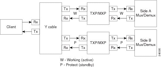
- Y-cable protected—In Y-cable protection, one transponder card is designated as active and the other as standby. The standby transponder card has the client-side laser turned off to avoid corrupting the signal transmitted back to the client. The active transponder monitors the signal from the trunk side and in the event of loss or signal failure, the system switches to the standby path. The following figure shows an example of a Y-cable protected link.
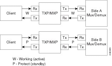
- Client-based 1+1—Two client signals are transmitted to separated line cards or transponder cards instead of using a Y-cable to split one client signal into two line cards or transponder cards. In client 1+1 protection, the failure and switchover is controlled by the client system. The following figure shows an example of a 1+1 protected link.
- Fiber-switched protection—The single client signal is injected into the client receive (Rx) port. It is then split into two separate signals on the two trunk transmit (Tx) ports. The two signals are transmitted over diverse paths. The far-end card chooses one of the two trunk Rx port signals and injects it into the Tx client port. The following figure shows an example of a fiber-switched protected link.
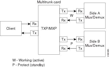
From CTP Release 10.5, fiber-switched protection is supported on a 10x10G-LC card. For more information, see Fiber-Switched Protection on a 10x10G-LC Card.
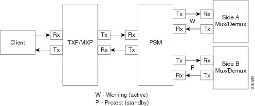
- PSM-OCH—Channel protection configuration provides protection at trunk level (like Fiber-Switched protection) for TXP/MXP that do not have dedicated Fiber-Switched cards. PSM splits the traffic originated by transponder trunk on working and protected TX ports. Working Tx (W-Tx) and protected TX (P-Tx) are connected to the add ports of Add-Drop stages adding the channel in two different directions. On the receiving direction PSM W-RX and P-RX are connected to the drop ports of Add-Drop stages receiving the channel from the two different directions. PSM switch selects a path among W-Rx and P-Rx ports so that only one direction at a time is connected to COM-RX ports and therefore to the TXP/MXP. The following figure shows an example of a PSM-OCH protected link.
From CTP Release 10.5, networks with PSM-OCH protection can be imported into CTP.
- Unprotected—Protection is not used.
- External card switch—Protection not used.
Fiber-Switched Protection on a 10x10G-LC Card
CTP Release 10.5 supports fiber-switched protection on a 10x10G-LC card. The 10x10G-LC cards support up to two splitter protection groups with one client and two trunk ports:
- First instance: Port 3 (client), Port 4 (Working trunk) and Port 6 (Protect trunk)
- Second instance: Port 7 (client), Port 8 (Working trunk) and Port 10 (Protect trunk)
You can also provision one instance of the fiber-switched protection with port 3 or port 7 as the client port, and up to 3 trunk ports. The operational mode of the card for fiber-switched protection is TXPP-10G. Fiber-switched protection is supported only for 10GE traffic with trunk mode set to Disable (NOFEC), Standard (FEC), or Enhanced (EFEC).
You can configure different wavelengths, threshold crossing alerts (TCAs), alarms threshold, facility and terminal loopbacks on the working and protect trunk ports.
Y-cable protection and fiber-switched protection cannot be configured on the same card.
To configure fiber-switched protection on a 10x10G-LC card, use the following procedure:
When you create a demand, choose Fiber Switched as the protection type from the Protection drop-down list in the Demand Editor dialog box.
Service Support
Cisco Transport Planner can support any subset of the following services:
- Alien (third-party DWDM interface)
- Cisco ONS 15530 2.5 Gbps Aggregated
- ONS 15530 10 Gbps Aggregated
- ONS 15530 Multirate (MR) Transport
- ONS 15530 Data Multiplexer (MXP)
- 2R Any Rate
- 3G-SDI
- Gigabit Ethernet
- 10GE—10 Gigabit Ethernet (LAN and WAN)
- D1 Video
- DVB-ASI—Digital Video Broadcast-Asynchronous Serial Interface
- DV-6000
- DPSK—Different Phase Shift Keying
- ESCON—Enterprise System Connection
- Fast Ethernet
- Fiber Channel 1G
- Fiber Channel 2G
- Fiber Channel 4G
- Fiber Channel 8G
- Fiber Channel 10G
- FICON—Fiber Connection 1G
- FICON Express 2G
- FICON 4G
- FICON 8G
- FICON 10G
- E3 over FE
- T3 over FE
- DS3 over FE
- High Definition Television (HDTV)
- ISC-3 Peer (1G)
- ISC-3 Peer (1G with STP)
- ISC-3 Peer (2G)
- ISC-3 Peer (2G with STP)
- ISC-3 Peer (2R)
- ISC-3 Peer (2R)
- ISC-Compat (ISC-3 Compatibility mode)
- HD-SDI
- HDTV
- OC-3
- OC-12
- OC-48
- OC-192
- OC-768
- OTU2
- SD-SDI
- SDI—Serial Data Input
- STM-1
- STM-4
- STM-16
- STM-64
- STM-256
- 10GE WAN-Phy
- 10GE LAN PHY
- 10GE LANtoWAN
- 100GE
- 40GE LAN PHY
- OTU1
- OTU2
- OTU2e
- OTU3
- OTU4
- Sysplex CLO—control link oscillator
- Sysplex ETR—external throughput rate
- LAN-WAN Conversion
The Sysplex CLO and Sysplex ETR services are supported only on the following topologies:
- Single span—Two terminal sites with 32MUX-O and 32DMX-O cards, 40MUX-O and 40DMX-O cards, 40WSS and 40DMX, or 32WSS and 32DMX or 32DMX-O cards installed and no intermediate sites in between.
- Point-to-Point—Two terminal sites with 32MUX-O and 32DMX-O cards. 40MUX-O and 40DMX-O cards, 40WSS and 40DMX, or 32WSS and 32DMX or 32DMX-O cards installed. Line amplifiers can be installed between the terminal sites, but intermediate (traffic terminating) sites cannot be installed.
- Two hubs—Two hub nodes in a ring with 32MUX-O, 32DMX-O, 32WSS, 40MUX-O, 40DMX, 40DMX-O, 40WSS, and 32DMX cards or 32DMX-O cards installed. Line amplifiers can be installed between the hubs.
For more information about the supported topologies for the ETR and CLO services, refer the Cisco ONS 15454 DWDM Configuration Guide .
The following features are available only when 100GE or OTU4 is selected as the service type during network creation:
- CRS line card 1-100GE-DWDM (FEC, EFEC [default], or HG-FEC) is available for Point-to-Point, P-Ring, and ROADM demands.
- (For Release 9.6.03 and later) MPO-MPO cables are available in the Net view and Site view of the BoM report. MPO-MPO cables are not available for combination cards. For example, MPO-MPO cables are not available if you have chosen 100G-LC-C+CFP-LC or 100G-LC-C+ASR as card type.
The encryption feature is available only:
- When 10GE LAN PHY, OTU2e, or OTU2 is selected as the service type during network creation.
- When 100GE is selected with TXP-100G operating mode cards.
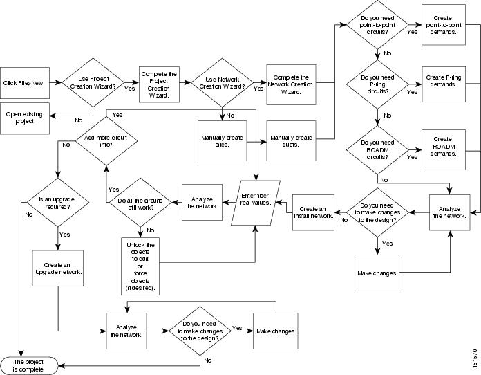
Cisco Transport Planner Process Flow
The following stages are used to complete a network design.
- Create a project using the Project Creation wizard.
- Create a network using the Create Network wizard. The Create Network wizards adds sites and places the fiber spans between the sites. A span represents a pair of fibers.
- Create a point-to-point, Aggregated Ethernet, TDM Aggregated, protected ring (P-ring), and/or ROADM service demand.
- Analyze the network design.
- If you would like to force automatic tool choices, adjust the design and repeat the analysis until you have reached the desired configuration.
- Create an Install copy of the network and update the parameters with real data from the field.
- Analyze the Install network.
- Create an upgrade copy of the network, as needed, to add forecasted channels.
Planning Traffic in Cisco Transport Planner
Traffic in Cisco Transport Planner is defined as an optical path for each pair of nodes requiring a service demand. An optical path is the combined channels between the two nodes. The following list gives definitions for some basic traffic items:
- Circuit—A single channel
between a pair of source and destination nodes. In addition to the source and
destination nodes and all the attributes that are common to the service
containing the circuit, a circuit has the following attributes:
– Present/forecast indication
– Routing direction for unprotected service
– ITU channel
– Optical bypass indication
- Demand—A set of circuits
with common characteristics, such as:
– Service demand label
– Number of existing circuits
– Number of forecasted circuits
– Client service type
– Protection type
– Optical bypass (number of channels and/or sites)
– Present/forecast indication WDM interface type (TXT or ITU-LC)
– WDM card type
– Source client interface (SR, IR, or LR)
– Destination client interface (SR, IR, or LR)
- Traffic demand—All traffic
between the same set of nodes. Both L-band and C-band are supported. The
following traffic demands are supported: P-ring, Fixed (point-to-point), and
Any-to-any (ROADM).
– In P-ring traffic demands, all the demands are used to support traffic topologies similar to bidirectional line switched rings (BLSRs) or multiplex section-shared protection rings (MS-SPRings). Each P-ring demand is between a pair of added/dropped nodes where BLSR-like (or MS-SPRing-like) traffic must exist. The number of circuits is the same for each demand, and is user-specified (from 1 to 40).
– In fixed (point-to-point) traffic demands, the set of nodes is restricted to two sites. The number of circuits is user-specified (from 1 to 40).
– In any-to-any (ROADM) traffic demands, a minimum of two nodes and a maximum of 40 ROADM nodes are supported. The any-to-any traffic demand allows each node to establish one or more circuits with the other nodes, either as a hub or meshed configuration. In a meshed configuration, each node defined in the set is connected to each of the nodes. This is the most common traffic type. In a hub configuration, the user-defined hub node is connected to each of the other nodes. ROADM circuits have the same protection types and services. The number of circuits is not user-specified and can vary from 0 to 40.
Note
In any-to-any (ROADM) traffic demand, the default routing strategy is Unprotected minimum hop count.A ROADM demand can have multiple client service types and support multiple DWDM card interfaces for each client service type. A ROADM demand supports the following routing strategies:
– Protected (Default)—Each node pair in the traffic demand is connected using two connections.
– Unprotected optimum optical path—Each node pair is connected using one connection. The unprotected optimum optical path minimizes the number of required optical amplifiers, but also restricts the number of channels that can be deployed among the nodes of the traffic demand (maximum of 40 channels between each node pair) in the installed network.
– Unprotected minimum hop count—Each node pair in the traffic demand is connected by one connection. The unprotected minimum hop count maximizes the number of channels (for unprotected traffic types only) that can be deployed among the nodes of the traffic demand, but requires a higher number of optical amplifiers on the unprotected optimum optical path (maximum of 40 channels between each node pair) in the installed network.
– Unprotected subnet—Each node pair in the traffic demand is connected using one connection. You can manually force connections on only one branch of the ring. For unprotected subnets, you must manually select one starting node of the branch and the direction the ring must be traversed to define the subnet, starting from the initial site. The branch direction is specified by defining the outgoing side first, referred to as the starting node. This routing strategy option allows you to exclude some critical paths and (with ROADM traffic demands containing two sites) to force each ROADM connection clockwise or counterclockwise.
Project Explorer Pane
The Project Explorer pane shows all of the open project information, including networks, network dependencies, sites, fibers, services, and so on. The user-defined traffic services are displayed as folders and icons in the Project Explorer pane, as shown in the following figure.
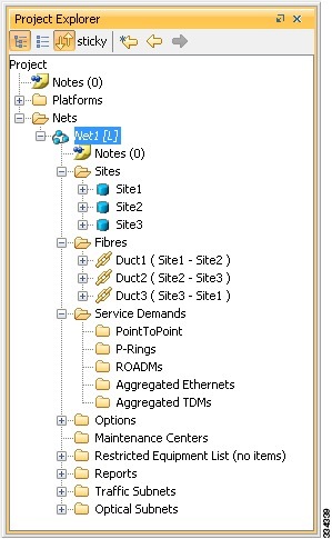
After you analyze a network design, the colors of the icons change according to the error/warning condition of the network design. The icons display in red if there are errors in the network design; orange if there are warnings but no errors; and green if there are no warnings or errors. The icon shows the color of the most severe condition. For more information about analyzing the network, see the Analyzing the Network.
The Project Explorer pane provides the following options to edit the parameters:
Multiple Selection
Click sticky in the Project Explorer pane toolbar to select multiple folders and icons in the Project Explorer tree or the Network View. Alternatively, hold the Ctrl key on the keyboard and select multiple folders and icons. The folders and icons corresponding to the selection in the Project Explorer pane are highlighted in the Network View and vice-versa. You can also select similar folders and icons by right-clicking them and choosing Select Similar in the menu. For example, by right-clicking a site choosing Select Similar in the menu, you can select all the sites in the Project Explorer pane. The Select Similar option is available only for the folders and icons in the Project Explorer pane that have properties. The properties that are common to the selected items are displayed in the Properties pane. If any property has a different value than the others, that value is highlighted in a different color in the Properties pane.
The following options are available when multiple folders and icons are selected:
Cisco Transport Planner Traffic in the Project Explorer Pane
Cisco Transport Planner represents all of the user-defined traffic services as folders and icons within the Project Explorer pane.
- Point-to-Point Traffic Demands
- P-Ring Traffic Demands
- ROADM Traffic Demands
- Aggregated Ethernet Demand
- TDM Aggregated Demand
Point-to-Point Traffic Demands
Point-to-point traffic demands appear in the Service Demands > PointToPoint folder in the Project Explorer pane. Each point-to-point traffic demand is categorized by its source and destination site names. All of the point-to-point services between the two sites appear under the designated demand name.
A point-to-point traffic demand includes the following information:
P-Ring Traffic Demands
Each protected ring (P-ring) traffic demand appears in the Project Explorer pane under the Service Demands > P-Rings folder.
All the P-ring channels between each site pair are listed under each P-ring traffic demand. Each demand is labeled with the following information:
ROADM Traffic Demands
Each ROADM traffic demand appears in the Project Explorer pane under the Service Demands > ROADMs folder. The ROADM folder contains each defined ROADM demand. You can define more demands for the same ROADM for the same set of nodes.
In the Project Explorer pane, each ROADM includes the ROADM demand name and a list of DWDM card types that support the client service types. Protection types appear in parentheses.
Aggregated Ethernet Demand
Each aggregated ethernet traffic demand appears in the Project Explorer pane under the Service Demands > Aggregated Ethernet folder. The Aggregated Ethernet folder contains each defined aggregated ethernet demand. Aggregated Ethernet demands are supported on ring and linear traffic subnets.
TDM Aggregated Demand
Each TDM aggregated demand appears in the Project Explorer pane under the Service Demands > Aggregated TDMs folder.
Note | TDM aggregated demands are supported only on a ring traffic subnet. |
Auto, Forced, and Locked Parameters
Parameters in CTP can be in one of three states:
- Auto— This parameter allows the highest degree of flexibility to CTP in designing a network. When you select Auto, CTP chooses the parameter value during network analysis.
- Forced—When you set a specific parameter value, other than Auto, CTP designs the network using these constraints. When a setting is forced, the item appears in blue italics in the Project Explorer pane.
- Locked—The state of a parameter after network analysis. The next time the analyzer is run, Cisco Transport Planner cannot change the value when it is in the Locked state. You can unlock an item using the Unlock command. For more information, see Unlocking Parameters in the Network Design and Forcing Manager.
Note | For the WSE card, the encryption option can be modified even when the demand is in locked state. This is available in the Upgrade or Release-upgrade networks and on A2A finalized demands that can be edited from A2A Finalized Circuits. When modifications are made without the unlock, the encryption parameter on the specific port of the WSE card is updated on analysis. |
Depending on the initial state, the network analyzer will:
Installing Cisco Transport Planner
Use the following procedure to install Cisco Transport Planner:
Uninstalling Cisco Transport Planner
Use the following procedure to uninstall Cisco Transport Planner:
| Step 1 | Click the
Uninstall CTP icon available at the location selected in Step 10 of the
Installing Cisco Transport Planner.
The graphical Uninstall CTP wizard is displayed. |
| Step 2 | Click Uninstall. |
| Step 3 | A progress bar
displays the uninstallation status. Click
Cancel at any time to stop the uninstallation.
When the uninstallation process is complete, a screen displays the files that could not be uninstalled. |
| Step 4 | Click Done to exit the uninstallation wizard. |
Launching the Cisco Transport Planner
Before you start the Cisco Transport Planner (CTP), you need to save the user profiles provided by Cisco Systems to the profiles folder available at the installation location. Access to CTP features depends on the user profile you select when you start CTP. The default profile is Base Network Designer.
To launch the CTP, perform the following steps:
| Step 1 | Launch Cisco
Transport Planner using any of the following options:
CTP validates the installed Java version in the system. If the installed version is Java 1.6 or Java 1.7, the CTP login dialog box is displayed.
| ||
| Step 2 | From the Current selected profile drop-down list, select the user profile. | ||
| Step 3 | Click
Continue to open the Cisco Transport Planner.
The login profile type appears in the lower-right corner of the CTP window. The Start Page is displayed. The Start Page provides the following options:
Selecting any of the above options opens a new tab. | ||
| Step 4 | Check the
Do not
show Start Page at startup check box to disable viewing the start
page when Cisco Transport Planner is started.
Check View Start Page check box under Tools > Option > Graphic > Start Page to enable displaying the Start Page when launching the CTP. |
Opening a Project
Use the following procedure to open an existing Cisco Transport Planner project. To create a new project, see Creating a Project.
| Step 1 | Click the project name under Open in the Tasks Pane. The project opens. If you do not see the project name listed, continue with Step 2. | ||
| Step 2 | Click Open in the Start Page, click Open under Project in the Tasks Pane, or in the File menu. | ||
| Step 3 | In the Open
Project dialog box, navigate to the desired folder and choose the project.
Click
Open. The Cisco Transport Planner project appears.
|
Loading and Unloading Networks
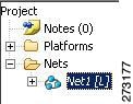
Each network in a project requires memory. To save memory, when Cisco Transport Planner opens a project, all networks are in the Unloaded state. An unloaded network appears in the Project Explorer pane with a “U” next to the network identifier. To load an unloaded network, double-click on the network folder in the Project Explorer pane, or right-click the network and choose Load from the shortcut menu.
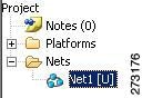
A loaded network appears in the Project Explorer pane with an “L” next to the network identifier. To unload a loaded network, right-click the network icon in the Project Explorer pane and choose Unload from the shortcut menu.
Note | When you load a network containing an alien interface that is not present in the parts database (DB), warning messages are displayed. |
Saving a Project
Use the following procedure to save a project:
Closing a Project
Use the following procedure to close a Cisco Transport Planner project:
| Step 1 | From the File menu, choose Close. |
| Step 2 | In the Save Project dialog box, click Yes to save or No to close without saving changes. |
| Step 3 | If you clicked Yes and have not previously saved the project, the Save Project dialog box appears. Enter the name of the project and click Save. The project closes. |
| Step 4 | To exit Cisco Transport Planner, choose Exit from the File menu. |
Deleting the CTP Cache
To delete the CTP cache, perform the following steps:
Note | CTP must be restarted to delete the CTP cache. |
| Step 1 | From the Tools menu, choose Delete Cache. |
| Step 2 | Click Yes to delete the CTP cache or No to postpone cache deletion. |
| Step 3 | When you click Yes, an information message is displayed prompting you to restart CTP now or later. If you do not want to restart CTP immediately, cache deletion is postponed to the next restart. |
| Step 4 | Before you restart, save your project and choose File > Close to close the project. |
| Step 5 | If you click on Restart Now, CTP cache is deleted and CTP restarts automatically. |
| Step 6 |
To restart CTP later, choose File > Restart.
A message is displayed prompting you to continue with restart. Click Yes to restart CTP. A message is displayed prompting you to continue with cache deletion now or later. |
| Step 7 | Click Yes to delete the CTP cache or No to postpone cache deletion. |
Performing Software Updates in CTP
CTP enables you to update the CTP software automatically or manually.
- Performing Automatic Software Updates in CTP
- Performing Manual Software Updates in CTP
- Performing Software Update Rollback
Performing Automatic Software Updates in CTP
This section explains how to perform an automatic software update.
| Step 1 | When CTP is launched, it checks for the latest software update automatically. If available, the following dialog box appears: Online Update Available, Would you like to Update CTP? Click Yes. | ||
| Step 2 | The Software Update Dialog box appears listing the applicable software updates. Select the required software update and click Apply. | ||
| Step 3 | The Update
Successful message appears. Click
OK.
|
Performing Manual Software Updates in CTP
Contact the Cisco Sales/Account team to get the software update files.
This section explains how to perform a manual software update.
| Step 1 | In the CTP Help menu, go to Help > Check updates. The update CTP dialog box appears. |
| Step 2 | Click Browse. |
| Step 3 | Select the .upz update file and click OK. |
| Step 4 | The Software Update Dialog box appears listing the applicable software updates. Select the required software update and click Apply. |
| Step 5 | The Update Successful message appears. Click OK. |
| Step 6 | Delete the cache and restart CTP. |
Performing Software Update Rollback
CTP allows rollback of software updates. A single rollback moves the CTP software to the previous state (prior to the software update). For example, if there are two updates applied one by one—Update 1 and Update 2, after the first rollback, CTP removes Update 2 and retains Update 1. Further rollback(s) are needed if multiple updates are present.
This section explains how to perform a rollback.
| Step 1 | Press R while CTP is launching. The CTP launch is interrupted to perform a software rollback. | ||
| Step 2 | Click
Yes to
confirm software rollback. The rollback successful dialog box appears.
|
Setting Cisco Transport Planner Options
Cisco Transport Planner provides numerous options for customizing the tool and the design.
Note | The following procedures for setting options using the Tools menu apply to new projects during project creation. To change an existing (open) project, click the desired item in the Project Explorer pane Subnets folder and edit the parameter in the Properties pane. |
- Setting the Graphical Display
- Setting the Default Software Release
- Setting the Default Platform Values
- Setting the Default Project Values
- Defining Third-Party DWDM Interfaces
- Exporting User Options, Price Lists or Alien Definitions
- Importing User Options, Price Lists or Alien Definitions
- Importing the OSMINE Configuration File
- Resetting the Default Layout
- Adding User Profiles
- Understanding Sides Labeling
Setting the Graphical Display
Use the following procedure to set the Cisco Transport Planner graphical display:
| Step 1 | From the Tools menu, choose Options. | ||
| Step 2 | In the Options Explorer dialog box, right-click the Graphic folder and choose Expand from the shortcut menu. | ||
| Step 3 | Click
Chart
Panel and complete the following:
| ||
| Step 4 | To change the color scheme for Cisco Transport Planner, click Look & Feel and choose the desired scheme from the drop-down list. | ||
| Step 5 | To enable displaying the Start Page when launching Cisco Transport Planner, check the View Start Page checkbox. | ||
| Step 6 | To change the
appearance of the Project Explorer tree, click
Project
Explorer
and complete the following tasks as needed:
| ||
| Step 7 | To change the
NtView Name tab appearance, click
Network
View and complete the following tasks as needed:
The duct details displayed in the NtView Name tab is shown in the following figure . 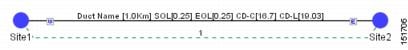 The ducts in a network carry a predefined number of wavelengths (2, 4, 8, 16, 32, 64, or 80). Wavelength usage is the percentage of wavelength used by these ducts. The percentage of wavelength used in individual ducts are displayed in various colors. Use the Wavelength Usage (%)option to assign any one of the four predefined colors to the different percentage of wavelength used. The custom values remain until the cache is deleted. After the cache is deleted, CTP populates the following default values: – Green—25% – Yellow—50% – Orange—75% – Red—100% For example, the wavelength usage in an 80 wavelength duct that uses 40 wavelengths is 50%. This duct is displayed in yellow. The valid values range from 1 to 100. If you enter a value greater than 100, it is considered as 100, negative value is considered as 1, while 0 is ignored. The ducts that do not carry any wavelength are displayed in grey.
For more information on wavelength usage, see Table "Menu and Toolbar Option". | ||
| Step 8 | To change the
Network Mgmt Tree tab appearance, complete the following tasks as needed:
| ||
| Step 9 | To change the
layout appearance, click
Layout
View and complete the following tasks as needed:
| ||
| Step 10 | Click Ok. |
Setting the Default Software Release
Use the following procedure to set the default software release for CTP. This release will be used as the default software release when creating a project. See Creating a Project.
Setting the Default Platform Values
Use the following procedure to establish the default traffic mapping, dense wavelength division multiplexing (DWDM) design, and default layout settings for a particular platform and system release. The default settings appear during project creation. All options that you specify can be changed after project creation on a per-span basis.
| Step 1 | From the Tools menu, choose Options. | ||||||||||||
| Step 2 | In the Options Explorer dialog box, right-click Platform and choose Expand from the shortcut menu. | ||||||||||||
| Step 3 | Click the
desired
System
Release
folder and complete the following tasks as needed:
Choose the required settings:
| ||||||||||||
| Step 4 | Click the
Layout folder and complete the following settings as
required:
| ||||||||||||
| Step 5 | Click the
Restricted Equipment folder. To restrict a unit,
check the corresponding check box in the Restricted column for that unit.
To change the setting back to unrestricted, uncheck the check box. To apply restricted list changes to an open project, complete the following:
| ||||||||||||
| Step 6 | Click theFiber Options folder
and specify the fiber parameters as required:
| ||||||||||||
| Step 7 | Click the
Traffic Mapping
folder and complete the following tasks as needed.
| ||||||||||||
| Step 8 | Click the
DWDM
Design Rules folder and complete the following tasks as needed:
| ||||||||||||
| Step 9 | Click OK. |
Setting the Default Project Values
Use the following procedure to set the default project settings and repair time. These defaults will appear during project creation.
| Step 1 | From the Tools menu, choose Options. |
| Step 2 | In the Options
Explorer dialog box, click
Project and complete the following tasks to set the
defaults that appear in the Project Creation wizard:
|
| Step 3 | Click
General and complete the following tasks:
|
| Step 4 | Click
BoM and complete the following:
|
| Step 5 | Click OK. |
Defining Third-Party DWDM Interfaces
Cisco Transport Planner allows you to define a third-party DWDM interface to be used in project creation. After you define third-party DWDM interfaces, you can choose them when creating traffic demands. For more information on defining third-party interfaces, see Appendix D, Third-Party DWDM Wavelength Interface Model.
Note | If you create a network design with a third-party interface and need to share the design with other users, you must provide not only the saved network MPZ file but also the exported database file containing the third-party interface definition. To view this project, the other user first must import the database with the third-party interface values. |
Use the following procedure to define a third-party DWDM interface:
| Step 1 | Click
Tools
> DB Parts Mgmt. The DB Parts Manager dialog box appears.
| ||||||||||||||||||||||||||||||||||||||||||||||||||||||||||||||||||||||||||||||||||||||||||||||||||||||||||||||||||||||||||||||||||||||||||
| Step 2 | Right-click Platform Parts and choose Expand from the shortcut menu. | ||||||||||||||||||||||||||||||||||||||||||||||||||||||||||||||||||||||||||||||||||||||||||||||||||||||||||||||||||||||||||||||||||||||||||
| Step 3 | Right-click Group and choose New Group from the shortcut menu. The new group appears under Group and in each system release under parts DB. | ||||||||||||||||||||||||||||||||||||||||||||||||||||||||||||||||||||||||||||||||||||||||||||||||||||||||||||||||||||||||||||||||||||||||||
| Step 4 | In the Group
Editor dialog box, complete the following information:
| ||||||||||||||||||||||||||||||||||||||||||||||||||||||||||||||||||||||||||||||||||||||||||||||||||||||||||||||||||||||||||||||||||||||||||
| Step 5 | In the parts DB for the desired system release, click the group that you created. | ||||||||||||||||||||||||||||||||||||||||||||||||||||||||||||||||||||||||||||||||||||||||||||||||||||||||||||||||||||||||||||||||||||||||||
| Step 6 | In the Parts tab of the DB Parts Manager dialog box, right-click and choose Client and then Alien from the shortcut menu. A new row appears on the Parts tab for the client hardware. | ||||||||||||||||||||||||||||||||||||||||||||||||||||||||||||||||||||||||||||||||||||||||||||||||||||||||||||||||||||||||||||||||||||||||||
| Step 7 | Double-click the row to open the Alien dialog box. | ||||||||||||||||||||||||||||||||||||||||||||||||||||||||||||||||||||||||||||||||||||||||||||||||||||||||||||||||||||||||||||||||||||||||||
| Step 8 | In the General tab of the Alien dialog box, type the name of the card in the Name field and the enter the Label name. | ||||||||||||||||||||||||||||||||||||||||||||||||||||||||||||||||||||||||||||||||||||||||||||||||||||||||||||||||||||||||||||||||||||||||||
| Step 9 | Click the
Istance tab and complete the following:
| ||||||||||||||||||||||||||||||||||||||||||||||||||||||||||||||||||||||||||||||||||||||||||||||||||||||||||||||||||||||||||||||||||||||||||
| Step 10 | Click
the Physical
Ports tab and in the Label column, type a label for each port.
The CTC Ports and TL1 Ports tabs are not applicable for third-party interfaces. | ||||||||||||||||||||||||||||||||||||||||||||||||||||||||||||||||||||||||||||||||||||||||||||||||||||||||||||||||||||||||||||||||||||||||||
| Step 11 | Click Ok. | ||||||||||||||||||||||||||||||||||||||||||||||||||||||||||||||||||||||||||||||||||||||||||||||||||||||||||||||||||||||||||||||||||||||||||
| Step 12 | In the Parts tab of the DB Parts Manager dialog box, right-click and choose Software and then Alien from the shortcut menu. A new row appears on the Parts tab for the client software. | ||||||||||||||||||||||||||||||||||||||||||||||||||||||||||||||||||||||||||||||||||||||||||||||||||||||||||||||||||||||||||||||||||||||||||
| Step 13 | Double-click the row to open the AlienSoft dialog box. | ||||||||||||||||||||||||||||||||||||||||||||||||||||||||||||||||||||||||||||||||||||||||||||||||||||||||||||||||||||||||||||||||||||||||||
| Step 14 | In the General
tab, complete the following:
| ||||||||||||||||||||||||||||||||||||||||||||||||||||||||||||||||||||||||||||||||||||||||||||||||||||||||||||||||||||||||||||||||||||||||||
| Step 15 | Click any of
the following depending on the client card that you choose and proceed to Step
16:
| ||||||||||||||||||||||||||||||||||||||||||||||||||||||||||||||||||||||||||||||||||||||||||||||||||||||||||||||||||||||||||||||||||||||||||
| Step 16 | Complete the
following (see
"Supported
Combination for 40 Gbps Third Party Interface" table through
"Supported
Combination for 10 Gbps Third Party Interface" table for supported value
combinations):
 | ||||||||||||||||||||||||||||||||||||||||||||||||||||||||||||||||||||||||||||||||||||||||||||||||||||||||||||||||||||||||||||||||||||||||||
| Step 17 | Click
Ok.
The following table lists the supported combinations for 40-Gbps third party interfaces.
The following table lists the supported combinations for 10-Gbps third party interfaces.
The following table lists the supported combinations for 2.5-Gbps third party interfaces.
| ||||||||||||||||||||||||||||||||||||||||||||||||||||||||||||||||||||||||||||||||||||||||||||||||||||||||||||||||||||||||||||||||||||||||||
Exporting User Options, Price Lists or Alien Definitions
Use the following procedure to export user options, price lists, maintenance contracts, and the parts database files. The export command creates a ZIP file that includes all of the created files.
| Step 1 | From the Tools menu, choose Export. The Export dialog box appears. |
| Step 2 | In the Export dialog box, enter a file path and name in the file name field. To export to an existing file, click the ... button and navigate to the desired folder and file. Click Select to choose the file. |
| Step 3 | To select the items to export, complete the following as needed: |
| Step 4 | Click Ok. |
Importing User Options, Price Lists or Alien Definitions
Use the following procedure to import user options, price lists, maintenance contracts, and the parts database files. You can import a ZIP file of multiple exported items or an individual TXT file.
| Step 1 | From the Tools menu, choose Import. The Import dialog box appears. |
| Step 2 | In the Import dialog box, click the ... button and navigate to the desired folder and file. Click Select to choose the file to import. |
| Step 3 | Click load. |
| Step 4 | If you selected
a single TXT file, skip this step and go to Step 5. If you selected a ZIP file
with multiple exported options, complete the following as needed:
|
| Step 5 | Click OK. |
| Step 6 | In the confirmation dialog box, click OK. |
Importing the OSMINE Configuration File
The OSMINE configuration updates are provided in an OSMINE configuration file. When a new OSMINE configuration file is available, use this procedure to import it. The networks analyzed after the import operation will be OSMINE compliant as per the configurations provided in the OSMINE configuration file.
| Step 1 | From the Tools menu, choose OSMINE File Import. The Select OSMINE Config File dialog box is displayed. |
| Step 2 | Browse and select the OSMINE configuration XML file. |
| Step 3 | Select the MSTP release from the drop-down list. |
| Step 4 | Click OK. The new configuration is loaded into CTP. |
Resetting the Default Layout
Your graphical layout settings are saved when you exit Cisco Transport Planner. The next time that you launch Cisco Transport Planner, the layout appears as it did upon exiting. The default graphical layout includes items such as whether the panes are visible and/or docked.
To return to the Cisco Transport Planner default layout, choose Default Layout from the View menu. To restore the user modified layout, choose My Default View from the View menu.
Adding User Profiles
A user profile is a set of privileges used for running Cisco Transport Planner. Each profile offers different capabilities. Cisco Transport Planner is packaged with the Network Designer profile, but you can add other user profile types provided by Cisco. All the procedures in the Cisco Transport Planner DWDM Operations Guide are written for users with Network Designer access.
Use the following procedure to add a user profile to Cisco Transport Planner:
| Step 1 | Close all open instances of Cisco Transport Planner. |
| Step 2 | Identify the folder where Cisco Transport Planner is installed on your computer, see Launching the Cisco Transport Planner, section on page 1-16. |
| Step 3 | Create a profile folder; if profile folder already exists, go to Step 4. |
| Step 4 | Copy the profile JAR file provided by Cisco Systems into the profile folder. |
| Step 5 | Launch Cisco Transport Planner. For more information, see Launching the Cisco Transport Planner, section on page 1-16. The new profile will appear in the Current Selected Profile drop-down list. |
Understanding Sides Labeling
In Cisco Transport Planner Software R8.5 and later, the label for each supported site structure is different from the labels that have been used in the previous releases. The following table summarizes the labeling format in Cisco Transport Planner.
|
Sites |
Labeling in Previous Releases |
Default labeling in Cisco Transport Planner Software R8.5 and later |
|---|---|---|
|
Terminal/Terminal+ |
Only one side is created and labeled, T. |
Label A is used for the existing side. |
|
Line/Line+ |
Two sides are created and are labeled, West and East. |
Labels A and B are used for the existing sides. |
|
Multidegree with PP-MESH-4 |
— |
Labels A, B, C, and D are used for the existing sides. |
|
Multidegree with PP-MESH-8 |
— |
Labels A, B, C, D, E, F, G, and H are used for the existing sides. |
|
PSM Line |
— |
Labels Aw and Ap are used for the existing sides, where w stands for working and p stands for protection. |
|
PSM Section |
— |
Labels Aw and Ap are used for the existing sides, where w stands for working and p stands for protection. |
Note | The default labels applied to the sides can be edited. For more information about editing side labels, see Editing Side Labels. |
Understanding Hybrid Configuration
Typically a node has ONS 15454 MSTP configuration with add/drop units like 40-MUX-C/40-DMX-C, ROADM units and so on. However, the node configuration can also have ONS 15454 amplifiers along with ONS 15216 FlexLayer add/drop units like FLB-2s, FLA-8s, and FLD-4s, and is known as Hybrid 15454 ONS configuration. A network design can have up to 80 channels in a typical MSTP configuration; however, in a Hybrid configuration the number of channels is restricted to 40. In a Hybrid configuration, the Data Connection Network (DCN) manages the traffic instead of Optical Service Channel (OSC). Hybrid nodes are add/drop nodes with express traffic and are comparatively less expensive than MSTP nodes.
Understanding the Pay As You Grow Feature
The Pay As You Grow (PAYG) feature enables you to implement a cost effective solution when the wavelength requirements are comparatively less than the maximum capacity of the network. Instead of purchasing a standard card that is configured to work on maximum supported wavelengths, you can purchase a PAYG license that comprises of license restricted cards and a base license. The license restricted cards support only a number of wavelengths for which the licenses are installed on the card. The base license supports only 10 wavelengths. Therefore, a license restricted card having only the base license will support only ten wavelengths even if its maximum capacity is to support 40 wavelengths. The cost of the PAYG license is less than the cost of the standard card. For more information about the PAYG licenses, see Pay As You Grow Licensing.
When there is a need of more than ten wavelengths, additional licenses can be purchased to support the increased demand. Each new license supports ten additional wavelengths. Therefore, the PAYG functionality significantly reduces the initial setup cost and enables the purchase of additional wavelength capacity on a need basis.
During the analysis of the network, the CTP algorithm decides on whether to use a standard card or a PAYG license depending on the lower implementation cost.
The cards and units that support a PAYG bundle are:
- 40-SMR1-C
- 40-SMR2-C
- 80-WXC-C
- AR-MXP
- AR-XP
- 100G-LC-C
- 100G-CK-LC-C
- 10X10G-LC
- 15216-MD-40-ODD
- WSE
- 15216-EF-40-ODD
- 400G-XP-LC
The PAYG licensing is applied to each side of every site. The license depends on the cards placed on that side and the wavelengths that are added, dropped, or expressed. The PAYG licensing is not dependent on site, type, or functionality.
The applied PAYG bundle is displayed in the Bill of Material of the site. To view it, right-click the site in the Project Explorer pane and select the Bill of Material option from the shortcut menu.
The PAYG bundle to which a card is associated is displayed in the card property. To view it, select the card in the Project Explorer pane; the PAYG bundle name is displayed for the Payg Bundle property in the Properties pane.
Unlock Pay As You Grow Bundles
When a license restricted card is associated with a PAYG bundle, the association is maintained for future analysis. Therefore, if the network is analyzed with increased wavelength demands, CTP adds additional licenses even though using a standard card is cost effective.
During a network upgrade, the association of the license restricted card with the PAYG bundle is not modified unless the Unlock Pay As You Grow Bundle option is selected. Right-click the site either in the Project Explorer pane or in the NtView Name tab, and select the Unlock Pay As You Grow Bundles option from the shortcut menu. On selecting the Unlock Pay As You Grow Bundle option all the PAYG bundle information from a previous analysis are deleted and are recalculated when the network is analyzed again.
Note | The Unlock Pay As You Grow Bundle option is enabled only in the Upgrade or Install mode. |
Forcing PAYG Bundles On a Card
The Developer and Optical Designer profile users can decide whether to associate a card with the PAYG bundle or not. Select the card in the Project Explorer pane; the Force Payg drop-down list is displayed in the Properties pane. The options available are:
- Auto—The PAYG bundle or the standard card is used based on cost effectiveness.
- Yes—The card is always associated with the PAYG bundle even if using the PAYG bundle is not the most cost effective solution.
- No—The card is never associated with a PAYG bundle even if using the PAYG bundle is a more cost effective solution.
Note | The Force Payg drop-down list is enabled only in the Upgrade and Install modes, when the card is in the locked state. |
 Feedback