- Overview
- User Interface
- Plan Objects
- Traffic Demand Modeling
- Simulation
- Simulation Analysis
- Forecasting Traffic
- IGP Simulation
- MPLS Simulation
- Quality of Service Simulation
- BGP Simulation
- Advanced Routing with External Endpoints
- VPN Simulation
- Multicast Simulation
- Layer 1 Simulation
- Metric Optimization
- LSP Optimization
- SR-TE Optimization
- Changeover
- Reports
- Cost Modeling
- Plot Legend for Design Layouts
Cisco WAE Design 6.2 User Guide
Bias-Free Language
The documentation set for this product strives to use bias-free language. For the purposes of this documentation set, bias-free is defined as language that does not imply discrimination based on age, disability, gender, racial identity, ethnic identity, sexual orientation, socioeconomic status, and intersectionality. Exceptions may be present in the documentation due to language that is hardcoded in the user interfaces of the product software, language used based on RFP documentation, or language that is used by a referenced third-party product. Learn more about how Cisco is using Inclusive Language.
- Updated:
- July 31, 2015
Chapter: Multicast Simulation
Multicast Simulation
WAE Design supports source-specific multicast (SSM), which is a method of delivering multicast packets to receivers only from a specified source address that is requested by the receiver. By limiting the source, SSM reduces resource requirements and improves security.
SSM Parameters
WAE Design supports SSM multicast, which is specified by an (S,G) parameter per multicast flow. The (S,G) pair and is labeled using a dot-decimal notation similar to IP addresses (for instance, 1.1.1.1, 2.2.2.2). Each (S,G) pair is the name of a multicast flow, and each flow is listed in the Multicast Flows table.
Discovered Versus Simulated Multicast Flows
How you work with multicast flows within WAE Design differs depending on whether the multicast flow was discovered by WAE Collector or whether you are simulating it ( Table 14-1 ).
|
|
|
|
|---|---|---|
WAE Collector discovers multicast flows ((S,G) pairs), and multicast traffic is derived from the Multicast Flow Traffic table (accessed from the Multicast Flows tab after selecting the Edit->Traffic menu). |
First, manually create the multicast flow, defining both the source (S) and the destinations (G). Next, create a demand that links the source to these multicast destinations, allowing the routing to be simulated through the network. |
|
Each discovered multicast flow includes multicast flow hops, which are node-interface combinations through which the multicast path flows. The Multicast Demand initializer uses multicast flow hops to determine multicast sources and destinations. |
||
WAE Collector discovers multicast flow hops on interfaces that are external to the plan file. These are interfaces from a plan node to an external node, or from an external node to a plan node. The Multicast Demand initializer uses multicast flow external hops to determine multicast sources and destinations. |
When you create a demand, it determines the path to take, but multicast external flow hops are not identified. |
|
WAE Collector does not identify a list of multicast destinations for each flow. The Multicast Demand initializer generates destinations from the Multicast Flow Hops and Multicast Flow External Hops tables. |
Specify destinations (nodes, interfaces, external AS’s, or external endpoints) when you create multicast flows. When creating multicast demands, specify these as multicast destinations. |
|
|
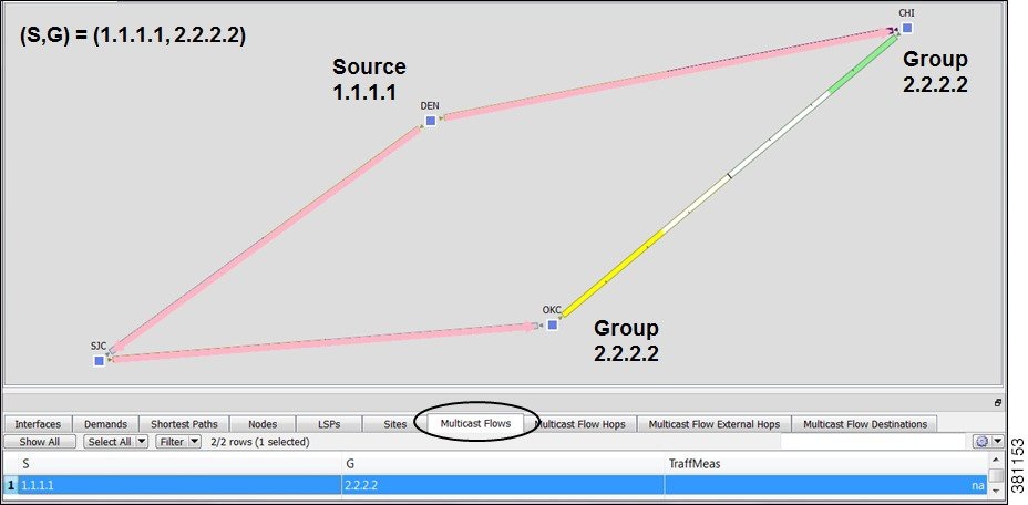
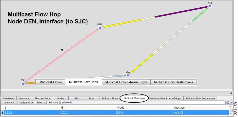
Figure 14-2 Multicast Flow Hops
Global Multicast Simulations
Flow Hops
If a plan file contains multicast information discovered by WAE Collector, then it includes the current hops taken by multicast flows. You can specify that WAE Design multicast simulations should follow these flow hops if possible. This is useful, for example, when calculating incremental routing changes on the current network state, such as those caused by a failure. For planning purposes, when current state is not relevant, you can change this behavior to disregard the multicast flow hops.
WAE Design uses network state in its multicast simulation. You can set simulations to take into account multicast flow hops, as follows.
Step 1![]() Select the Edit->Network Options menu or click the Network Options icon in the Visualization toolbar.
Select the Edit->Network Options menu or click the Network Options icon in the Visualization toolbar.
Step 2![]() Select the Simulation tab.
Select the Simulation tab.
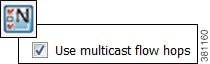
Step 3![]() To use or disregard multicast flow hops in simulation, select or deselect the “Use multicast flow hops” option accordingly, and click OK.
To use or disregard multicast flow hops in simulation, select or deselect the “Use multicast flow hops” option accordingly, and click OK.
Cisco Next Hop
For manually inserted demands, all SSM demand traffic for the (S,G) pair (multicast flow) goes through any interface that is traversed by that demand. For more information, see the Simulated Multicast Demands section.
However, you can set WAE Design to use Cisco next hops, which are calculated using a hash on S and G for a multicast flow (S,G). The hash calculation is different in IOS and IOS XR. The default behavior is that of IOS. The IOS XR hash is used on all nodes whose OS field starts with IOS XR.
Step 1![]() Select the Edit->Network Options menu or click the Network Options icon in the Visualization toolbar.
Select the Edit->Network Options menu or click the Network Options icon in the Visualization toolbar.
Step 2![]() Select the Protocols tab.
Select the Protocols tab.
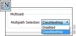
Step 3![]() Select CiscoNextHop from the Multicast, Multipath Selection list, and click OK.
Select CiscoNextHop from the Multicast, Multipath Selection list, and click OK.
Multicast Demands
For discovered multicast flows, you can insert demands manually or use the initializer.
For simulated multicast flows, create demands manually. For information on demands in general, see the Traffic Demand Modeling chapter.
To find demands associated with a multicast flow, right-click either a multicast flow or multicast flow destination, and select Filter to Demands. Conversely, to find multicast flows associated with demands, right-click a demand and select Filter to -> Multicast Flows.
Initialized Multicast Demands
The initializer creates simulated multicast flows corresponding to the discovered multicast flows. The demand traffic for all traffic levels existing is set to the traffic measured in the multicast flow. Following is how WAE Design determines the source and destination.
- Source —WAE Design first looks for an external endpoint with the same source (S) name as the source of the discovered multicast flow. If this source does not exist, WAE Design infers it from the multicast flow hops that have traffic going out of them, but none coming in. The inferred source can be a node or external endpoint.
- Destination —WAE Design first looks for multicast flow destinations with the same (S,G) name as those in the discovered multicast flow. If these multicast node destinations do not exist, WAE Design infers them from the multicast flow hops that have traffic going into them, but none coming out. WAE Design also infers multicast external flow hops if traffic is leaving a node in a direction that is outside the plan. These destinations are populated in the Multicast Flow Destinations table.
To run this initializer, select the Initializers->Multicast Demands menu.
Simulated Multicast Demands
For manually inserted demands, all SSM demand traffic for the (S,G) pair (multicast flow) goes through any interface that is traversed by that demand. SSM demands are routed to take the shortest path from the destination to the source, rather than from the source to the destination, as unicast demands do. By default, multicast multipath is disabled. If two paths of equal cost exit from a node on the route back to the source, the path is chosen based on these parameters.
- The remote interface with the highest IP address is used.
- If IP addresses are not available, the router name with the lowest lexicographical name is used.
However, you can set WAE Design to use the Cisco next-hop multicast, multipath selection method. For information, see the Cisco Next Hop section.
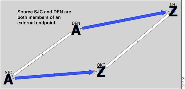
The sources of these multicast demands can be nodes, interfaces, external AS’s, or external endpoints. Using interfaces enables you to specify the exact interface on which demand traffic is entering. Using external endpoints enables you to model situations where the multicast source is outside of the nodes in the plan, and there is more than one possible entry point of the traffic flow into and through the interfaces in the plan.
In this example, the selected demand has a node source of DEN, and a multicast destination containing two nodes: CHI and OKC. The source node (S) is marked by A, and the destinations in the receiver group (G) are marked by Z.

You can model a source that is outside the plan using external endpoints. In this example, the demand’s source is an external endpoint that contains SJC and DEN as members. The multicast destination includes both CHI and OKC.
For instructions on how to create multicast demands, see Create Demands for Multicast Flows.
View Multicast Flows
To highlight discovered multicast flows and multicast flow hops in the plot, select them from their respective tables. To view sources and destinations of multicast demands, select the demand from its table. The source is identified in the plot by A and the destinations are identified by Z.
Create Multicast Flows
The easiest and recommended method of creating multicast flow destinations is to do so while creating its associated multicast flows, as follows.
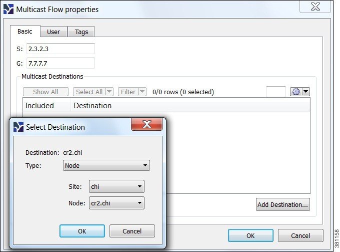
Step 1![]() Either select the Insert->Multicast Flow menu, or right-click the plot and select New->Multicast Flow from the context menu. A Multicast Flow dialog box appears.
Either select the Insert->Multicast Flow menu, or right-click the plot and select New->Multicast Flow from the context menu. A Multicast Flow dialog box appears.
Step 2![]() In the S field, identify the source node by entering its dot-decimal name. For example, 2.3.2.3.
In the S field, identify the source node by entering its dot-decimal name. For example, 2.3.2.3.
Step 3![]() In the G field, identify the collective name for all receiver nodes (destinations) by entering its dot-decimal name. For example, 7.7.7.7.
In the G field, identify the collective name for all receiver nodes (destinations) by entering its dot-decimal name. For example, 7.7.7.7.
Step 4![]() Add destinations to the receiver group.
Add destinations to the receiver group.
a.![]() Click Add Destination. A Select End Point dialog box appears.
Click Add Destination. A Select End Point dialog box appears.
b.![]() In the Type list, select either a node, interface, external AS, or external endpoint.
In the Type list, select either a node, interface, external AS, or external endpoint.
c.![]() If you are adding a node to the receiver group, select both the site and node name of the destination point in the multicast flow.
If you are adding a node to the receiver group, select both the site and node name of the destination point in the multicast flow.
If you are adding an interface, select the site, the node, and the interface.
If you are adding an external AS, select the external AS name and node for the destination point.
If you are selecting an external endpoint, select its name.
d.![]() Click OK. These values now appear in the Multicast Flow dialog box where you can further disable or enable them from participating in the multicast flow.
Click OK. These values now appear in the Multicast Flow dialog box where you can further disable or enable them from participating in the multicast flow.
Step 5![]() Repeat steps 4A-4D for each destination in the multicast flow.
Repeat steps 4A-4D for each destination in the multicast flow.
Step 6![]() Click OK in the Multicast Flow dialog box. Note if you close without clicking OK again, the above changes are not saved.
Click OK in the Multicast Flow dialog box. Note if you close without clicking OK again, the above changes are not saved.
After creating the multicast flow, to make it meaningful you need to create demands for the multicast flows. See Create Demands for Multicast Flows.
Create Demands for Multicast Flows
Step 1![]() Either select the Insert->Demand menu, or right-click the plot and select New->Demand. A New Demand dialog box appears.
Either select the Insert->Demand menu, or right-click the plot and select New->Demand. A New Demand dialog box appears.
Step 2![]() In the Name field, enter the name of the demand.
In the Name field, enter the name of the demand.
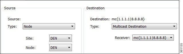
Step 3![]() In the Source area, define the source (S) of the multicast flow.
In the Source area, define the source (S) of the multicast flow.
a.![]() From the Type list, select the source as a node, interface, external AS, or external endpoint.
From the Type list, select the source as a node, interface, external AS, or external endpoint.
b.![]() For node sources, select both the site and the node.
For node sources, select both the site and the node.
For interface sources, select the site, node, and the interface.
For external AS’s, select both the external AS and the node within the plan file through which this external traffic flows.
For external endpoints, select its name.
Step 4![]() In the Destination area, define the receiver group (G) of the multicast flow.
In the Destination area, define the receiver group (G) of the multicast flow.
a.![]() Select Multicast Flow Destination from the Type list.
Select Multicast Flow Destination from the Type list.
b.![]() Select the receiver that identifies the simulated multicast flow (S,G) from the Receiver list.
Select the receiver that identifies the simulated multicast flow (S,G) from the Receiver list.
Step 5![]() Optional: Complete all other fields as needed.
Optional: Complete all other fields as needed.
Toggle Multicast Flow Destinations to On and Off
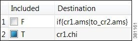
Step 1![]() In the Multicast Flows table, double-click the multicast flow. A Multicast Flow Properties dialog box appears with a list of existing destinations. Each destination appears with a T next to it if it is currently part of the receiver group or an F it exists, but is not part of the receiver group.
In the Multicast Flows table, double-click the multicast flow. A Multicast Flow Properties dialog box appears with a list of existing destinations. Each destination appears with a T next to it if it is currently part of the receiver group or an F it exists, but is not part of the receiver group.
Step 2![]() To enable or disable the multicast flow destination, click its associated T/F value.
To enable or disable the multicast flow destination, click its associated T/F value.
Step 3![]() Click OK in the Multicast Flow dialog box. Note if you close without clicking OK again, the change is not saved.
Click OK in the Multicast Flow dialog box. Note if you close without clicking OK again, the change is not saved.
 Feedback