Managing Templates and Device Objects

A template is a container of configurations, which can be applied to a target such as a device or a router.

Cisco VTS supports the following template types:
  • Overlay Templates—The following types of overlay templates are supported.
    • Route templates—A route template is a template that lets you configure static routes and route targets. This template can be applied to a tenant or a router. It is supported in a set up that has only Cisco ASR 9000 Series Aggregation Services Routers as DCI.

      Only integrated DCI mode is supported. VRF-peering mode is not supported.

    • L3 Service Extension templates—An L3 Service Extension template allows you to extend Cisco VTS Layer 3 service configuration on routers or tenants.

      The configuration you define in the service extension template, along with the out-of-the-box Cisco VTS L3 configuration, will be pushed to the device to get the combined configuration on the device. Service extension templates do not allow you to configure any parameter that Cisco VTS configures out-of-the-box.

      One device can have multiple templates. One template can be attached to multiple devices. The admin has to ensure that the templates do not have conflicting configuration.

      Currently, L3 Service Extension templates are supported for the following platforms:
      • Cisco Nexus 5000 series
      • Cisco Nexus 9000 series
      • Cisco Nexus 7000 series
      • Cisco ASR 9000 series

      You can modify any L3 service related configuration that is pushed on Cisco ASR 9000 series devices in integrated mode (DC gateway and DCI is the same physical box) or VRF peering mode. In VRF peering mode, Cisco Nexus 9000 series device has to be configured as the border leaf. You must have an external network, and the External network should be set as the Router gateway. If you do not have the external gateway set, the template will be attached to the router, but configuration will not be pushed. After you have your external network as the router gateway, it will push the configuration.

    • L2 Service Extension templates—An L2 Service Extension template allows you to extend Cisco VTS Layer 2 service configuration.
      The creation of L2 Service Extension templates is done by authoring configuration that are specific to a device type. You can modify the L2 configuration that is attached to the network. The configuration is for the L2 construct which can be applied to the virtual interface. Following L2 service configuration templates are supported:
  • Underlay template—Underlay templates enables you to configure the Day Zero configuration on underlay devices via the VTS UI.

    Note

    If device templates overwrite any VTS service configurations, these configurations would stay even after the device templates are detached/removed. To reinstate the service configurations, you need to redeploy the services.


The overlay template can be used with multiple routers or tenants. You can either associate the template while you create the router or tenant, or associate a template to a tenant or router you have already created, while you edit the tenant or router.

When you detach the overlay template from the tenant, it cleans up the configuration on the device.


Note

For route templates, you can have only one instance of a template type per tenant/router. For example, let the template types be Temp A and Temp B, and the instance of Temp A be Ins A and that of Temp B be Ins B. Now, Ins A and Ins B can be applied to a tenant/router. However, Ins A and Ins A’, where Ins A’ is a second instance of Temp A, cannot be applied at the same time on the tenant/router.


Cisco VTS requires you to preview the template configuration before you attach, detach, or edit L2 Service Extension, L3 Service Extension, and Device Templates. See Previewing Template Configuration for details.

The Device Object feature enables you to create a parameterized device object of a configuration that is frequently used and apply the device object per device (For example, Port-channel). While creating Device Objects, instead of creating the values as is the case with Device Templates, you create parametrized variables, so that the same Device Object can be applied to multiple devices. While a device template is very specifc to a device and tied to a device, a Device Object can be applied to different devices with different values.

Device objects feature leverages the device template concepts and exposes a set of targeted configs as device objects that can be easily attached to devices. For example, for Ethernet device object type, ethernet specific configuration is exposed in the device object. You do not need to go through the . entire model and search for various sub-trees in the device template creation flow.

The following sections provide more details about working with templatesand device objects:

Creating Route Templates

To create templates:

Procedure


Step 1

Go to Templates > Overlay Template Management. The Templates / Overlay Template Management page appears.

Step 2

Click Add (+). The Create Template page appears.

Step 3

Enter a name for the template in the Template Name field. Only alphabets, numbers, and special characters ., _ and - are allowed. The maximum character limit is 128.

Step 4

Enter a description for the template, in the Description field. This is optional.

Step 5

Choose the Template Type. For route templates, select Route.

Step 6

Click Add Configuration. The New Template page appears.

Step 7

Enter a route target seed. This can be an integer value in the range of 1-16777215. Route Target with seed is pushed to DCI, and Leaf if eBGP is enabled.

Step 8

Enable or Disable the Auto Route Target option. By default, it is enabled. See Disabling Auto Route Target Configuration for details.

Step 9

Add Route Targets. See Adding Route Targets for details.

Step 10

Click Save. The template is saved and listed in the Template Management page.


Adding Route Targets

You can add route targets to be imported/exported to the leafs or DCI.

Adding Fabric Internal Route Targets

To add Fabric Internal route targets:
Procedure

Step 1

Click Fabric Internal RT tab.

Step 2

If you want to use system defined RT, choose Auto RT- System Defined from the dropdown. Else, choose Auto RT - Custom. You must add at least four custom route targets.

Step 3

Click Add (+). The Add Route Target(s) popup appears.

Note 
You can add five route targets at a time.

Enter the route targets to be shared across the different VRFs. The valid route target formats are:

  • ASN2:NN4

  • ASN4:NN2

  • IPv4:NN2

Where:
  • NN2 and ASN2 has a range of 1-65535

  • NN4 and ASN4 has a range of 1-4294967295

  • IPv4 is an IPv4 address in the dotted decimal format

Step 4

Specify whether route targets are to be imported or exported. To do this, select the desired value from the Direction drop-down.

Step 5

Specify following from the Type drop-down:

  • Internal— To import / export on leafs.

  • Stitching— To import / export on DCI.

Step 6

Click Add (+). You can add five route target at once.


Adding Fabric External Route Targets

To add Fabric Eternal route targets to import/export route targets to the DCI:

Procedure

Step 1

Click Fabric External RT tab.

Step 2

If you want to use system defined RT, choose Auto RT- System Defined from the dropdown. Else, choose Auto RT - Custom. You must add at least two custom route targets.

Step 3

Click Add (+). The Add Route Target(s) popup appears.

Note 
You can add five route targets at a time.

Enter the route targets to be shared across the different VRFs. The valid route target formats are:

  • ASN2:NN4

  • ASN4:NN2

  • IPv4:NN2

Where:
  • NN2 and ASN2 has a range of 1-65535

  • NN4 and ASN4 has a range of 1-4294967295

  • IPv4 is an IPv4 address in the dotted decimal format

Step 4

Specify whether route targets are to be imported or exported. To do this, select the desired value from the Direction drop-down.

The type will be Fabric External, by default.

Step 5

Click Add (+).


Disabling Auto Route Target Configuration

To enable or disable automatic route target configuration, use the Auto Route Target toggle switch in the New Template screen while you create route templates. By default, Auto Route Target (RT) is enabled. When this is enabled, Cisco VTS adds route target configurations automatically, in addition to any static/manual route targets you have defined in route template, while the template configuration is pushed to the VTEPs.
If you choose to disable Auto Route Target, ensure that:
  1. At least one import route target and one export route target are defined for internal devices (that is, for leaf switches controlled by Cisco VTS) in the same route template where auto RT gets disabled.
  2. When a DCI is present in Admin Domain, and you choose to disable Auto Route Target, ensure that:
    • At least one import route target and one export route target are defined for external devices.

    • At least one import route target and one export route target are defined for "both".

This is to make sure that when auto RT is disabled, the static route targets defined in the template (which will then be pushed to the DCI) are sufficient to enable the DCI to communicate with the TORs properly.

Whenever you enable Auto Route Target again, the route targets created using the route target seed (if provided) or ASN# gets pushed to devices. In addition, the RT seed text box gets enabled again.

Creating L3 Extension Templates

To create L3 Extension templates:

Procedure


Step 1

Go to Templates > Overlay Template Management. The Templates / Overlay Template Management page appears.

Step 2

Click Add (+). The Create Template page appears.

Step 3

Enter a name for the template in the Template Name field. Only alphabets, numbers, and special characters ., _ and - are allowed. The maximum character limit is 128.

Step 4

Enter a description for the template, in the Description field. This is optional.

Step 5

Choose L3 Extension as the template type.

Step 6

Choose the Device Platform. Currently, the following platforms are supported:

  • Cisco Nexus 9000 Series

  • Cisco Nexus 7000 Series

  • Cisco Nexus 5000 Series

  • Cisco ASR 9000 Series

Step 7

Click Add Configuration to add configuration to the template. The Author Template window appears.

Step 8

Click Configuration icon to get the Add Configuration menu. The flyout menu displays all the configuration options that are available at the root level. You can search for the desired configuration in the Search field.

Note 

Configuration options available are limited to configuration that Cisco VTS does not provide out of the box. The User Interface(UI) is schema driven and shows the configuration tree based on the device platform selected and the service extension template type, for example, L3 Service Extension Template.

Step 9

Choose the desired configuration. The configuration you chose gets added as a child node in the Config tree, on the left pane.

You may add further configuration to the node that you have added by clicking the Configuration icon. If you want to delete the configuration, click the Delete (X) icon.

Note 
Currently, the remote-as (neighbor > IP > remote-as ) attribute is not available in the L3 Service Extension templates for both Cisco Nexus 7000 series and Cisco Nexus 9000 series devices. This is now replaced by inner-remote-as (neighbor > IP > inner-remote-as ) attribute.
The Author Template page provides two types of views:
  • The Editable Tree view—This is the default view.

  • The Read-only Config Preview—Lets you to view a complete summary of the configuration that will be pushed on the device. From the read only view, you can copy the configuration and paste it into any other editor, to view the configuration.

You can toggle between the views using the toggle button on the top right of the config pane.

For configuration items which can take multiple instances, the Add Instance button appears in the authoring pane. You can add an instance by clicking Add Instance. Click Add (+) after you add configuration for the instance.

Note 

For certain configurations, some of the options that are available for selection have the %v suffix. These are system variables. See Supported System Variables for details.

Step 10

Click Save Template.

The template gets added to the Template Management screen. You can click on the template to get a summary of the template, in the Template Summary page. You can expand the Config node to view the template configuration. You can edit the template from the Summary screen, by clicking Edit Template Config.


Supported System Variables

For certain configurations, some of the options that are available for selection have the %v suffix. The %v suffix denotes that it is a system variable. When the Cisco VTS comes across such a variable in the template, it translates that into the value that it had configured for that device.

Supported variables in Cisco Nexus 5000, Cisco Nexus 7000, and Cisco Nexus 9000 Series for L3 Service Extension:

  • BGP AS number

  • VRF name

  • NVE Interface

  • Host side SVI

  • Fabric SVI

Supported variables in Cisco Nexus 9000 Series for L2 Service Extension:

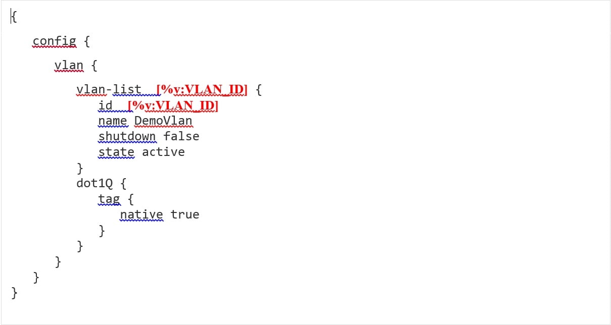
  • VLAN ID

Supported variables in Cisco ASR 9000 Series for L3 Service Extension:

  • VRF Name

  • BGP AS Number

  • Neighbor address

  • Bridge Group

  • Bridge Domain Name

  • BVI

  • NVE interface

Supported variables in Cisco ASR 9000 Series for L2 Service Extension:

  • Bridge Group

  • Bridge Domain Name

  • EVI

  • NVE interface

  • VNI

Editing Templates

You can modify a template that you have created.

Procedure


Step 1

Go to Templates > Device Template Management or Templates > Device Template Management. The Templates / Device Template Management or the Templates / Overlay Template Management page lists all the templates you have created.

Step 2

Select the check box corresponding to the template you need to edit, and click the edit icon.

Note 

Click Edit Configuration button to edit a template.

Step 3

Make the desired changes, then click Review to view the configuration summary for the device. It opens the Review modal and also processes dry-run/preview config call in the backend simultaneously and you can see spinning wheel on modal. Once done, it displays the ‘Review’ modal window. Click on the accordion icon/Template name/device name row will display the configs differences, if any.

Note 
Review button is enabled on device/overlay template pages only if template has at least one device attached to it.
Step 4

Click Save Template.

Note 
If user wants to edit last route target of that combination of direction and type, then user needs to add the new route target of same combination. Go back to edit mode and delete the old pair of route template and save the template.

Copying a Template

You can copy a template and save it with a different name. You can also modify the parameters while you copy.

Procedure


Step 1

Go to Templates > Template Management. The Templates / Template Management page lists all the templates you have created.

Step 2

Select the check box corresponding to the template you need to copy, and click the copy icon.

Step 3

Modify the details if required, then click Save.


Deleting Templates

You can delete a template that you have created.

Note

You can delete a template only if it is not attached to either a tenant or router. If it is attached to a tenant or router, an error is displayed when you try to delete. You need to detach the template from tenant or router before deleting the template.

Procedure


Step 1

Go to Templates > Template Management. The Templates / Template Management page lists all the templates you have created.

Step 2

Select the check box corresponding to the template you need to delete, and click the Delete (X).

The Delete popup appears.

Step 3

Click Delete (X) to delete the template.


Importing and Exporting Templates

You can import and export Cisco VTS device templates and overlay templates.

If you have master templates created on a Cisco VTS lab instance, these can be exported to an external server. Modifications pertaining to the Cisco VTS production instance can be done on the server, and then the templates can be imported on the production instance. This helps you to avoid creating similar templates on multiple production instances.


Note

Templates that are imported into Cisco VTS need to be in the valid JSON format. You might encounter errors if the format is incorrect.


The following sections give details about importing and exporting templates.

Importing Templates

You can import a device templates or overlay templates into Cisco VTS. You can import a single file containing single/multiple device templates at a time. You cannot import templates with names that conflict with existing templates in Cisco VTS .

To import templates:

Procedure


Step 1

Go to Templates > Overlay Template Management or Device Template Management, based on your requirement.

Step 2

Click the Import icon.

Step 3

Locate the template JSON file and click open.

The template file gets imported into Cisco VTS, and is visible in the template list.


Exporting Templates

You can export a device templates or overlay templates from Cisco VTS to an external server. You can export a single or template in bulk.

To export templates:

Procedure


Step 1

Go to Templates > Overlay Template Management or Device Template Management, based on your requirement.

Step 2

Select the templates you want to export.

Step 3

Click the Export icon.

Step 4

Save the template file at the desired location.


Attaching Templates to Routers

You can attach templates to routers while adding a router or while modifying an existing router. By default, router inherits the template from the tenant. You can override an inherited template while you create or modify a router, by selecting a different template, or creating a new template and attaching to the router.


Note

The configuration is pushed to the device only when Port Attach is done. If a router is created and template is applied to the tenant or router, but port is not attached, then the template configuration is not pushed. See Creating a Network using Cisco VTS GUI for details about attaching port.

Attaching Templates while Adding Routers

You can attach L3 Extension templates or Route template while you add a router.

Procedure


Step 1

Click Overlay > Router. The Overlay / Router page is displayed.

Step 2

Click Add (+) icon. The Overlay / Network / Add Router page is displayed.

Step 3

Click the Templates tab. The table displays the L3 extension templates and Route templates you have created for all supported device platforms. The drop-down list lets you display the desired template type for the desired device platform.

Step 4

Select the Template type from Showing drop-down.

Template Type can be L3 Extension or Route.

Step 5

Select the template(s) and click the Attach icon to attach the device(s).

Note 

You can attach only one Route template to devices at a time. If a Route template is already attached and you want to attach a new Route template, then you need to detach the existing Route template. You can attach multiple L3 extension templates to devices.

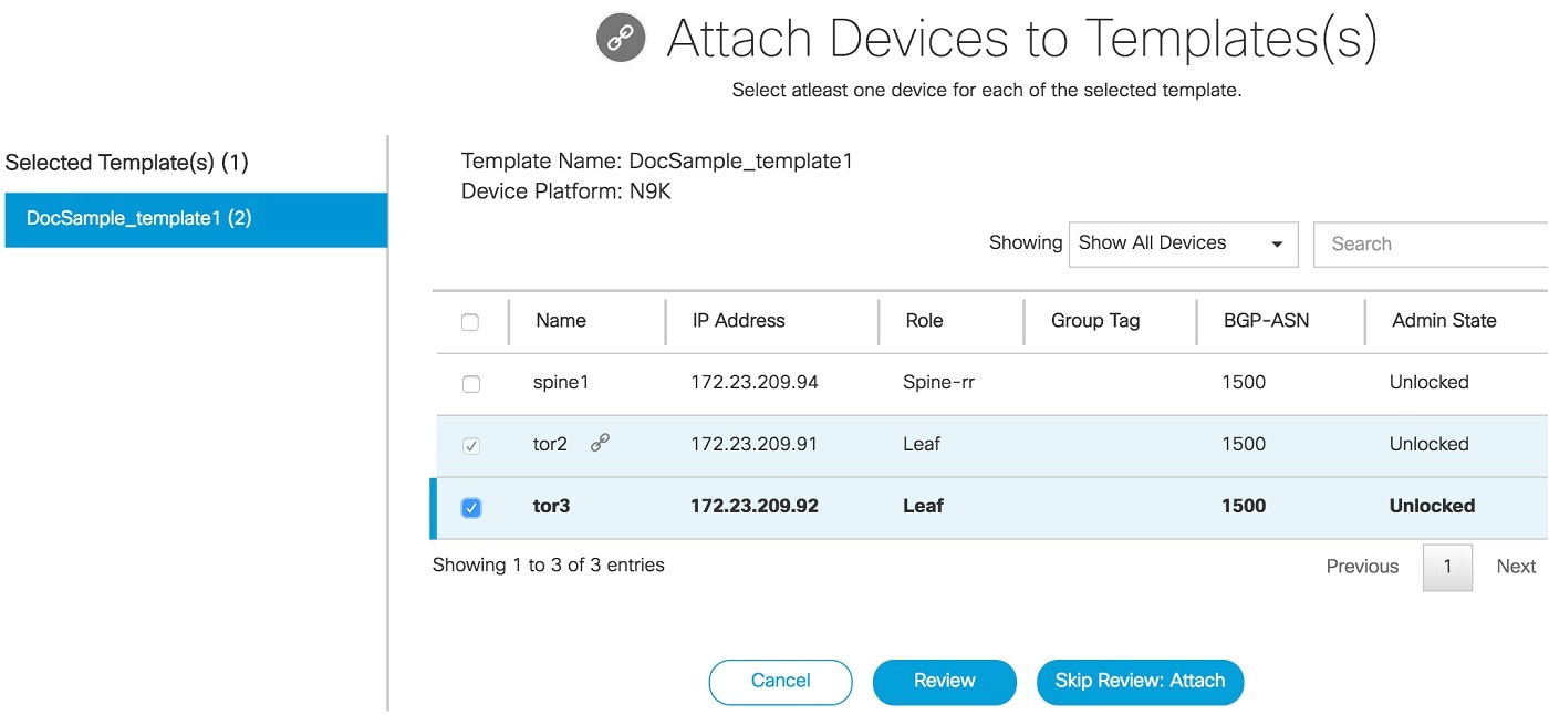
The Attach Devices to Templates(s) page appears with the following details:
  • Template Name

  • Device Platform Name

  • Device Name

  • IP Address

  • Role

  • Group Tag

  • BGP-ASN

  • Admin State

Step 6

Selected templates are listed in the Selected Templates pane. Select the desired template from the list, and then select the device(s) you want to attach.

You may choose to apply the selected templates in bulk to all of the devices, or choose specific devices on which you may want to apply the template.

You can remove the templates that you do not want to attach by clicking the Remove icon.

Step 7

For L3 Extension templates, you can review or skip the review and attach the configuration before you proceed. Select the device(s), then click Review. The review summary popup displays a hyperlink enabled Preview Config option. Click Preview Config link to view config changes in each device.

Note 
This feature is not supported for Route templates.
Step 8

Click Skip Review: Attach to attach the configuration directly to the device.

Step 9

Click Save on the Overlay / Network / Add Router page appears.

Devices added to the templates will be attached to the network.
Note 

You will see Pending Save in Template Status for the changes done, until you do a final save for the devices to be added to the templates.


Attaching Template while Editing a Router

You can attach L3 Extension templates or Route template while you edit a router.

Procedure


Step 1

Go to Overlay > Router. The Overlay / Router page lists all the routers.

Step 2

Select the Router you want to attach the template to, then click Edit icon. The Overlay / Network / Edit Router page is displayed.

Step 3

Click the Templates tab. The table displays the L3 extension templates and Route templates you have created for all supported device platforms. The drop-down list lets you display the desired template type for the desired device platform.

Step 4

Select the Template type from Showing drop-down.

Template Type can be L3 Extension or Route.

Step 5

Select the template(s) and click the Attach icon to attach the device(s).

Note 

You can attach only one Route template to devices at a time. If a Route template is already attached and you want to attach a new Route template, then you need to detach the existing Route template. You can attach multiple L3 extension templates to devices.

The Attach Devices to Templates(s) page appears with the following details:
  • Template Name

  • Device Platform Name

  • Device Name

  • IP Address

  • Role

  • Group Tag

  • BGP-ASN

  • Admin State

Step 6

Selected templates are listed in the Selected Templates pane. Select the desired template from the list, and then select the device(s) you want to attach.

You may choose to apply the selected templates in bulk to all of the devices, or choose specific devices on which you may want to apply the template.

You can remove the templates that you do not want to attach by clicking the Remove icon.

Step 7

For L3 Extension templates, you can review or skip the review and attach the configuration before you proceed. Select the device(s), then click Review. The review summary popup displays a hyperlink enabled Preview Config option. Click Preview Config link to view config changes in each device.

Note 
This feature is not supported for Route templates.
Step 8

Click Skip Review: Attach to attach the configuration directly to the device.

Step 9

Click Save on the Overlay / Network / Add Router page appears.

Devices added to the templates gets attached to the network.
Note 

You will see Pending Save in Template Status for the changes done, until you do a final save for the devices to be added to the templates.


Creating L2 Extension Templates

To create L2 Extension templates:

Procedure


Step 1

Go to Templates > Overlay Template Management. The Templates / Overlay Template Management page appears.

Step 2

Click Add (+). The Create Template page appears.

Step 3

Enter a name for the template in the Template Name field. Only alphabets, numbers, and special characters. , _ and - are allowed. The maximum character limit is 128.

Step 4

Enter a description for the template, in the Description field. This is optional.

Step 5

Choose L2 Extension as the template type.

Step 6

Choose the Device Platform. Currently, the following platforms are supported:

  • Cisco Nexus 9000 Series

  • Cisco ASR 9000 Series

Step 7

Click Add Configuration to add configuration to the template. The Author Template window appears.

Step 8

Click Configuration icon to get the Add Configuration menu. The flyout menu displays all the configuration options that are available at the root level. You can search for the desired configuration in the Search field or configuration items which can take multiple instances, the Add Configurations pane appears in the authoring pane.

Note 

Configuration options available are limited to configuration that Cisco VTS does not provide out of the box. The User Interface(UI) is schema driven and shows the configuration tree based on the device platform selected and the service extension template type, for example, L2 Extension Template. For this release, only configurations under vlan > configuration and vlan > vlan-list are qualified.

Step 9

Choose the desired configuration. The configuration you chose gets added as a child node in the Config tree, on the left pane.

Step 10

Click Add Instance to add an instance. New Instance gets added on the left pane.

For configuration items which can take multiple instances, the Add Instance button appears in the authoring pane. Click Add (+) after you add the configuration for the instance.

Note 

For certain configurations, some of the options that are available for selection have the %v suffix (for example, %vVLAN_ID). The %v suffix denotes that it is a system variable. Here, the vlan-id gets set-up once you associate this particular template at a network level.

The Author Template page provides two types of views:
  • The Editable Tree view—This is the default view.

  • The Read-only Config Preview—Lets you to view a complete summary of the configuration that will be pushed on the device. From the read only view, you can copy the configuration and paste it into any other editor, to view the configuration.

You can toggle between the views using the toggle button on the top right of the config pane.

Step 11

Click Save Template, after you finish adding the desired configuration.


Important Notes—L2 QoS Template

Review the section below before you create QoS template:

  • Policy map has to be created on the devices as part of Day Zero configuration or configured using underlay templates. Only those devices with the service policy map configured will be displayed in the template association UI.
  • Under the vlan configuration Cisco Nexus 9000 supports only service policy with type qos. Both input and output service policies may be configured in the same template.

  • While applying L2 QoS templates, only those devices with the service policy map configured will be shown. The policy map has to be configured on the device for the device to be displayed here.

Important Notes—VPLS Template

Review the section below before you create a VPLS template:

  • Ensure that the necessary Day Zero configuration is complete on the DCI. See Cisco VTS Day Zero Configuration Examples document for details.
  • Create the Admin Domain. Make sure you link the L2GW and DCGW, which is required for L2VNI. See Creating an Admin Domain for details.
  • Create the DCI Interconnect profile with the specific details. See Creating DCI Interconnect Profiles for details.
  • Associate the DCI Interconnect profile to the DCI in the Admin Domain under DCI Interconnect profile tab.
  • Create the L2 Extended Network with an EVI ID assigned to the Network under L2VPN tab. See Creating a Network using Cisco VTS GUI for details.
  • Make sure the subnets and port attach is done for the Network.
  • You can create a template with just PW (pseudo wire) configuration, or just Access VFI configuration, or can have both configurations in one template. Make sure that you enter correct PW and Acess VFI under L2VPN, in the DC that is not managed by VTS.
  • The following are supported as system variables in VPLS templates:

    • Bridge Domain Name
    • Bridge Group Name
    • Interface NVE ID
    • EVI ID

Attaching Devices to L2 Extension Templates

You can attach a device to an L2 Extension template while you create a network, or to an existing network. To attach a device to an L2 Extension template:

Procedure


Step 1

Click Overlay > Network. The Overlay / Network page is displayed.

Step 2

Select the network for which you want to attach the L2 extension template, then click Edit icon.

Step 3

Click the Templates tab. The table displays a list of all L2 extension templates you have created for all supported device platforms. The drop-down list lets you choose the desired device platform.

Step 4

Select the desired template(s), then click the Attach icon.

The Attach Devices to Templates(s) page appears with the following details:
  • Device Platform Name

  • IP Address

  • Role

  • Group Tag

  • BGP-ASN

  • Admin State

Step 5

Selected templates are listed in the Selected Templates pane. Select the desired template from the list, and then select the device(s) you want to attach.

You may choose to apply the selected templates in bulk to all of the devices, or choose specific devices on which you may want to apply the template.

You can remove the templates that you do not want to attach by clicking the Remove icon.

Step 6

For L2 Extension templates, you can review or skip the review and attach the configuration before you proceed. Select the device(s), then click Review. The review summary popup displays a hyperlink enabled Preview Config option. Click Preview Config link to view config changes in each device.

Step 7

Click Skip Review: Attach to attach the configuration directly to the device.

Step 8

Click Save Template .

Devices added to the templates will be attached to the network.
Note 

You will see Pending Save in Template Status for the changes done, until you do a final save for the devices to be added to the templates.


Detaching Devices from L2 Extension Templates

You can detach a device from an L2 Extension template only to an existing network. To detach a device from an L2 Extension template:

Procedure

Step 1

Click Overlay > Network. The Overlay / Network page is displayed.

Step 2

Select the network for which you want to attach the L2 extension template, then click Edit icon.

Step 3

Click the Templates tab. The table displays a list of all L2 extension templates you have created for all supported device platforms. The drop-down list lets you choose the desired device platform.

Step 4

Select the desired template(s), then click the Detach icon.

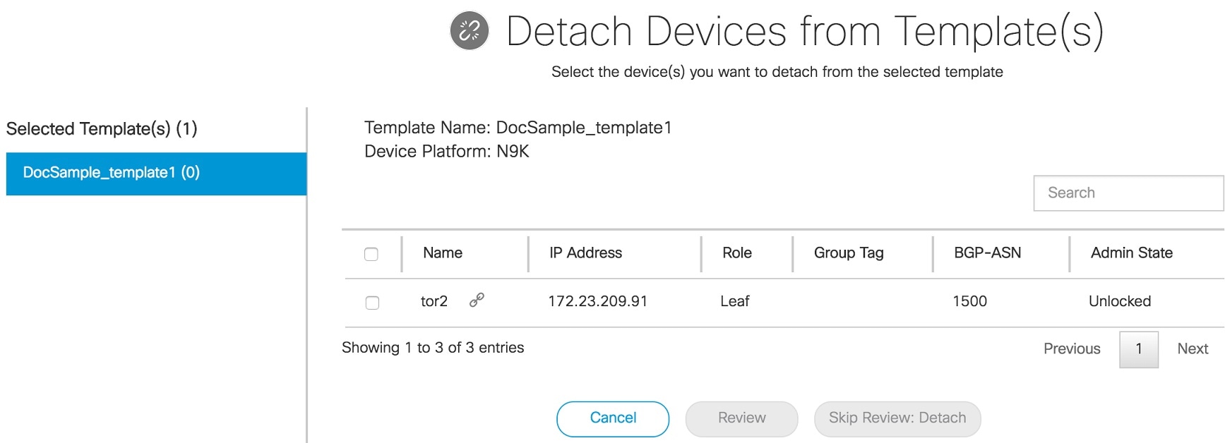
The Detach Devices from Templates(s) page appears with the following details:
  • Device Platform Name

  • IP Address

  • Role

  • Group Tag

  • BGP-ASN

  • Admin State

Step 5

Selected templates are listed in the Selected Templates pane. Select the desired template from the list, and then select the device(s) you want to attach.

You may choose to apply the selected templates in bulk to all of the devices, or choose specific devices on which you may want to apply the template.

You can remove the templates that you do not want to detach by clicking the Remove icon.

Step 6

For L2 Extension templates, you can review or skip the review and attach the configuration before you proceed. Select the device(s), then click Review. The review summary popup displays a hyperlink enabled Preview Config option. Click Preview Config link to view config changes in each device.

Step 7

Click Skip Review: Detach to detach the configuration directly from the device.

Step 8

Click Save Template.

Devices added to the templates will now be detached.
Note 

You will see Pending Save in Template Status for the changes done, until you do a final save for the devices to be added to the templates.


Creating Underlay Templates

To create Underlay templates:

Procedure


Step 1

Go to Templates > Device Template Management. The Templates / Device Template Management page appears.

Step 2

Click Add (+). The Create Template page appears.

Step 3

Enter a name for the template in the Template Name field. Only alphabets, numbers, and special characters., _ and - are allowed. The template name requires at least one alphabet or number. The maximum character limit is 128.

Step 4

Enter a description for the template, in the Description field. This is optional.

Step 5

Choose the Device Platform. Currently, the following platforms are supported:

  • Cisco ASR 9000 Series

  • Cisco Nexus 7000 Series

  • Cisco Nexus 9000 Series

Step 6

Click Add Configuration to add configuration to the template.

The Author Template window appears.

Step 7

Click Configuration icon to get the Add Configuration menu. The flyout menu displays all the configuration options that are available at the root level. You can search for the desired configuration in the Search field.

Step 8

Choose the desired configuration. The configuration you chose gets added as a child node in the Config tree, on the left pane.

You may add further configuration to the node that you have added by clicking the Configuration icon. If you want to delete the configuration, click the Delete (X) icon.

For configuration items which can take multiple instances, the Add Instance button appears in the authoring pane. You can add an instance by clicking Add Instance. Click Add (+) after you add the configuration for the instance.

The Author Template page provides two types of views:
  • The Editable Tree view—This is the default view.

  • The Read-only Config Preview—Lets you to view a complete summary of the configuration that will be pushed on the device. From the read only view, you can copy the configuration and paste it into any other editor, to view the configuration.

You can toggle between the views using the toggle button on the top right of the config pane.

Step 9

Click Save Template.

The template gets added to the Template Management screen. You can click on the template to get a summary of the template, in the Template Summary page. You can expand the Config node to view the template configuration. You can edit the template from the Summary screen, by clicking Edit icon.


Attaching Underlay Template to Devices

To attach an Underlay template to a device:

Procedure


Step 1

Go to Inventory > Network Inventory. The Inventory > Network Inventory page appears.

Step 2

Click Device Templates.

Note 

You can filter templates by Device Platforms.

Step 3

Select the template(s) and click the Attach icon to attach the device(s).

The Attach Devices to Templates(s) page appears with the following details:
  • Template Name

  • Device Platform

  • Device Name

  • IP Address

  • Role

  • Group Tag

  • BGP-ASN

  • Admin State

Selected templates are listed in the Selected Templates pane. Select the desired template from the list, and then select the device(s) you want to attach.

You may choose to apply the selected templates in bulk to all of the devices, or choose specific devices on which you may want to apply the template.

You can remove the templates that you do not want to attach by clicking the Remove icon.

Step 4

Check Devices(s) to attach the devices as per your requirement.

An attach icon is seen adjacent to the devices which have templates already attached.

Step 5

For L2 Extension templates, you can review or skip the review and attach the configuration before you proceed. Select the device(s), then click Review. The review summary popup displays a hyperlink enabled Preview Config option. Click Preview Config link to view config changes in each device.

Step 6

Click Skip Review: Attach to attach the configuration directly to the device.

The devices are successfully attached to the underlay template.


Detaching Underlay Template from Devices

To detach an Underlay template from a device:

Procedure

Step 1

Go to Inventory > Network Inventory. The Inventory > Network Inventory page appears.

Step 2

Click Device Templates.

Note 

You can filter templates by Device Platforms.

Step 3

Select the template(s) and click the Detach icon to attach the device(s).

The Detach Devices from Templates(s) page appears with the following details:
  • Template Name

  • Device Platform

  • Device Name

  • IP Address

  • Role

  • Group Tag

  • BGP-ASN

  • Admin State

Selected templates are listed in the Selected Templates pane. Select the desired template from the list, and then select the device(s) you want to detach.
Note 

You can detach a template only if the Template Status is In use.

You may choose to apply the selected templates in bulk to all of the devices, or choose specific devices on which you may want to apply the template.

You can remove the templates that you do not want to attach by clicking the Remove icon.

Step 4

Check Devices(s) to detach the devices.

Step 5

For L2 Extension templates, you can review or skip the review and attach the configuration before you proceed. Select the device(s), then click Review. The review summary popup displays a hyperlink enabled Preview Config option. Click Preview Config link to view config changes in each device.

Step 6

Click Skip Review: Detach to detach the configuration directly from the device.

The devices are successfully detached from the underlay template.


Previewing Template Configuration

While you attach, detach, or edit an L2 Service Extension or L3 Service Extension, Cisco VTS requires you to preview the template configuration before you proceed with the desired action.

The Review option displays a preview of the configuration summary for each of the devices. The Preview Config link displays the Preview Config Summary popup, which displays the configuration difference that will be pushed on each device. It also shows the timestamp at which the preview was run. The Change Summary gives a count of the number of configuration additions and deletions.

The configuration that is added to the device is shown in Green. The configuration that is removed is shown in Red. A + and - sign shows the additions and deletions respectively. You can click the > icon to get a preview of the configuration.

Preview Config Summary shows the configuration difference for all devices, including devices to which the template was previously attached. Devices to which the template has already been attached will be preselected and grayed out.

The Red out of sync icon indicates that the device is not in sync with the VTS database. You will not be able to attach, detach, or edit a template to the device, if the device is out of sync. You can perform the attach, detach, and edit operations only on those devices which are in sync with the VTS database (as indicated by the Green icon). However, you can still view the configuration difference with the current VTS database, using the drop-down arrow.

You either need to go back and deselect the out of sync device, or you need to go to Network Inventory and sync the device to VTS. Out of sync devices can be synched in Network Inventory

Note

You cannot deselect a device to which the template was previously attached, if the device is currently out of sync with VTS. This is because the UI does not allow you to deselect a device to which the template was already attached. You need to go to Network Inventory and sync the device with VTS before you proceed.


To review the template configuration while you edit a template, at least one device should be attached to the template before you edit the template. Otherwise, the option to review is grayed out.

When you detach a template from a device, the Preview Config Summary shows the configuration difference, which includes the configuration that will be removed from the device upon template detachment, and the additional configuration that Cisco VTS adds to the device.

See Preview Template Configuration Examples to see examples of preview config summary for an attach, detach, and edit operation.

If the template application creates no change in the device configuration, the preview displays No difference.

For L2 Service Extension template, while you attach the template, the configuration summary shows the port configuration and the device configuration. If you have not created ports on a device during network creation, the summary will be shown as No difference for that device. This because the template configuration does not get pushed to the device unless you do a port attach.

For L3 Service Extension templates, the configuration summary shows the interface configuration and device configuration. If an interface is not attached to the Router, the configuration summary will be shown as No difference.

Under certain conditions, for instance, when the commands in the template are invalid, or if the feature is not supported by the device, the summary displays errors.

Preview Template Configuration Examples

The following images show examples of Read-only Config Preview and Preview Config during attach, detach, and edit operations, of an L2 Service Extension template, with ports on two devices, where one device is out of sync.

Figure 1. Read-only Config Preview


Figure 2. Preview Config—Attach Template
Figure 3. Preview Config—Edit Template
Figure 4. Preview Config—Detach Template

Searching Template Content

VTS Templates provide full text search in Overlay Template Management page and Device Template Management page.

Template search enables search on content and configuration across all the templates using solr engine. From VTS UI > Overlay Templates Management and/or Device Templates Management pages, you could enter a "term" in the search box and the Search Results page shows all the templates wherein the term is found either in template name or description or template config.

To perform a template search:

Procedure


Step 1

Go to Templates > Device Template Management or Overlay Template Management. The Templates / Device / Overlay Template Management page appears with a table showing a list of templates.

Step 2

Enter the search text based on your requirement in the Search text box to search across the templates, and press Enter. The / Search Results page appears with the instances of the searched term highlighted.

Step 3

You can refine your search results based on the filters on the left hand side of the search results page. The following filters are available:
  • Category—Filter based on template category, that is, Overlay Templates or Device Template.

    Note 

    If the Category is selected, then template type further refines based on categories (that is, it is dependent). If the Category is not selected, then template type refines based on the type of template.

  • Template Type—Within a category, you can refine the search results based on the template type.

  • Overlay—Filter based on the overlay association—Whether associated to Routers, Networks, or Devices.

Step 4

Click the template name to view the summary page which lists the number of occurrence of the search term in that template.

Step 5

Click on the < or > button adjacent to search term in the summary page to navigate to the instance in the search result. The summary page lists the number of occurrence of the search term in that template config (that is, in config path and config value).

Step 6

Click Export or Edit if you want to export or edit the template.


Using Search Hints

You can search template content using search hints. You can use the following search hints.

Table 1. Using Search Hints

Search Hint

Description

Example

Text

Used for normal text-based search.

Type bgp to search for all strings that match with the term bgp

" "

Used to search complete phrases and IP addresses.

"service extension", "L3_TEMPLATE_N9K", "10.1.1.0/26", "2001:0db8:85a3:0000:0000:8a2e:0370:7334" , "mtu:1500"

AND

Used to search when two terms exist.

Note 
You must type AND in uppercase.

vrf AND bgp

OR

Used to search when either of the term exists.

Note 
You must type OR in uppercase.

vrf OR bgp

NOT

Used to search when you need to exclude terms that are mentioned after NOT.

Note 
You must type NOT in uppercase.

vrf NOT bgp or (vrf AND bgp) NOT ipv6

*

Used for wildcard search.

*—to display all search results swi*—to search for any word that starts with 'swi' virt*tch—to search for any word that starts with 'virt' and ends with 'tch'

?

Used for single character wildcard search.

te?t—to match test, text, and so on.

Creating Device Objects

To create a device object:

Note

VTS 2.6.3 ships with four sample device objects that are read-only. Duplicate these device objects before use.


Procedure


Step 1

Go to Device Objects > Manage.

Step 2

Click + . The Create Device Object popup is displayed.

Step 3

Enter the Name. This is mandatory.

Step 4

Enter a Description.

Step 5

Choose the Device Platform. This is mandatory. Currently, Cisco VTS supports Cisco Nexus 7000 and Cisco Nexus 9000 series devices.

Step 6

Choose the Device Object Type. The supported types are Ethernet and Port Channel.

Step 7

Click Add Configuration. The Author Device Objects page is displayed.

After you pick a particular device object type, port channel for example, only those elements related to port channel get populated in the tree. You cannot delete these elements.

If you want to add more congurations under the device object, you can use the cheese icon to add these.

Under each configuration field, you can choose to enter static values or enter ‘$value’ to get it parameterized. If you choose a particular value to be parametrized you can enter the actual values while you associate the device objects to the device. See Associating Device Objects to Devices for details.

All the mandatory config fields are given '$values' by default and values for any other config fields like shutdown, mtu etc can be provided by the user.

Note 

Channel-group Id under Ethernet configuration is an exception. It is populated with a default '$value' to match with the port-channel Name field.

Step 8

Click Save Device Object. The Device Object gets listed in the Device Objects page. To view a Summary of the device object, click on the Name link. The Summary page shows Device Object Details and the Associations.


Editing Device Objects

To edit a device object:

Procedure


Step 1

Go to Device Objects > Manage.

Step 2

Check the check box adjacent to the device object you need to edit. The Edit Device Object popup is displayed.

Step 3

Edit the Description, if required.

Step 4

Click Edit Configuration. The Edit Device Objects page is displayed.

Make the necessary changes. You need to review the messages that might get displayed based on your changes.

Step 5

Click Save Device Object.

Note 
If device object is already associated with devices, then warning icon appears next to device object in Manage page listing. Also when the Device Object name is clicked, warning icon appears next to the associated devices. The warning icon indicates that the device object instance needs to be edited to update values based on device object edit.

Deleting Device Objects

To delete device objects:

Before you begin

Before deleting the device object, make sure no devices are attached/associated to the device object.

Procedure


Step 1

Go to Device Objects > Manage.

Step 2

Check the check box adjacent to the device object you need to delete.

Step 3

The X icon is enabled.

Step 4

Click X icon to delete the selected device object.


Associating Device Objects to Devices

To associate device objects to devices:

Procedure


Step 1

Go to Device Objects > Associate. The Associate page provides you options to create or delete device objects instances on devices.

Step 2

Select the Device Object you want to attach a device to and click Add Instance. The Add Instance page is displayed.

Step 3

Select a device.

After the device is selected, Device Object Instances are displayed. All fields are not mandatory to be filled. User can skip any '$value' they added during the device-object creation. Any non-substituted values will be skipped on save. The device object config which is static (not parameterized) will appear read-only in this page.

If the same device object is to be attached to a different device, then the procedure has to be repeated.

Summary button is always displayed on Associate page irrespective of devices associated or not.. Edit button is used to exit the summary view and continue with the Add Instance flow.

Review button is enabled only if instance name (base path param name – port-channel name and Ethernet interface name) is filled in for the device object.

Note 

In the case of Port-channel, you can create as many instances as required. In such cases of Device Objects, the Add Instance button is available. To create a new Port-channel Instance, you may click Add Instance button, and the configuration details/values of port-channel config are displayed.

The config which is of type list or collection (e.g. Ethernet) under port channel device object is shown with repetition capability wherein multiple values can be given.

Step 4

Click Review. A review dialog page displays all devices having instance(s) associated with the device objects with an optional Preview Config link on each listed device. The Configuration Summary displays all the configuration that will be pushed to the device. If you want to make any changes, click Back to: Add for any additional information.

Step 5

Click Save to push the configuration directly to the device.


Editing Device Object Instances

To edit a device object instance:

Procedure


Step 1

Go to Device Objects > Associate. The Associate page provides you options to create or edit instance of device objects.

Step 2

Select the Device Object you want to attach to a device and click Edit Instance. The Edit Instance page is displayed.

Only one device and all instances tied to that device can be edited when you initiate this flow.

Step 3

Select a device which was entered earlier.

If you select Edit Instances in the Summary page and initiate this flow, the device is already selected and the instances tied to the device are displayed.

The fields display the values that were set in each of the fields. You can edit any of the fields or add additional instances or delete instances.

Step 4

Click Review. A review dialog page displays all devices having instance(s) associated with the device objects with an optional Preview Config link on each listed device. The Configuration Summary displays all the configuration that will be pushed to the device. If you want to make any changes, click Back to: Add for any additional information.

Step 5

Click Save to apply the changes on device.

Note 

Since the UI takes time to reflect the actual position of the popover, click on the (i) icon or eye icon to open the popover information.


Deleting Device Object Instances

To delete device object instances:

Procedure


Step 1

Go to Device Objects > Associate. The Associate page provides you options to create or edit instance of device objects.

Step 2

Select the Device Object from where you want to delete the instances.

Step 3

Click Edit Instance. The Edit Instance page is displayed.

The fields display the instances associated to the device.

Step 4

Click Delete Instance.

All the instances associated to the selected device can be deleted but only one instance can be deleted at a time when you initiate this flow.


Searching Device Object

VTS 2.6.3 provides full-text search capability for Device Objects. Full-text search enables search on content and configuration across all the Device Objects using solr engine. The Search function is specific to the Device Objects in each site.

From VTS UI > Device Objects, you can enter a term in the Search field. The search result displays all the Device Objects and Device Object Instances that contain the search term in Name or Description or Device Object config.

Follow these steps to perform a Device Object search:

Procedure


Step 1

Choose Device Objects > Manage or Association tab. A list of available Device Objects is displayed.

Step 2

Enter the search text, based on your requirement in the Search all Device Objects field, to search across the device objects, and then press Enter.

The search result displayed splits each Device Object into the two different type of items, namely, Device Object Definition and Device Object Instance. If the search term matches with the configs of the Device Object, the corresponding keypaths are listed after each item.

Note 

If the device object is associated with multiple devices, each device object instance per device is shown in the search results. Device Object Instance name has the following format:

<DeviceObjectName_InstanceType(and)InstanceName_DeviceName>

It displays the device name, device object name along with other metadata of the device.

Step 3

You can refine your search results using the filters on the left pane of the search results page. The following filters are available:

  • Categories: Filters the Device object Instances based on device object definition or device object Instance.

    Note 
    You can refine a category based on the selection.
  • Device Object Type: Filters the Device object based on device object type.

  • Device Object Instance Type: Filters the Device object Instances based on device object instance type.

Step 4

Click the Device Object Name or Device Object Instance name to view the Summary page. The Summary page has the following two tabs:

  • Device Object Details

  • Association Information

The Device Object Details tab displays the number of occurrence of the search term in that entity.

Step 5

Click on the < or > button adjacent to search term on the Device Object Details tab to navigate to the matching configuration in the search result.

The Summary page lists the number of occurrence of the search term in that device object config, namely, in the config path and config value.

Step 6

Click Export or Edit if you want to export or edit the Device Object definition.


Device Objects Notes and Caveats

Following table lists some of the important notes and Caveats for Device Objects.

Table 2. Important Notes and Caveats

Item

Description

Configuration

Using “switch port trunk allowed vlan none” config as part of device template or device object wipes the vlan id configs at later points (redeploy, reconcile and upgrade of services) on device with port attach on same interface. Hence, configure and use it with expected impact in all functional flows. Foe example, Port-attach and then attaching device template will wipe off the vlan id of port attach config.

Sample Device Objects

Four sample device objects (Port-channel DO, Ethernet DO each for N9k and N7k platform types respectively) for read-only from UI are available. If you edit these Device objects from the Manage/Authoring and Associate page, following valid error will be displayed on the UI.

Sample Device Objects cannot be updated.
 Copy Sample Device Object for further usage

Configuration

N7K configurations under "isis" container config should be configured as day0 on device. NED needs to provide the sub-level configs support under "isis" container config. RT#34389.

Sub-config under a config with composite-key

If a normal config (non-composite keys config) contains two $PARAMS of list type in keypath, combination of their (m * n) values given to lists is used to create that many substituted config keypaths to be pushed to device.

In case of config with composite-key that is having a list subconfig, combination cannot be done for the same and should have 1-1 mapping.

For example, Here is the config for “VR and Address family” and addresses within that composite key.

"config/nx:interface/Ethernet{$ETHERNET-NAME}/vrrpv3{$ETHERNET_VRRPV3-VR " "$ETHERNET_VRRPV3-ADDRESS-FAMILY}"

It has sub config of primary addresses (which are of list type)

“config/nx:interface/Ethernet{$ETHERNET-NAME}/vrrpv3{$ETHERNET_VRRPV3-VR $ETHERNET_VRRPV3-ADDRESS-FAMILY}/address/primary-list{$ADDRESS_PRIMARY-LIST-ADDRESS}

If user provides values for $ETHERNET_VRRPV3-VR as 100, 200 and for $ETHERNET_VRRPV3-ADDRESS-FAMILY as ipv4, ipv6 and for ADDRESS_PRIMARY-LIST-ADDRESS as 10.10.10.10, 2001:db8:abcd:0012::0/64

In this case, you cannot do a combination of primary addresses to the composite keys

That is, composite key {100, ipv4} having both the addresses 10.10.10.10 and 2001:db8:abcd:0012::0/64 -- This will not work as address family is ipv4. Hence 1-1 mapping of the list values under composite-key needs to be done so it should look like.

{100,ip4} having just 10.10.10.10
{200,ipv6} having just 2001:db8:abcd:0012::0/64

Currently this creates a limitation that the user cannot supply multiple primary addresses to address family.

Configuration

Device specific behavior: Wherein cleanup is not working properly for vlan ids for Ethernet interface configs with channel-group id referenced in it.

The “switchport trunk allowed vlan <id>” will be pushed to both port-channel and Ethernet interface referencing it. But, while detaching the config “switchport trunk allowed vlan <id>” was not removed from Ethernet interface. You need to enable the “switchport” config in device object definition under port-channel container for the cleanup to work properly on device.

Note 
Device does not reject the config push “switchport trunk allowed vlan <id>” without enable “switchport” config.

Port-channel Ethernet supported config

Under Port-channel device object, the only ethernet config allowed and supported from VTS UI and API is:

         keypath-value "config/nx:interface/Ethernet{$ETHERNET-NAME}" {
            value "{\"Ethernet\": {\"name\": \"$ETHERNET-NAME\", \"shutdown\": \"$SHUT1\"}}";
        }
        keypath-value "config/nx:interface/Ethernet{$ETHERNET-NAME}/channel-group" {
            value "{\"channel-group\": {\"id\": \"$PORT-CHANNEL-NAME\"}}";
        }
        keypath-value "config/nx:interface/Ethernet{$ETHERNET-NAME}/enable" {
            value "{\"enable\": {\"switchport\": \"true\"}}";
        }

CSCvm29427

The Edit instance page shows address with comma separated values for each of the addresses in instance.

Build#13 262 throttle build

Issue: Edit instance page shows address with comma separated values for each of the addresses in instance.

Steps:

  1. Create Ethernet DO type with vrrpv3 and address config under it.

  2. Create 2 instances for above DO on Add instance page and add 2 sets of vrrpv3 configs and attach it to device.

  3. On Edit instance page, we can see address with comma separated values for each of the addresses in instance.

Workaround: Under vrrpv3 Choose address repeater list and then update the address with individual values again in Edit instance page.

CSCvm42414

Configuration

(Preview config behavior of device object in a particular scenario)

Deletion of DO instance does not work if config is updated after config push.

For port-channel device object with ethernet interface associated to it, if “enable -> switchport” config is not set to “true” then vlan id will be pushed only to “port-channel”. Once we update the enable -> switchport” config to “true” then the vlan id is pushed to associated ethernet interface accordingly.

But, when deleting the above port-channel instance device throws invalid command error. Hence, this is expected N9K platform behavior with cleanup of configs as per the sequence of configs pushed.

Work around: Manually disassociate the channel-id from Ethernet interface and then try updating “enable -> switchport” config to default param value, delete the port-channel from UI/API.