- Preface
- Introduction to the Prime Provisioning API
- Getting Started
- Common APIs
- Using Templates
- Monitoring APIs
- MPLS Provisioning
- L2VPN Provisioning
- VPLS Provisioning
- EVC Provisioning
- Traffic Engineering Management Provisioning
- RAN Backhaul Provisioning
- MPLS Transport Profile Provisioning
- GUI to API Mapping
- Implementing a Notification Server
- Scripts
- Prime Provisioning XDE SDK
Cisco Prime Provisioning API Programmer Guide, 7.1
Bias-Free Language
The documentation set for this product strives to use bias-free language. For the purposes of this documentation set, bias-free is defined as language that does not imply discrimination based on age, disability, gender, racial identity, ethnic identity, sexual orientation, socioeconomic status, and intersectionality. Exceptions may be present in the documentation due to language that is hardcoded in the user interfaces of the product software, language used based on RFP documentation, or language that is used by a referenced third-party product. Learn more about how Cisco is using Inclusive Language.
- Updated:
- December 3, 2014
Chapter: L2VPN Provisioning
L2VPN Provisioning
To provision L2VPN using the Cisco Prime Provisioning API, you need an L2VPN service policy of a specific subtype and an L2VPN service request.
The service policy (defined in a service definition) specifies the attributes common to the end-to-end wires and attachment circuits (ACs).
The service request defines the device interfaces for each end-to-end wire connection (called link endpoints in the GUI), and can optionally override policy attributes in each end-to-end wire link and AC.
When you deploy an L2VPN service request using a service order, the attributes specified in the service definition are applied to the devices and interfaces listed in the service request, along with the attributes for each end-to-end wire link and AC.
This chapter describes L2VPN service concepts and the steps required to provision L2VPN services using the Prime Provisioning API. The provisioning example includes the process flow from creating the inventory to auditing the service deployment.
For more information on L2VPN provisioning using Prime Provisioning, see the Cisco Prime Provisioning 7.0 User Guide .
L2VPN Service Definitions
An L2VPN service definition specifies the policy subtype, the properties for the CPE and PE devices, and the user network interface (UNI). The properties that can be set are based on the policy subtype that is specified in the service definition.
As there are a number of L2VPN naming conventions in use today, it is recommended that you read the appendix on Prime Provisioning Layer 2 VPN Concepts in the Cisco Prime Provisioning 7.0 User Guide .
Supported Service Definitions
Prime Provisioning supports the following L2VPN service definition subtypes:
- EthernetEVCS (Ethernet Virtual Circuit Service)
- EthernetEVCS_NO_CE
- EthernetTLS (Transparent LAN Service)
- EthernetTLS_NO_CE
- ATM (Asynchronous Transfer Mode)
- ATM_NO_CE
- FRAME_RELAY
- FRAME_RELAY_NO_CE

Note For all service definition subtypes with NO_CE, you do not declare the CE devices to be CPEs, and you do not set policy attributes for the CE devices in the service definition.
A service definition can be shared by one or more service requests that have similar requirements. L2VPN service definitions include the following information about the end-to-end wires and attachment circuits:
- Service definition subtype (examples: EthernetEVCS or ATM_NO_CE)
- Device interface type (example: GigabitEthernet)
- VLAN IDs
- UNI Port Security
- Protocols (examples: CDP, VTP)
Note For each service definition property, you can set an additional attribute, editable=true, to allow the network operator to override these attributes when creating the service request. If an attribute is set to editable=false, these attributes cannot be changed in the service request.
ATM Policy
In this example, an L2VPN ATM policy is created in a NPE-CE setup with TransportMode, PWClass, ELine name, and L2vpn Group name attributes, which are configured on an IOS XR device.
XML file in Cisco Prime Provisioning API 7.0 Programmer Reference: CreateL2VPNServiceDefn_ATM_PortMode_PWClass.xml
ERS Policy
In this example, an L2VPN point-to-point Ethernet Relay Service (ERS) policy is created in a NPE-UPE-CE setup, where the NPE is an IOS XR device and others are IOS devices.
Here, the PWClass, ELine name, and L2vpn Group name attributes are configured on IOS XR (NPE).
In addition, the Std UNI attributes are configured on IOS (UPE).
XML file in Cisco Prime Provisioning API 7.0 Programmer Reference: CreateL2VPNServiceDefn_EVCS_NBIEnhance_PWClass.xml
L2VPN Service Requests
An L2VPN service request specifies the service definition, assigns device interfaces for the end-to-end wire connections, and the attachment circuit details.
End-To-End Wires
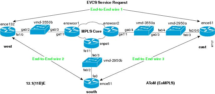
An end-to-end wire is the link from one endpoint through the service provider cloud to another endpoint. In most cases, these links are from CE to CE. An attachment circuit is the link from the CE to the PE. If no CE is present, the attachment circuit link is from PE-CLE to PE-CLE.
In the EthernetEVCS network example shown in Figure 7-1, End-to-End wire 1 is shown from ence132 to ence61. The two attachment circuits are the links from ence132 to enswosr1 and from ence61 to enswosr2.
Figure 7-1 End to End Wire Network Example
The number of end-to-end wires and attachment circuits that can be created are based on the policy subtype.
There can be one or two AttachmentCircuits for every EndToEndWire for the following policy subtypes:
There are 2 AttachmentCircuits for every EndToEndWire for the following policy subtypes:
ATM Service Request
In this example, an L2VPN ATM service request is created in a NPE-CE setup with TransportMode, PWClass, ELine name, and L2vpn Group name attributes, which are configured on IOS XR device.
XML file in Cisco Prime Provisioning API 7.0 Programmer Reference: CreateL2VPNServiceOrder_ATM_PortMode_PWClass.xml
ERS Service Request
In this example, an L2VPN point-to-point Ethernet Relay Service (ERS) service request is created in a NPE-UPE-CE setup, where the NPE is an IOS XR device and others are IOS devices.
Here, the PWClass, ELine name and L2vpn Group name attributes are configured on IOS XR (NPE).
In addition, the Std UNI attributes are configured on IOS (UPE).
XML file in Cisco Prime Provisioning API 7.0 Programmer Reference: CreateL2VPNServiceOrder_EVCS_NBIEnhance_PWClass.xml
Provisioning Example
This section describes the required steps for using the API to provision L2VPN, and includes the operation, class, and required parameters for each step.
Process Summary
In this L2VPN provisioning example, the following steps are listed:
1. Create device groups (optional).
3. Collect device configurations.
10. Declare devices as CPEs (not required for No_CE service subtypes).
11. Create named physical circuits.
15. Create PseudowireClass (optional).
16. Create the L2VPN service definition (policy).
17. Create the L2VPN service request.
Note For clarity, this provisioning process shows each step as a separate XML request. Many of these steps can be combined using performBatchOperations.
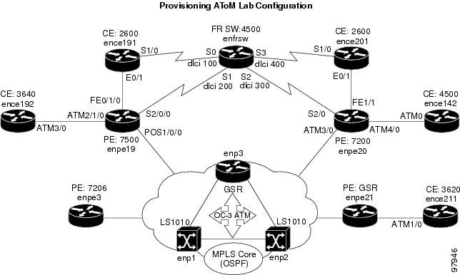
The provisioning example in this section is based on the partial network diagram shown in Figure 7-2.
Figure 7-2 L2VPN Provisioning Network Example
Prerequisites
For security reasons, Prime Provisioning requires the virtual terminal protocol (VTP) to be configured in transparent mode on all switches involved in Ethernet Relay Service (ERS) or Ethernet Wire Service (EWS) before provisioning L2VPN service requests.
To set the VTP mode, enter the following Cisco IOS commands:
Enter the following Cisco IOS command to verify that the VTP has changed to transparent mode:
RBAC
Prime Provisioning uses a Cisco role-based access control (RBAC) product for user login and logoff. These user roles and permissions are set up using the GUI.
When you establish an API session, you are given a session token during the login. For each API XML request, the session token is verified against the RBAC processor to ensure that the API user has permissions for that operation. If the user does not have permissions, the API returns an error.
See the Cisco Prime Provisioning 7.0 User Guide for information on setting up user roles and permissions.
Provisioning Process
This section provides a sample provisioning process using XML examples. The inventory of XML examples for the Prime Provisioning API are available at: Cisco Prime Provisioning API 7.0 Programmer Reference .
Step 1 Create device groups (optional).
In this example, one device group is created for the customer, and one for the provider.

Tip If you plan to create device groups, create the empty device groups before you create the devices. As you create each device, add the associated device group name as a key property in the create device XML request.
In the following example, the device group (CustDev) is added as a key property when creating the device CiscoRouter:
Every network element that Prime Provisioning manages must be defined as a device in the system. An element is any device from which Prime Provisioning can collect information. In most cases, devices are Cisco IOS routers and Catalyst switches.
In this example, an XML request is created for each device in the CPE to PE link, as shown in Figure 7-2.
Step 3 Collect device configurations.
A device configuration collection is a task. This task uploads the current configuration from the device to the Prime Provisioning database. The collection task is executed through a service request, and the service request is scheduled through a service order.
In this example, device collection is divided into two separate tasks. One task performs a configuration collection on the devices in the customer device group, and the second task is for the provider device group. (Device groups were created in Step 1.)
Note To perform a collection on a device group, specify the DeviceGroup keyword in the ServiceRequestDetails. (For example, DeviceGroup=Group_CustDev, DeviceGroup=Group_ProvDev).
The provider is the administrative domain of an ISP, with one BGP autonomous system (AS) number. The network owned by the provider is called the backbone network. If an ISP has two AS numbers, you must define it as two provider administrative domains.
Each provider can contain multiple regions. In this example, an XML request is created for each region.
Step 6 Declare devices as PEs.
The XML request that assigns a PE role (PE-POP or PE-CLE) to a device is also used to:
In this example, an XML request is created for each device to be declared as a PE. Using Figure 7-2 for reference, enpe21=PE1 and enpe20=PE2.
Create an access domain for Ethernet-based services where Prime Provisioning automatically assigns a VLAN for the link from the VLAN pool. Select all PE-POP devices to be associated with this domain, and later in the process, when VLAN pools are created for an Access Domain, the PE-POP is automatically assigned a VLAN ID.
A customer is a requestor of VPN services. Each customer can contain multiple customer sites. Each site belongs to only one customer and can contain many CPEs.
Create sites and assign customers (Organizations) to them. In this example, an XML request is created for each site.
Step 10 Declare devices as CPEs.
The XML request that assigns a CPE to a site is also used to specify:
- The management type.
- CE interface information. If no CE is present, specify the UNI (PE-CLE or PE-POP) interface information.
In this example, an XML request is created for each device you want specified as a CPE. Using the network diagram for reference, ence142=Cpe1 and ence211=Cpe2.
Step 11 Create Named Physical Circuits.
Create an NPC for each physical link in the CPE to PE-POP end-to-end wire. If there are intermediate devices, those links must also be added to the NPC using PhysicalLink.
When creating an NPC, the source device of the first physical link should be the CPE or, in the case of an unmanaged CPE, the U-PE
The PE-POP or N-PE should be the destination device of the last physical link, and any intermediate devices appear twice, first as the destination device of a link, then as the source device of the next link.
- CreateNamedPhysicalCircuit.xml
- CreateNamedPhysicalCircuitRing.xml—Use this example if there is a ring topology configuration on the PE-CLEs.
- CreateNamedPhysicalCircuitRingExisting.xml—Use this example to reference an NPC ring that has already been created.
Create a VLAN ID pool, specify a range, and associate it to an access domain to manually enter the parameters for a VLAN pool. To have Prime Provisioning automatically assign VLANs to end-to-end wire links, specify the AutoPickVlanId keyword in the service definition (see Step 15).
A VC ID pool is global and not associated with a provider or organization.
A VPN in an L2VPN network is only a name used to group L2VPN links.
Step 15 Create PseudowireClass (optional)
Configure a Pseudowire class with the required attributes. This allows Prime Provisioning to configure a Pseudowire class and preferred path on IOS XR devices.
Step 16 Create the L2VPN service definition (policy).
A service definition is a template of the parameters needed to define an L2VPN service request. Once you define the policy template, it can be used by all L2VPN service requests that share a common set of attributes.
Certain properties in the service definition can set an additional attribute, editable=true. This allows the service request creator to change the values on specific policy attributes. If the property is set to editable=false, the service request creator cannot change the policy attributes. See the following example:
In this example, a service definition is created, with a SubType=ATM, and policy attribute values for the Cpe, PE, and UNI with the ServiceDefinitionDetails.
Note If you set the AutoPickVlanId keyword in the ServiceDefinitionDetails, be sure that an access domain is attached to the PE that the PE-CLE (switch) is connected to, and a VLAN pool is assigned to the access domain.
- CreateL2VPNServiceDefn_EVCS.xml
- CreateL2VPNServiceDefn_EthernetEVCS_NO_CE.xml
- CreateL2VPNServiceDefn_EthernetTLS.xml
- CreateL2VPNServiceDefn_EthernetTLS_NO_CE.xml
- CreateL2VPNServiceDefn_ATM.xml
- CreateL2VPNServiceDefn_ATM_NO_CE.xml
- CreateL2VPNServiceDefn_FRAME_RELAY.xml
- CreateL2VPNServiceDefn_FRAME_RELAY_NO_CE.xml
Step 17 Create the L2VPN service request.
An L2VPN service request consists of one or more end-to-end wires, connecting various sites in a point-to-point topology. When you create a service request, you enter several parameters, including the service definition to use, the specific interfaces on the CPE (or UNI) and PE devices, routing protocol information, and IP addressing information.
In this example, an L2VPN service request is created for an ATM network with the CE present. The service request is deployed through a service order. The ServiceRequestDetails specify the attributes for the end-to-end wires and attachment circuits.
Note The service request name must be unique for each NBI API.
|
Note See the “Templates in a Service Request” section. |
Tip Record the LocatorId value that is returned for the service request. The Locator ID is required to perform a configuration audit of the service request.
- CreateL2VPNServiceOrder_EVCS.xml
- CreateL2VPNServiceOrder_EVCS_NO_CE.xml
- CreateL2VPNServiceOrder_EthernetTLS.xml
- CreateL2VPNServiceOrder_EthernetTLS_NO_CE.xml
- CreateL2VPNServiceOrder_ATM.xml
- CreateL2VPNServiceOrder_ATM_NO_CE.xml
- CreateL2VPNServiceOrder_FRAME_RELAY.xml
- CreateL2VPNServiceOrder_FRAME_RELAY_NO_CE.xml
Auditing Service Requests
A configuration audit occurs automatically each time you deploy a service request. During this configuration audit, Prime Provisioning verifies that all Cisco IOS commands are present and that they have the correct syntax. An audit also verifies that there were no errors during deployment by examining the commands configured by the service request on the target devices. If the device configuration does not match what is defined in the service request, the audit flags a warning and sets the service request to a Failed Audit or Lost state.
If you do not want the configuration audit to occur, change the value for the Audit parameter. The Audit parameter supports these values:
- Audit—This is the default. A successfully deployed service request is automatically audited unless this flag is changed.
- NoAudit—Do not perform a configuration audit when the service request is deployed.
- ForceAudit—Perform a configuration audit even if the service request deployment is not successful.
You can use the Audit parameter with a Create, Modify, or Decommission service request or a Deployment task. See the “Service Decommission” section for more information. To perform a configuration audit as a separate task, see the “Configuration Audit” section.
 Feedback