- Overview to Prime Performance Manager
- Managing Gateways and Units Using the CLI
- Managing the Web Interface
- Importing Devices From Other Cisco Prime Applications
- Discovering Devices With Prime Performance Manager
- Managing Users and Security
- Managing Reports, Dashboards, and Views
- Setting Up Reports for Specialized Technologies
- Managing Devices
- Managing Network Alarms and Events
- Creating and Managing Thresholds
- Displaying System Properties, Statuses, Messages, and Logs
- Managing Gateways and Units
- Managing High Availability
- Configuring Prime Performance Manager for Firewalls
- Managing Multi-Tenant Services
- Pushing Prime Performance Manager Data to Other Applications
- Backing Up and Restoring Prime Performance Manager
- Prime Performance Manager and IPv6
- Prime Performance Manager Commands
- Predefined Thresholds
- Compliance
Cisco Prime Performance Manager User Guide, 1.7
Bias-Free Language
The documentation set for this product strives to use bias-free language. For the purposes of this documentation set, bias-free is defined as language that does not imply discrimination based on age, disability, gender, racial identity, ethnic identity, sexual orientation, socioeconomic status, and intersectionality. Exceptions may be present in the documentation due to language that is hardcoded in the user interfaces of the product software, language used based on RFP documentation, or language that is used by a referenced third-party product. Learn more about how Cisco is using Inclusive Language.
- Updated:
- September 28, 2015
Chapter: Managing Reports, Dashboards, and Views
- Displaying Reports
- Exporting Report Data to CSV Files
- Emailing Reports
- Customizing General Report Settings
- Customizing Individual Report Settings
- Customizing Report Aging Settings
- Customizing CSV Export Settings
- Device Report Capability Polling
- Exporting Reports in 3GPP XML Format
- Creating Report Policies
- Displaying Report Definitions
- Sharing Report and Dashboard URLs
- Managing Dashboards
- Creating and Managing Custom Report Views
- Creating and Managing Report Groups
- Creating Web Reports
Managing Reports, Dashboards, and Views
Prime Performance Manager provides over 7200 reports and dashboards covering many different network device hardware and software elements. You can change how report data is displayed, enable and disable reports, and create customized report policies for specific devices or groups of devices. In addition, you create your own custom report views and groups. These and other report features and functions are described in the following topics:
- Displaying Reports
- Exporting Report Data to CSV Files
- Emailing Reports
- Customizing General Report Settings
- Customizing Individual Report Settings
- Customizing Report Aging Settings
- Device Report Capability Polling
- Exporting Reports in 3GPP XML Format
- Creating Report Policies
- Displaying Report Definitions
- Sharing Report and Dashboard URLs
- Managing Dashboards
- Creating and Managing Custom Report Views
- Creating and Managing Report Groups
- Creating Web Reports
Displaying Reports
After Prime Performance Manager device discovery is completed (see Chapter 5, “Discovering Devices With Prime Performance Manager”), you can display reports by either choosing Reports from the Performance menu to display network reports or drill down to a device and display the device reports.

Tip![]() To display an alphabetical list of all provided reports, from the Help menu, choose Reports > Reports List Readme.
To display an alphabetical list of all provided reports, from the Help menu, choose Reports > Reports List Readme.
At the network report level, the following report categories are displayed in the navigation area:
- Application Traffic
- Applications
- Availability
- Compute
- IP Protocols
- IP QoS
- IP SLA
- JMX Applications
- Layer 2 Protocols
- Mobile IOS Statistics
- Mobile StarOS All Counters
- Mobile StarOS CDMA KPI
- Mobile StarOS CDMA Statistics
- Mobile StarOS KPI
- Mobile StarOS Statistics
- NetFlow
- NetFlow AVC
- Network
- Network Services
- OpenStack
- Orchestration
- PPM System
- Resources
- Security
- Small Cell Statistics
- Storage
- Transport Statistics
- Video Broadcast
By default, all reports are disabled except for the following:
–![]() SNMP/Hypervisor Ping Aggregate
SNMP/Hypervisor Ping Aggregate
To enable reports, see Customizing Individual Report Settings.
At the device report level, only the report categories containing reports generated for the device are displayed. As you navigate through Prime Performance Manager reports, keep the following in mind:
- Prime Performance Manager presents reports in a context-sensitive hierarchy. The navigation area is the highest report category level. As you drill down to lower levels, the focus turns to the content area, where you can display detailed reports at specific time intervals. The number of report levels depend on the report category.
- The reports available at any given point depend entirely on the focus. At the network level, the largest number of reports are available because many devices are in focus. As you shift the focus to individual devices, device elements, or to specific report categories, the number of available reports shrinks.
- Report availability ultimately depends upon the hardware and technologies provisioned on the devices. A report will not be displayed for a technology not provisioned on a device.
- Device OS changes, such as upgrades, temporarily stop the report data flow to Prime Performance Manager, particularly for video monitoring. After a device OS change, set the device to its original policy group and do a manual poll.
The device time zone displayed in reports is obtained from one of the following:
- The time zone entered in the device Time Zone field. See Editing a Device Name, Web Port, Time Zone, and Location.
- The device time zone when the device was imported from other applications.
- The time zone retrieved from the device.
- The time zone of the Prime Performance Manager server where the device is connected.
For bulk statistics reports (Moble StarOS Statistics), the following notes apply:
- The time zone displayed for Cisco ASR 5000 and Cisco ASR 5500 devices depends on the bulk statistics file name and header sections. If devices are not configured to send files in the correct formats, the time zone will not display properly.
- The time zone name (EDT, UTC, etc.) is taken from bulk statistics file name. For example: RTPZ5SVCGW02_bulkstats_20120912_113502_EDT_5_5.csv.
- The time zone offset [(+/-)HHMM offset] is taken from the bulk statistics header. For example:
Version-1.6.0,172.18.20.168,20120912-153526,20120912-113526,EDT,-0400,120912-11:35,
private
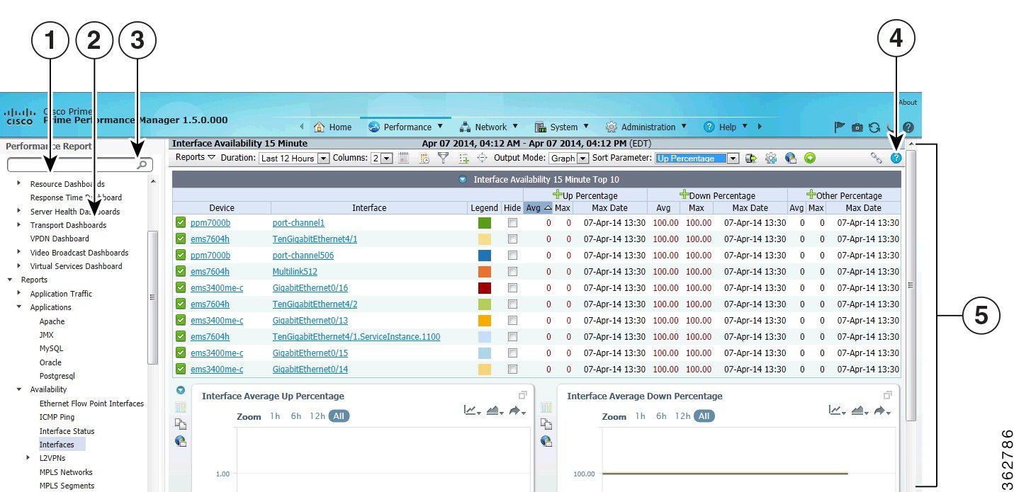
Figure 7-1 shows the Prime Performance Manager reports window with the Interface Availability report displayed in graph output format. Window elements include:
- Navigation tree—Allows you to select high-level report categories and subcategories.
- Search—Allows you to search for reports containing key words. For example, entering “Ethernet” will display all reports with Ethernet in their titles.

Note![]() The Search field is also available from the Views and Dashboards windows.
The Search field is also available from the Views and Dashboards windows.
- Content area—Displays report information. You can switch between graph and table formats by selecting Graph or Table in the reports toolbar Output Mode.
|
|
|
||
|
|
|
||
|
|
|
Reports Menu Bar
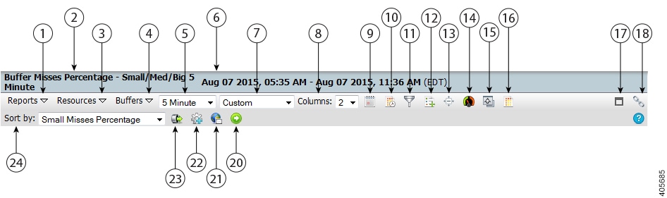
The Prime Performance Manager Reports menu bar allows you change the report presentation in many different ways to meet your personal preferences or to highlight data that is of special interest. The window title bar displays the report name and report period. The report time period shows the time zone in TTT format (where TTT is the time zone, for example, EDT) for all network-level reports when the Display Device Level Data in Device Time Zone user preference is disabled. When the preferences is enabled and the report or dashboard is device level, the time zone is shown in GMT + hh:mm format. The duration is relative to the server or device time zone. For information about setting user preferences, see Customizing the GUI and Information Display.
The tools and options displayed on the reports menu bar depend on whether the output mode. scope, and other factors. Figure 7-2 shows the report toolbar at the device level when output is set to Graph.
Figure 7-2 Reports Menu Bar in Graph Mode
|
|
|
||
|
|
|
||
|
|
|
||
|
|
|
||
|
|
|
||
|
|
|
||
|
|
|
||
|
|
|
||
|
|
|
||
|
|
|
||
|
|
|
||
|
|
|
The menu bar is context sensitive; items that appear depend on the report category and selected report. Menu bar report options include:
- Reports—Allows you to choose the next level report beneath the report level currently in focus. For example, if you choose Availability > MPLS Networks, MPLS availability reports are displayed along with report intervals, for example, hourly, daily, weekly, or monthly.
- Report Subcategory —For report categories with multiple levels, a report subcategory menu is displayed with the subcategory name. The navigation tree, Reports menu, and subcategory menu operate hierarchically; selections vary depending on the depth of the report view in focus.
Note![]() Report subcategories displayed on the report toolbar reflect the subcategories for the displayed report. For example, if you display an hourly temperature report for a device you will see Reports, Resources, and Environment on the toolbar menu because the device temperature is located in the Resources > Environment subcategories. If multiple subcategories exist between Reports and the subcategory containing the report, you will see the first Reports subcategory and the subcategory containing the report.
Report subcategories displayed on the report toolbar reflect the subcategories for the displayed report. For example, if you display an hourly temperature report for a device you will see Reports, Resources, and Environment on the toolbar menu because the device temperature is located in the Resources > Environment subcategories. If multiple subcategories exist between Reports and the subcategory containing the report, you will see the first Reports subcategory and the subcategory containing the report.
- Interval and Duration fields—Two unnamed drop-down lists allow you to choose the report interval and duration. The interval and duration options depend on the report intervals that are enabled. Table 7-1 shows the possible intervals and durations. In the duration field, the terms, past and previous, have distinct meanings:
–![]() Past—Is the specified time unit up to the report query date and time. For example, if Last Hour is specified for a report run at 8:34 AM, the report period would be 7:34 AM to 8:34 AM.
Past—Is the specified time unit up to the report query date and time. For example, if Last Hour is specified for a report run at 8:34 AM, the report period would be 7:34 AM to 8:34 AM.
–![]() Previous—Is the last complete time period before the report query date and time. In this example, the Previous Hour report period would be 7:00 AM to 8:00 AM.
Previous—Is the last complete time period before the report query date and time. In this example, the Previous Hour report period would be 7:00 AM to 8:00 AM.
|
|
|
|---|---|
Custom, last minute, last hour, previous hour, last 6 hours, work shift, today, last 24 hours, yesterday Note Custom uses the time period defined using the Customize Date and Time Range tool. Work shift uses the time period defined in system settings. See Changing System Configuration Settings. |
|
Custom, last 5 minutes, last hour, previous hour, last 6 hours, work shift, today, last 24 hours, yesterday, last 3 days |
|
Custom, last 15 minutes, last hour, previous hour, last 6 hours, work shift, last 12 hours, today, last 24 hours, yesterday, last 3 days, last 7 days |
|
Custom, last hour, work shift, last 12 hours, today, last 24 hours, yesterday, last 3 days, this week, last 7 days, previous week, last 14 days |
|
Custom, yesterday, this week, last 3 days, last 7 days, previous week, last 14 days, last 21 Days, this month, last 30 days, previous month, last 60 days, last 90 days |
|
Custom, previous week, last week, last 4 weeks, last 8 weeks, last 12 weeks, last 6 months, this year, last 1 year, previous year |
|
Custom, previous month, last month, last 3 months, last 6 months, this year, last 1 year, previous year |
Note![]() Intervals greater than the reporting aging intervals will not be displayed. For information, see Customizing General Report Settings.
Intervals greater than the reporting aging intervals will not be displayed. For information, see Customizing General Report Settings.
Tip You can enable the Show One Graph Column Per Report user preference to display all reports as one column per graph. This can be useful if you have device configurations with long index component names that result in long titles and legends, or if you prefer viewing one stacked list of graphs. This preference sets the default. You always change it using the Columns parameter.
- Customize Date and Time Range—Allows you to create a report with a custom date and time range. For reports one hour or less in duration, two options are available:
–![]() Specific Days—Allows you to choose a start and end date and time.
Specific Days—Allows you to choose a start and end date and time.
–![]() Daily Repeat—Allows you to set up queries starting and ending at specific times of day. The queries run every day without a start and end calendar date.
Daily Repeat—Allows you to set up queries starting and ending at specific times of day. The queries run every day without a start and end calendar date.
The maximum time span you can specify depends on the report interval:
–![]() Five minute reports—Four days
Five minute reports—Four days
–![]() Fifteen minute reports—Seven days
Fifteen minute reports—Seven days
Note![]() Intervals greater than the reporting aging intervals will not be displayed.
Intervals greater than the reporting aging intervals will not be displayed.
- Daily Comparative Analysis—Allows you to create a report comparing data gathered on the same day(s) and times, for example, CPU usage at 5:00 PM every day. The option is available for daily report intervals or shorter. After you click Daily Comparative Analysis, choose the days of the week and time of day. then click OK. When the report reloads, it filters the report data on the days of week and time of day you selected. If you copy a filtered graph to a view, the filter is applied to the copied graph as well.
After you set the daily comparative analysis filter, the tool is highlighted. To reset it, open the dialog and click Reset. When the report is displayed, the filter is not applied and the tool is not highlighted.
- Filter—Allows you to filter report information based on different criteria. See Filtering Report Information for information.
- Toggle Legends—When Output is set to Graph, turns the graph legend on and off. If turned on, the graph legend appears under each graph displaying the color-coded report items. and the average and maximum data values for each item.
- Toggle Compact Mode—When Output is set to Graph, toggles the display of the Zoom, Aggregate Lines, Graph Styles, and Export Graphs tools displayed inside graphs. Additionally, the graph border is hidden and graph title reduced in size. Using this option reduces the overall size of the graph and is useful when screen real estate is needed.
- One Graph Per Series—When Output is set to Graph and the report is device level, allows you to display all data series as separate graphs. The option is a toggle.
- Go Live—Initiates 15-second, 30-second, or 1-minute polling for device-level reports. For information, see Creating Live Mode Reports.
- Disable Leaf Graph—Appears when you drill down to the report leaf graph level and the leaf graph has multiple data series. For example, you can drill down an Interface Availability report to the interface level and see three outputs: Up Percentage, Down Percentage, and Average Other Percentage. By default, these are displayed on the same leaf graph. To see the data on separate graphs, click Disable Leaf Graph. To display the leaf graph, click Enable Leaf Graph again.
- Change to Table/Graph View—Allows you to display your report in two different ways:
–![]() Graph—(Default) Displays the report in summary table and graph formats. The summary table summarizes each data series by report entity, for example, device, device interface, or other entity. Summary values includes minimum, maximum, average, and current values, the times the minimum and maximum values occurred, and total, standard deviation, and variance values. Not all values are displayed by default. You can display or hide values by enabling or disabling them in User Preferences. See Customizing the GUI and Information Display. The summary table legend allows you match a table row to the graph element. The graph presents report data visually and includes individual data points. By default, ten report items are displayed. (You can change the number of items displayed in User Preferences. You can also customize the graph display. For information, see Customizing Report Display.)
Graph—(Default) Displays the report in summary table and graph formats. The summary table summarizes each data series by report entity, for example, device, device interface, or other entity. Summary values includes minimum, maximum, average, and current values, the times the minimum and maximum values occurred, and total, standard deviation, and variance values. Not all values are displayed by default. You can display or hide values by enabling or disabling them in User Preferences. See Customizing the GUI and Information Display. The summary table legend allows you match a table row to the graph element. The graph presents report data visually and includes individual data points. By default, ten report items are displayed. (You can change the number of items displayed in User Preferences. You can also customize the graph display. For information, see Customizing Report Display.)
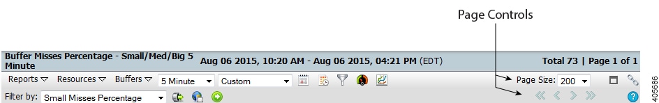
–![]() Table—Displays all report data in table format. Page controls, shown in in the top right control the number of table rows to display. By default, 200 rows per page are displayed. To see all of the data, use the control to page through it, or use the Page Size control to adjust the page size. Figure 7-3 shows the report toolbar in table output mode.
Table—Displays all report data in table format. Page controls, shown in in the top right control the number of table rows to display. By default, 200 rows per page are displayed. To see all of the data, use the control to page through it, or use the Page Size control to adjust the page size. Figure 7-3 shows the report toolbar in table output mode.
Sort Parameter—Allows you to choose a parameter to sort the report information. The parameters displayed depend on the report. For example, in the Figure 7-1 Interface Availability report, the sort parameters are Down Percentage, Up Percentage, and Timeout Percentage.
- Export Report Page as CSV File.—Exports the report to a comma separated values (CSV) file, See Exporting Report Data to CSV Files.
- Graph Series Editor—Opens the Graph Series Editor where you can add, remove, or change the report data series display name in the report graph. Report items are often, but not always, devices. For performance, select no more than ten items. (This option is only available in graph output mode.)
–![]() To change a report data series name, clear the current name in the Display Name field, then type the new name. To remove the custom name and redisplay the system name, click the “ Clear the custom name ” arrow.
To change a report data series name, clear the current name in the Display Name field, then type the new name. To remove the custom name and redisplay the system name, click the “ Clear the custom name ” arrow.
–![]() To delete a series, click the X next to the series item.
To delete a series, click the X next to the series item.
–![]() To add a series, enter the first few letters of the series name in the Add Series field. A list of available items matching the letters you entered is displayed. Click the one you want to add; it is automatically added to the bottom of the data series.
To add a series, enter the first few letters of the series name in the Add Series field. A list of available items matching the letters you entered is displayed. Click the one you want to add; it is automatically added to the bottom of the data series.
When finished, click Run & Close to update the graph with your changes. Other actions:
–![]() Close—Closes the Graph Series Editor and does not save any changes,
Close—Closes the Graph Series Editor and does not save any changes,
–![]() Clear—Removes all content from the Graph Series Editor.
Clear—Removes all content from the Graph Series Editor.
–![]() Reset—Returns the Graph Series Editor to the default data series.
Reset—Returns the Graph Series Editor to the default data series.
- Email Report—Allows you to email the report to individuals of your choosing. For information, see Emailing Reports.
- Run Report—Runs the report after you modify any report parameters in the menu bar.
- Page Link—Retrieves the URL used to launch the selected report from an integrated Cisco Prime application (such as Prime Central), from a Prime Performance Manager Representational State Transfer (REST) client, or on its own in a browser. See Sharing Report and Dashboard URLs for more information.
- Help for Report—Displays a text file with the MIB variables that are polled for generating the report, including any calculations that are performed. This text file also has links to the associated report XML files.
- Sort Parameter—Allows you to sort the report by different parameters.
- Play View—Scrolls through views automatically. The option appears when you display the highest level of your created view. You can change the view interval (20 seconds is the default) and display type (inline or full screen) in User Preferences. For information, see Customizing the GUI and Information Display. For information about views, see Creating and Managing Custom Report Views.
Figure 7-3 shows the reports toolbar when Output is Table. All items pertaining to graphs are removed, and the report length, specified in pages, is shown at the top right. The Page Size option allows you to set the number of table rows displayed in one individual page.
Figure 7-3 Reports Menu Bar in Table Mode
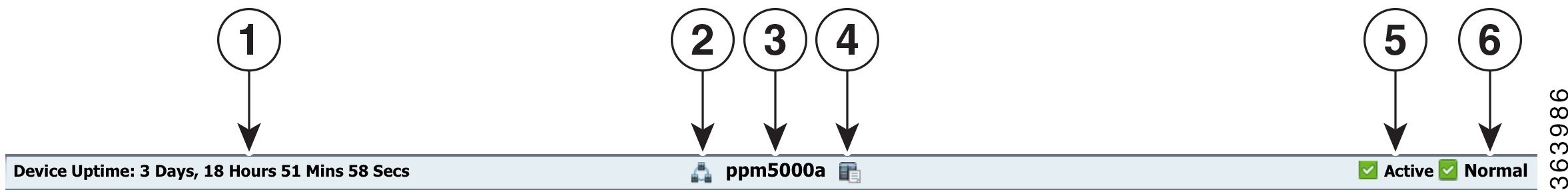
When you drill to a device-level report, a device status bar, shown in Figure 7-4, appears above the report. It shows the device name (center), uptime (left), and the device status and highest alarm on the far right. Two tools are provided allowing you to return to network level view or to display a detailed view of the device.
|
|
|
||
|
|
|
||
|
|
|
Displaying Network and Device Reports
Displaying network and device reports is accomplished using very similar procedures. Prime Performance Manager allows you to easily navigate up and down the report hierarchy, from network-wide views to individual device and device element reports.
Note![]() Network reports include only the devices with report information for the selected report category.
Network reports include only the devices with report information for the selected report category.
To view a network-wide report:
Step 1![]() From the Performance menu, choose Reports.
From the Performance menu, choose Reports.
Step 2![]() In the navigation area, expand the Reports item and choose the report category that you want to view, for example, Application Traffic, Availability, IP Protocols, or other category.
In the navigation area, expand the Reports item and choose the report category that you want to view, for example, Application Traffic, Availability, IP Protocols, or other category.
The content area displays the default network report for the report category you selected. The default report is based on the sort weight assigned to the report. The sort weight is a numeric that indicates the report’s importance relative to other reports in the category. Not all reports are assigned sort weights, however, in which case, reports are arranged alphabetically.
Reports are displayed in graph format by default. For practicality, only ten devices are displayed in graph views by default. If more are available, the report includes Top 10 in the title. To view the other devices, switch to table view or use the Graph Series Editor described in Step 4 to add and remove devices.
To change the number of devices displayed in network device graph view:
- Individual users can change the Maximum Number of Data Series Per Report setting in the User Preferences. (See Customizing the GUI and Information Display.)
- Administrators can set system-wide maximums for all users by changing the Maximum Entries for Top XX Output in the Administration > System Settings window (see Changing System Configuration Settings), or by using the ppm topxxsize command (see ppm tomcatver).
Step 3![]() After you select a report category from the navigation tree, you can:
After you select a report category from the navigation tree, you can:
Note![]() You can change the number of devices displayed in graph view and report summary table using the Maximum Number of Data Series per Report user preference. For information, see Customizing the GUI and Information Display.
You can change the number of devices displayed in graph view and report summary table using the Maximum Number of Data Series per Report user preference. For information, see Customizing the GUI and Information Display.
Note![]() If you drill down to a report, you can refresh it by double-clicking the report category in the navigation tree. For example, if you display Resources > CPU reports, and drill down to the CPU 1 Min Utilization - Device Average Hourly report, to refresh the report, you would double click CPU.
If you drill down to a report, you can refresh it by double-clicking the report category in the navigation tree. For example, if you display Resources > CPU reports, and drill down to the CPU 1 Min Utilization - Device Average Hourly report, to refresh the report, you would double click CPU.
Step 4![]() As needed, perform any or all of the following report modifications by choosing items on the report menu bar (Figure 7-2):
As needed, perform any or all of the following report modifications by choosing items on the report menu bar (Figure 7-2):
- Click the interval and duration fields to choose a different report interval and duration. The duration options depend on the report interval. See Table 7-1 for a list of possible intervals and durations.
- Click Customize Date and Time and choose a custom report start and end date and time. Use this option if the default Duration time periods do not meet your needs. The custom time period can be no longer than seven days.
- Click Report Filter to filter report information. For information, see Filtering Report Information.
- For reports in graph output:
–![]() Click Toggle Legends to turn the graph legend on and off. For reports displayed in graph output, Toggle Legends turns the graph legend on and off. If turned on, the graph legend appears under each graph displaying the color-coded report items and the average and maximum data values for each item.
Click Toggle Legends to turn the graph legend on and off. For reports displayed in graph output, Toggle Legends turns the graph legend on and off. If turned on, the graph legend appears under each graph displaying the color-coded report items and the average and maximum data values for each item.
–![]() Click Graph Series Editor and add or remove devices to and from the report.
Click Graph Series Editor and add or remove devices to and from the report.
Note Graph output provides many other customization options. For information, see Customizing Report Display.)
–![]() Graph (default)—Displays the top N (10 is the default) devices for the selected report in graphical format.
Graph (default)—Displays the top N (10 is the default) devices for the selected report in graphical format.
–![]() Table—Displays all the data for the selected report in table format.
Table—Displays all the data for the selected report in table format.
Note![]() To export the current report page in comma separated values format, click Export report page as CSV file. In table output mode, the entire table is exported to a CSV file. In graph mode, the summary table is exported to a CSV file.
To export the current report page in comma separated values format, click Export report page as CSV file. In table output mode, the entire table is exported to a CSV file. In graph mode, the summary table is exported to a CSV file.
Step 5![]() When finished, click Run Report (green arrow) to run the report with the modified parameters.
When finished, click Run Report (green arrow) to run the report with the modified parameters.
Tip Icons located on each side of the report title allow you to return to network view or explore the device on which the report is based.
Displaying device reports is similar to network device reports, with some navigation and option differences. To display a report for an individual device:
Step 1![]() From the Network menu, choose Devices.
From the Network menu, choose Devices.
All the devices polled by Prime Performance Manager are displayed.
Step 2![]() Click the link of the device that you want to view.
Click the link of the device that you want to view.
The content area displays the default report for the device you selected. The default is based on the sort weight Prime Performance Manager assigns to the report.
Reports are displayed in graph format by default.
Step 3![]() After you display the default device report, you can:
After you display the default device report, you can:
Step 4![]() As needed, perform any or all of the following report modifications by choosing items on the report menu bar (Figure 7-2):
As needed, perform any or all of the following report modifications by choosing items on the report menu bar (Figure 7-2):
- Click the unnamed interval and duration fields to choose a different report interval and duration. The duration options depend on the report interval. See Table 7-1 for a list of possible intervals and durations.
- Click Customize Date and Time and choose a custom report start and end date and time. Use this option if the default Duration time periods do not meet your needs. The maximum custom time periods are:
- Click Report Filter to filter report information. See Filtering Report Information.
- For reports in graph output,
–![]() Click Toggle Legends to turn the graph legend on and off.
Click Toggle Legends to turn the graph legend on and off.
–![]() Click Graph Series Editor and add or remove devices to and from the report.
Click Graph Series Editor and add or remove devices to and from the report.
–![]() The summary table, tools left of the report graph, and all toolbar functions that do not apply to live mode are removed.
The summary table, tools left of the report graph, and all toolbar functions that do not apply to live mode are removed.
–![]() End Live Mode appears at the top of the report window.
End Live Mode appears at the top of the report window.
–![]() Reports are updated continuously every 15 seconds.
Reports are updated continuously every 15 seconds.
–![]() Live mode is displayed in full screen mode,
Live mode is displayed in full screen mode,
For additional information about live mode behavior and requirements, see Creating Live Mode Reports.
–![]() Graph (default)—Displays the top ten data series for the selected report in graphical format.
Graph (default)—Displays the top ten data series for the selected report in graphical format.
Note Graph output provides many other customization options. For information, see Customizing Report Display.)
–![]() Table—Displays all the data series for the selected report in table format.
Table—Displays all the data series for the selected report in table format.
Step 5![]() When finished, click Run the Selected Report (green arrow) to run the report with the modified parameters.
When finished, click Run the Selected Report (green arrow) to run the report with the modified parameters.
Tip Device reports provide View Network Level Report and Explore Device tools next to the report title to allow you to return to the device-level report or to display the device details page at any time.
Customizing Report Display
Prime Performance Manager provides many options to control the report information and how it is presented. The Graph report output provides options that allow you to customize the display to highlight report data or to suit your personal preferences. For example:
- Click Hide Row in a table item—Hides the item from the graph. In addition to Hide Series, clicking the colored boxes in the Graph Legend highlights the associated series in the graph.
- Click a data series name in the legend—Hides/displays the series. (It also grays out the text when the series is hidden.)
- Click Show Graph in Full Screen —Display the graph in full-screen size.
- Click Show Related TCAs —If thresholds are created, displays the threshold in graphical format. If a threshold is not provisioned, the tool is inactive. For information about creating thresholds, see Creating Thresholds.
Note![]() To display threshold on graphs, the threshold must be created in Graph mode.
To display threshold on graphs, the threshold must be created in Graph mode.
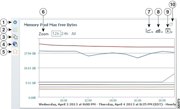
- Click different report time intervals on the Zoom tool
- Click Copy to Clipboard —Copies the graph to a clipboard that is unique for each user on the server. You can copy multiple graphs to the clipboard. The clipboard retains graphs copied to it until you paste the clipboard contents to a custom view page. See Creating a Custom Report View.
Tip Perform the copy and paste operations in two tabs. In one tab, drill through the reports and click the graphs you want. In the other tab, you can paste the items directly into the view you want.
- Click Add to Star Graphs to add the report graph to the Star Graphs tab. See Creating Custom Device Star Graphs for information.
Inside the graphs are tools you can select to modify the graph display:
–![]() Average—Displays the average of all data series in the graph.
Average—Displays the average of all data series in the graph.
–![]() Total—Displays the total of all data series in the graph.
Total—Displays the total of all data series in the graph.
–![]() 95 Percentile—Displays the 95th percentile of all data series in the graph.
95 Percentile—Displays the 95th percentile of all data series in the graph.
–![]() Forecast Values—Displays a dotted line showing projected data values based upon the date entered in the Configure Forecast Data field. The projected data is based on the graph intervals. If the graph is hourly, the projected data will be hourly. If the graph interval is daily, the projected data will be daily. This feature can be used to predict (based on past trends) when an interface or other network object will reach 100% utilization, for example, or other network data trends. Like the other aggregate lines, click once to display the Forecast Values line, click again to hide it.
Forecast Values—Displays a dotted line showing projected data values based upon the date entered in the Configure Forecast Data field. The projected data is based on the graph intervals. If the graph is hourly, the projected data will be hourly. If the graph interval is daily, the projected data will be daily. This feature can be used to predict (based on past trends) when an interface or other network object will reach 100% utilization, for example, or other network data trends. Like the other aggregate lines, click once to display the Forecast Values line, click again to hide it.
Note Average, Total, 95th Percentile, and Forecast Values are not displayed by default. If you click the option, it changes to blue indicating the line is displayed in the chart.
–![]() Configure Forecast Values—Allows you to configure a date or duration to which you want the Forecast Values data line projected. Clicking this option displays the Forecasting Menu dialog box. It shows the number of sample points currently in the graph, and the number of points that you can project. To enter a forecast, the graph must have a minimum of three data points. You can enter a date or duration three times the number of sample points. For example, if an hourly graph has eight sample points, you cannot enter a date or duration beyond three hours from the last graph date and time. If the interval is days with eight sample points, you cannot enter a date or duration 24 days beyond the last date in the graph.
Configure Forecast Values—Allows you to configure a date or duration to which you want the Forecast Values data line projected. Clicking this option displays the Forecasting Menu dialog box. It shows the number of sample points currently in the graph, and the number of points that you can project. To enter a forecast, the graph must have a minimum of three data points. You can enter a date or duration three times the number of sample points. For example, if an hourly graph has eight sample points, you cannot enter a date or duration beyond three hours from the last graph date and time. If the interval is days with eight sample points, you cannot enter a date or duration 24 days beyond the last date in the graph.
–![]() Configure Y-Axis Values—Displayed when you drill down to a leaf graph, this option allows you to display a second Y axis and assign a data series to it. You can also customize the primary and secondary Y axis ranges. For example, if a KPI is generally between 99.1 and 100. you can change the primary Y axis to 99-101 to provide greater graph display variance over the default 0-100 range. Enabling the secondary Y axis allows you to view a KPI and its raw counters in separate scales. For example, you can display raw counters individually, compare them against the KPI graph, and isolate the counter causing the KPI to be lower than an expected SLA.
Configure Y-Axis Values—Displayed when you drill down to a leaf graph, this option allows you to display a second Y axis and assign a data series to it. You can also customize the primary and secondary Y axis ranges. For example, if a KPI is generally between 99.1 and 100. you can change the primary Y axis to 99-101 to provide greater graph display variance over the default 0-100 range. Enabling the secondary Y axis allows you to view a KPI and its raw counters in separate scales. For example, you can display raw counters individually, compare them against the KPI graph, and isolate the counter causing the KPI to be lower than an expected SLA.
Note The first data series in the leaf graph definition, which is often the KPI itself, always aligns to the left axis. The raw counters align to the right axis.
–![]() Line—Displays data in lines.
Line—Displays data in lines.
–![]() Selected Area—Highlights one series.
Selected Area—Highlights one series.
–![]() Stacked Area—Shades and stacks all series.
Stacked Area—Shades and stacks all series.
–![]() Basic Area—Displays a basic area graph.
Basic Area—Displays a basic area graph.
–![]() Percentage Area—Displays the percentage contribution of each series as a graph area.
Percentage Area—Displays the percentage contribution of each series as a graph area.
–![]() Utilization Area—Displays utilization values of each series as a graph area.
Utilization Area—Displays utilization values of each series as a graph area.
–![]() Toggle Time Bar—Allows you to display a time bar within the graph.
Toggle Time Bar—Allows you to display a time bar within the graph.
–![]() Toggle Vertical Graph Grid—Displays or hides a vertical grid.
Toggle Vertical Graph Grid—Displays or hides a vertical grid.
–![]() Toggle Multiple Axes—In merged graphs, allows you to switch between the axis of each chart. (The option does not appear in single graphs.) For information about merging charts, see Merging Graphs in Views.
Toggle Multiple Axes—In merged graphs, allows you to switch between the axis of each chart. (The option does not appear in single graphs.) For information about merging charts, see Merging Graphs in Views.
–![]() Pie—Displays a pie graph with the average value of each series.
Pie—Displays a pie graph with the average value of each series.
–![]() Percentage Column—Similar to the Percentage Area option, but displayed in columns.
Percentage Column—Similar to the Percentage Area option, but displayed in columns.
–![]() Column—For leaf graphs, that is, for the lowest report level, displays basic bar columns. Not available for other level graphs.
Column—For leaf graphs, that is, for the lowest report level, displays basic bar columns. Not available for other level graphs.
–![]() Stacked Column—Works same as StackedPercentageColumn in report XML but sets chart type to Stacked Column type.
Stacked Column—Works same as StackedPercentageColumn in report XML but sets chart type to Stacked Column type.
–![]() Bar—Displays the average value of each series. The vertical axis is the series list, and the horizontal axis displays the average values of those series for the specified interval.
Bar—Displays the average value of each series. The vertical axis is the series list, and the horizontal axis displays the average values of those series for the specified interval.
–![]() Utilization Column—Displays the utilization of each series as bar sequence.
Utilization Column—Displays the utilization of each series as bar sequence.
–![]() Toggle Logarithmic Axis—Moves the axis to logarithmic scale, that is, displays a quantity value using intervals corresponding to orders of magnitude rather than a standard linear scale.
Toggle Logarithmic Axis—Moves the axis to logarithmic scale, that is, displays a quantity value using intervals corresponding to orders of magnitude rather than a standard linear scale.
–![]() ToggleVertical Graph Grid—Displays vertical grid within the graph.
ToggleVertical Graph Grid—Displays vertical grid within the graph.
Tip Clicking an individual data point in a graph displays the data series summary table view.
Figure 7-5 Graph Display Options
|
|
|
||
|
|
|
||
|
|
|
||
|
|
|
||
|
|
|
You can control the display of report data values through settings in the User Preferences window. For example, you can choose whether you want the minimum, maximum, average, total, current, standard deviation, and variance data values displayed in graphs and summary tables. In other words, for any data item, the minimum value for the report period, maximum value, average, total, current, standard deviation, and variance values can be displayed. In addition, you can enable or disable the graph vertical data point bar, change the graph height, or display only one graph column per report. For information about changing user preferences, see Customizing the GUI and Information Display.
Tip![]() Click the legend color swatches to highlight or not highlight the corresponding series in the graph. Click the legend text to show or hide that series.
Click the legend color swatches to highlight or not highlight the corresponding series in the graph. Click the legend text to show or hide that series.
The time span bar is another option you can use to reduce the time span within a graph so you can view intervals of interest in greater detail. By default, the time span bar is displayed in all full screen graphs. However, it can be enabled so that it appears on all report graphs.
To display the time span bar, click Change Graph Display in the upper right corner of the graph and click Toggle Time Bar to display or hide the time bar. You can also enable it by default by selecting Enable Graph Time Span Bar in User Preferences. These and many other options are provisioned in the User Preferences window. For information, see Customizing the GUI and Information Display.
Creating Live Mode Reports
Prime Performance Manager live mode reports have 15-second, 30-second, or one-minute polling. To start a live mode report, navigate to the device level report and click the Go Live tool on the report toolbar. Live mode reports share presentation and tools with other Prime Performance Manager reports, but have certain unique requirements and behaviors.
First, you can only run live mode for device-level reports. You cannot run it for network, group, and tenant reports, or for reports using CSVPoll, flowPoll, DCMPoll, sysDataMetrics.xml, sysPollerMetrics.xml, and ping.xml. In addition, some reports, such as ICMP Ping, do not support 15-second polling. If live mode polling is not available for a report, the Go Live tool is not displayed in the report toolbar.
When you start live mode polling, an End Live Mode tool appears at the top of the report window. Use this tool to stop live mode polling. Next to End Live Mode is a field that allows you to change the report polling frequency from 15 seconds to 30 seconds or one minute.
Tip![]() Should data not appear to be correct, or if a time out appears in the report, increase the frequency. Time outs occur when the device response time is greater than the selected polling frequency.
Should data not appear to be correct, or if a time out appears in the report, increase the frequency. Time outs occur when the device response time is greater than the selected polling frequency.
You can display live mode reports in table or graph format. However, to change the report format, you must return to the network level report, change the format, then click Go Live to start live mode in the new report format.
Live mode data is saved for three days. Report export (CSV, JPG, PNG, PDF) and display options available for longer-period reports are available for live mode reports. For information, see Customizing Report Display.
Live mode continues as long as you remain on the device page, or until you click End Live Mode. If you move away from the device window to another window, for example if you click the View Network Level Report or Explore Device tools next to the report title, live mode stops. To start it, return to the device report and click the Go Live tool.
Some devices take longer than 15 seconds to poll. If so, Prime Performance Manager sends messages indicating the device is not responding. If the device remains unresponsive, Prime Performance Manager increases the polling interval until it finds an interval that is successful. It attempts each interval two times. If data is not recovered at 1-minute polling, live mode exits.
Creating Custom Device Star Graphs
At the device report level, you can pick individual report or dashboard graphs and add them to the Star Graphs tab to create a customized, device-level report view.
To create a custom device star graph:
Step 1![]() From the Network menu, choose Devices.
From the Network menu, choose Devices.
Step 2![]() Click the link of the device for which you want to create a custom view.
Click the link of the device for which you want to create a custom view.
Step 3![]() From the Reports menu, display the report containing the data you want to add to the custom view. You can also choose a dashboard by clicking Dashboards and selecting a dashboard.
From the Reports menu, display the report containing the data you want to add to the custom view. You can also choose a dashboard by clicking Dashboards and selecting a dashboard.
The report (or dashboard) is displayed in graph output format by default.
Step 4![]() Navigate to the graph that you want to add, and click the Add to Star Graphs tool inside the graph.
Navigate to the graph that you want to add, and click the Add to Star Graphs tool inside the graph.
The graph is automatically added to the Star Graphs tab.
Step 5![]() Repeat Step 4 until you have added the graphs that you want to the Star Graphs tab. You can navigate to different reports (or dashboards) and select graphs from them as well.
Repeat Step 4 until you have added the graphs that you want to the Star Graphs tab. You can navigate to different reports (or dashboards) and select graphs from them as well.
Note![]() For performance, you should add no more than ten graphs to the Star Graphs tab.
For performance, you should add no more than ten graphs to the Star Graphs tab.
Step 6![]() When finished, click the Star Graphs tab to view your custom report view for the device. The tab displays the selected graphs in normal report view. View menu bar (see Figure 7-2) actions are available.
When finished, click the Star Graphs tab to view your custom report view for the device. The tab displays the selected graphs in normal report view. View menu bar (see Figure 7-2) actions are available.
Report items in the Star Graphs view remain until you delete them.
Step 7![]() To remove a report item, click the Remove this Graph toolbar item inside the graph you want to delete. You can also remove a star graph report by unchecking the star of the report on the page where it was first starred.
To remove a report item, click the Remove this Graph toolbar item inside the graph you want to delete. You can also remove a star graph report by unchecking the star of the report on the page where it was first starred.
Filtering Report Information
Prime Performance Manager provides many methods for displaying report information in different ways. Many (but not all) reports display one of the following options:
- Sort by—Provides a second report sorting layer in addition to sorting available through the report data columns. You can effectively sort the report by the data series first, then sort by individual parameters within the data series.
- Filter by/Sort by—Filter by (table reports) and Sort by (graph reports) appear in reports that have many data items, such as small cell reports. The option is a convenience to make sorting the report easier. Choosing a Filter by option sorts the report in descending order by the selected data item.
- Group by—Appears in small cell group reports. It allows you to filter the report by small cell inventory group. Prime Performance Manager creates the groups dynamically based on inventory data retrieved from RMS servers. Selecting None displays all small cell inventory groups,
In addition to sorting and filtering data by report menu bar selections, you can filter report information to display data within specific parameters, for example, to display devices containing certain letters in the device names, or a down percentage KPI higher than a specific number. You can filter reports based on report columns or by groups if groups are defined,
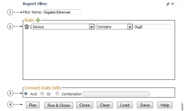
To filter a report, display the report and click the Filter tool on reports toolbar. The Report Filter dialog box, shown in Figure 7-6, allows you to filter reports in one of several ways.
- Enter one or more filter rules then click Filter Report to quickly filter a report.
- Save a filter for future use by entering a filter name in the Filter Name field and clicking Save.
- Load a previously-saved filter by clicking Load Filter. Prime Performance Manager always runs the filter rules currently displayed in the dialog box. You only click Load Filter when:
–![]() No filters are displayed and you want to load a previously-saved filter,
No filters are displayed and you want to load a previously-saved filter,
–![]() A filter is displayed and you want to switch to another saved filter.
A filter is displayed and you want to switch to another saved filter.
Filter rules are added by clicking the Add a New Filter Rule tool. In the Report Filter, shown in Figure 7-6, you can add multiple rules to a filter using the following drop-down fields:
- First drop-down—Lists all filterable report columns plus Device Type and Group Definition items. If you choose a report column, the report is filtered by that column. If you choose Device Type, you can filter the report by device types. If you choose Group Definition, you can filter the report by a defined group. (For more information about groups, see Creating and Managing Report Groups.)
- Second drop-down—Displays the operations permitted for the report column selected in the first drop-down. The available operations depend on the data type of the column selected in the first drop-down:
–![]() Device and Device Type—Equals, Does Not Equals, Begins With, Ends With, Contains, Does Not Contain.
Device and Device Type—Equals, Does Not Equals, Begins With, Ends With, Contains, Does Not Contain.
–![]() Group, String, InetAddress—Equals, Does Not Equals, Begins With, Does Not Begin With, Ends With, Does Not End With, Contains, Does Not Contain.
Group, String, InetAddress—Equals, Does Not Equals, Begins With, Does Not Begin With, Ends With, Does Not End With, Contains, Does Not Contain.
–![]() Float, Timestamp, Double, Integer, Long, Short, Util—Equals, Does Not Equals, Greater Than, Greater Than or Equal To, Less Than, Less Than or Equal To.
Float, Timestamp, Double, Integer, Long, Short, Util—Equals, Does Not Equals, Greater Than, Greater Than or Equal To, Less Than, Less Than or Equal To.
If you choose Group Definition, it displays a list of defined groups. If you choose a group with more than one process item, a fourth drop-down is displayed allowing you to pick the process item to use with the group.
–![]() And—If selected, every rule must apply before results are returned.
And—If selected, every rule must apply before results are returned.
–![]() Or—If selected, only one rule needs to apply before results are returned.
Or—If selected, only one rule needs to apply before results are returned.
–![]() Combination—Allows you to set the rule relationships using a combination of connectors: and, or, not. Examples: 1 and (2 or 3); 1 and not (2 or 3).
Combination—Allows you to set the rule relationships using a combination of connectors: and, or, not. Examples: 1 and (2 or 3); 1 and not (2 or 3).
–![]() Run—Runs the filter against the report but leaves the Report Filter displayed.
Run—Runs the filter against the report but leaves the Report Filter displayed.
–![]() Run & Close—Runs the filter against the report and closes the Report Filter
Run & Close—Runs the filter against the report and closes the Report Filter
–![]() Close—Closes the Graph Series Editor and does not save any changes,
Close—Closes the Graph Series Editor and does not save any changes,
–![]() Clear—Removes all content from the Graph Series Editor.
Clear—Removes all content from the Graph Series Editor.
–![]() Load—Loads a previously saved filter.
Load—Loads a previously saved filter.
–![]() Save—Saves the current filter
Save—Saves the current filter
Figure 7-6 Report Filter Dialog Box
|
|
|
||
|
|
|
Exporting Report Data to CSV Files
You can export Prime Performance Manager report data to CSV files, which you can display in a spreadsheet or database management application for further review and analysis. The data exported depends on the output mode. In Graph mode, the summary table is exported. In Table mode, the detailed data table page is exported.
To export a report to a CSV file:
Step 1![]() From the Performance menu, choose Reports.
From the Performance menu, choose Reports.
Step 2![]() Navigate to the report you want to export to CSV.
Navigate to the report you want to export to CSV.
Step 3![]() On the report toolbar, click Export Report Page as CSV.
On the report toolbar, click Export Report Page as CSV.
Note![]() Report Page only applies to Table view. Only the table page currently displayed is exported. If you want to export all the Table view data, set the page size to the maximum, export each page, then merge the files in your spreadsheet or database application.
Report Page only applies to Table view. Only the table page currently displayed is exported. If you want to export all the Table view data, set the page size to the maximum, export each page, then merge the files in your spreadsheet or database application.
Step 4![]() In the Export Report Columns to CSV dialog box you can do any of the following:
In the Export Report Columns to CSV dialog box you can do any of the following:
- By default, all report columns are selected for export. To remove a column, select it and click Remove. The column moves to Available Columns. To add the column, select it and click Add
- To change the order in which columns appear in the CSV file, select the column and click Move Up or Move Down. Columns at the top appear first in the CSV; columns at the bottom appear last.
- To save the customized columns for future exports, click Save.
- To load a previously-saved column filter, click Load.
- To remove all non-key data fields, click Remove All Data Fields.
Note![]() Columns in bold are the table keys.
Columns in bold are the table keys.
Step 5![]() When finished, click Export to export the data and leave the dialog displayed, or Export and Close to export the data and close the dialog.
When finished, click Export to export the data and leave the dialog displayed, or Export and Close to export the data and close the dialog.
Emailing Reports
You can set up schedules to have Prime Performance Manager automatically email report, view, or dashboard graph image to individuals. The emails can be sent at regular intervals on an ongoing basis, or they can be sent for a set number of times. You can also end the mail one time immediately instead of on a schedule.
To email reports, complete the following procedures:
Creating a Mail Report
You can create report emails for report graphs or tables in the views, dashboards, network or device reports, or star graphs. Creating a report email creates a schedule for sending a report, view, or dashboard graph to individuals by email. Graphs can be included as attachments or embedded in the email in PNG, JPG, GIF, or PDF format.
Step 1![]() Verify the SMTP server is configured for Prime Performance Manager:
Verify the SMTP server is configured for Prime Performance Manager:
a.![]() From the Administration menu, choose System Settings.
From the Administration menu, choose System Settings.
b.![]() In the System Configuration Settings, verify an SMTP server is entered in the SMTP Mail Server field. If not, provision the mail server that Prime Performance Manager should use for outgoing emails. This can be the mail server IP address or host name. In many cases, you can enter localhost. If needed, consult your network administrator.
In the System Configuration Settings, verify an SMTP server is entered in the SMTP Mail Server field. If not, provision the mail server that Prime Performance Manager should use for outgoing emails. This can be the mail server IP address or host name. In many cases, you can enter localhost. If needed, consult your network administrator.
Step 2![]() From the Performance menu, choose Reports, Views, or Dashboards.
From the Performance menu, choose Reports, Views, or Dashboards.
Step 3![]() Navigate to the report containing the graph(s) for which you want to create an email report.
Navigate to the report containing the graph(s) for which you want to create an email report.
Step 4![]() Perform one of the following, depending on what you want to email:
Perform one of the following, depending on what you want to email:
Step 5![]() In the Email Report dialog box, complete the report fields.
In the Email Report dialog box, complete the report fields.
Email Configuration—Provides the email address and subject:
- Email From Address—Enter the email address that you want used as the report sender. This is the address to which replies are sent. You can enter any legitimate email address. However, the intent is for the user creating the report email to enter their email address or an alias to which replies can be sent, for example, ppmreports@mycompany.com.
Note![]() If a global email from address is configured, that address automatically populates the Email From Address field. You can remove or edit the global address, however. The global email from address is configured in Administration > System Settings > System Configuration.
If a global email from address is configured, that address automatically populates the Email From Address field. You can remove or edit the global address, however. The global email from address is configured in Administration > System Settings > System Configuration.
- Email To Addresses—Enter the email address(es) of the individual(s) to whom you want to send the report. The addresses must be legitimate. If you enter multiple addresses, separate the addresses with semicolons and no spaces. You can enter an email alias or list as long as it is recognized by the email server.
- Email Subject—Is the subject line in the email that is sent. It is required. You can enter variables that will list the report and server names in the email subject:
–![]() $server—The gateway server name.
$server—The gateway server name.
For example, if your gateway server is gateway_123, your ReportMail is named SampleReport, and you type $name from $server in the Subject field, the email subject will be SampleReport from gateway_123.
Note![]() $name only applies to scheduled report emails. If you click Send Now, $name is replaced with “current_state” indicating the report email current state is the time you clicked Send Now.
$name only applies to scheduled report emails. If you click Send Now, $name is replaced with “current_state” indicating the report email current state is the time you clicked Send Now.
Output Configuration—Defines the report output and email delivery.
PNG produces the best overall results, depending on the graph complexity, so is the format you should generally use. PDF is not recommended for complex reports or views with multiple graphs, GIF image quality is lower overall.
Note![]() Embed Image, Width, and Height apply only to PNG, GIF, and JPG output formats.
Embed Image, Width, and Height apply only to PNG, GIF, and JPG output formats.
Note![]() The width and height do not guarantee the image size will match exactly. However, the resulting image will generally be close to the width provided and the height will vary depending on the image itself.
The width and height do not guarantee the image size will match exactly. However, the resulting image will generally be close to the width provided and the height will vary depending on the image itself.
Schedule Configuration—Allows you to define a report email schedule:
- Scheduled—If selected, displays fields that allow you to schedule the timeframe and frequency to email the report. If you do not want to schedule the report, you can click Send Now to send the report immediately.
- Name—Allows you to add additional information to distinguish the report when viewed in the Report Mail Editor. Spaces and special characters are not allowed, with the exception of underscores and hyphens, which are allowed.
- Enabled—If checked, enables the email report. If not checked, the email will not be sent. This parameter allows you to create the report and enable it at a later time. You can also disable the report email temporarily at a later point.
- Repeat—Enter the interval at which you want the email report to run:
- Frequency—Sets the number of times the report should run for the selected Recurs Type. For example, if you select a recurs type of hourly and enter a frequency of 4, an email will be sent every four hours. The Start Date and End Date are optional fields that further refine the time that emails are sent. If you enter a start date, no emails are sent prior to that date. Similarly, if you enter an end date, no emails are sent after that date. If you do not enter dates, no date restrictions are applied.
- Start Date—Enter the report start date by clicking the field and choosing the start date from the calendar.
Beneath the Start Date, choose the days you want the report run. The days selected are another way to restrict when emails are sent. If the day is selected, emails are sent. If the day is not selected, no emails are sent.
In other words, all selected criteria must be met for an email to be sent. The day must be selected, the date has to be in range (if dates are specified), the time of day has to be between the times specified (if they are not set to the same time).
Note![]() If both times are set to 0:00, no time of day restriction is applied.
If both times are set to 0:00, no time of day restriction is applied.
Note![]() If the report mail runs near the top of the hour, which is the default, the Prime Performance Manager will not have time to process all the last time interval statistics. If recipients receive an email at, for example, 10:04. The report will include hourly data up to 9:00 but not 10:00 because data collecting and processing takes time. Adding an offset to the start and end times can produce better results. If the report email is scheduled for ten minutes after the hour, time is allocated for the data to be processed. For example, if you set the Start Time and End Time to 12:10, the report mail will run at 10 minutes after the hour, every hour and have sufficient time to collect statistics for the 10:00-11:00 interval.
If the report mail runs near the top of the hour, which is the default, the Prime Performance Manager will not have time to process all the last time interval statistics. If recipients receive an email at, for example, 10:04. The report will include hourly data up to 9:00 but not 10:00 because data collecting and processing takes time. Adding an offset to the start and end times can produce better results. If the report email is scheduled for ten minutes after the hour, time is allocated for the data to be processed. For example, if you set the Start Time and End Time to 12:10, the report mail will run at 10 minutes after the hour, every hour and have sufficient time to collect statistics for the 10:00-11:00 interval.
Step 6![]() Perform one of the following:
Perform one of the following:
The report is added to the Network Report Mail Editor screen. To view it, from the Network menu, choose Report Mail Editor.
Managing Mail Reports
You can manage mail reports from the Network Report Mail Editor. The editor displays all the mail reports that have been created in Prime Performance Manager and allows you to view, edit, enable, disable, and delete individual reports.
Step 1![]() From the Network menu, choose Report Mail Editor.
From the Network menu, choose Report Mail Editor.
Step 2![]() The Network Report Mail Editor displays the following information for each mail report:
The Network Report Mail Editor displays the following information for each mail report:
The Report URL provides a link you can click to view the report. For other parameter descriptions, see Creating a Mail Report.
Tip Hovering over a row with your mouse displays a tool tip that shows the text entered in the Subject field when you created the scheduled the email.
Step 3![]() To enable, disable, or delete one or more email reports:
To enable, disable, or delete one or more email reports:
a.![]() Choose the email report(s) that you want to enable, disable, or delete. (To choose multiple thresholds, press the Shift key to select contiguous thresholds, or Ctrl to choose noncontiguous thresholds.
Choose the email report(s) that you want to enable, disable, or delete. (To choose multiple thresholds, press the Shift key to select contiguous thresholds, or Ctrl to choose noncontiguous thresholds.
b.![]() From the Actions menu, choose Enable Selected Report Mails, Disable Selected Report Mails, or Delete Selected Report Mails.
From the Actions menu, choose Enable Selected Report Mails, Disable Selected Report Mails, or Delete Selected Report Mails.
Prime Performance Manager will update the email report information.
Step 4![]() To perform other email report actions, from the Action column, perform any of the following:
To perform other email report actions, from the Action column, perform any of the following:
The Duplicate Report Mail dialog appears. All entries are identical to the original report, but “_duplicate” is appended to the report name. Edit any parameter, including the provided default name, which must be should be unique, then click OK to create the new report. For parameter descriptions, see Creating a Mail Report.
Customizing General Report Settings
You can provision report intervals and report aging parameters and apply them to all Prime Performance Manager reports from the Performance > Reports > Administration Report Settings window. The master report settings allows you to set up the broad rules for report generation and management. These rules can be overridden at the individual report level, for example, you might decide not to enable 1-minute reports as a global setting, but enable 1-minute reports for certain critical areas.
To provision the master report general and aging settings:
Step 1![]() From the Administration menu, click Report Settings.
From the Administration menu, click Report Settings.
The Administration Report Settings window displays the general and aging report settings.
Step 2![]() In the General Settings area, click Time Mode if you want to change the report time mode, either 12 or 24-hour (default). For the other settings, click Disabled or Enabled to disable or enable the setting. See Table 7-2 for general setting descriptions.
In the General Settings area, click Time Mode if you want to change the report time mode, either 12 or 24-hour (default). For the other settings, click Disabled or Enabled to disable or enable the setting. See Table 7-2 for general setting descriptions.
Note![]() The Aging Settings area sets the global report aging values. For information about setting report aging, see Customizing Report Aging Settings.
The Aging Settings area sets the global report aging values. For information about setting report aging, see Customizing Report Aging Settings.
Step 3![]() When finished, return to the previous Prime Performance Manager window.
When finished, return to the previous Prime Performance Manager window.
Step 4![]() To display the report setting changes, click Run Report click Reload Report on the report toolbar (if a report is displayed), or click Reload Page on the main toolbar at the top of the Prime Performance Manager window.
To display the report setting changes, click Run Report click Reload Report on the report toolbar (if a report is displayed), or click Reload Page on the main toolbar at the top of the Prime Performance Manager window.
|
|
|
|---|---|
Directory where Prime Performance Manager stores exported reports. The default is /opt/CSCOppm-gw/reports. You cannot edit this field. This is the directory of where we store exported reports. To change the reports directory, use the ppm repdir command. See ppm repdir. |
|
If enabled, 1-minute reports are generated. If you enable 1-minute reports, you must enable 1-minute reports at the individual report level. (See Customizing Individual Report Settings.) One-minute reports are not enabled automatically across all reports. |
|
If enabled, 5-minute reports are generated. This field is disabled by default. |
|
If enabled, automatically generate reports in CSV and 3GPP XML format and stores them in the /opt/CSCOppm-gw/reports directory. This field is disabled by default. Note If you enable this field, enable report backups. For information, see ppm backuprep. |
|
If enabled (default), automatically generate reports and stores report data in the report database. |
|
If enabled, automatically generates hourly 5-minute reports in CSV format and stores them in the /opt/CSCOppm-gw/reports directory. This field is disabled by default. |
|
If enabled, automatically generate hourly 15-minute reports in CSV format and stores them in the /opt/CSCOppm-gw/reports directory. This field is disabled by default. |
|
Enables or disables disk space checking. Disk space usage increases with every enabled report. The increase depends on the report, the number of devices, and their configurations. Monitor disk space usage and disable the reports for specific devices or decrease the aging value to delete old reports frequently. |
Customizing Individual Report Settings
While you can apply report settings to all Prime Performance Manager reports (see Customizing General Report Settings), you can also apply many of the same settings to the report categories and individual reports. For example, you might want to enable and disable all Application Traffic reports or all Availability reports. Within a report category, you can enable or disable reports at specific intervals. Report intervals include 1-minute, 5-minute, 15-minute, hourly, daily, weekly, and monthly intervals. All reports and report intervals are enabled by default except for 1-minute and 5-minute reports, which are disabled by default.
Report data options include the ability to generate report data in CSV format, and the ability to indicate whether report data should be storied in the database.
When modifying reports and report intervals, keep the following in mind:
- Although administrator and operator users can enable 1-minute and 5-minute reports, only system administrator users can enable the device polling interval required for these report intervals.
- Enabling a 1-minute and 5-minute reports increases the Prime Performance Manager unit disk space utilization and decreases unit performance because of the increased disk activity.
- Only reports that run on a regularly scheduled intervals are displayed in the hourly and daily data. Reports that run continuously are not displayed.
To enable or disable reports or change report intervals:
Step 1![]() From the Administration menu, click Report/Group Status.
From the Administration menu, click Report/Group Status.
The Administration Reports Status table displays the high-level report categories and their status: enabled (check box left of the report category is checked) or disabled (check box is not checked).
Step 2![]() Under Report Name, click the show reports tool to display the reports within a category.
Under Report Name, click the show reports tool to display the reports within a category.
Step 3![]() As needed, modify any of the following report settings:
As needed, modify any of the following report settings:
Note![]() One-minute and five-minute reports require substantial storage and can impact device performance. Enable these intervals with care.
One-minute and five-minute reports require substantial storage and can impact device performance. Enable these intervals with care.
Note![]() Report setting changes are implemented immediately. If you change the settings while users are active, notifying them of the changes will avoid surprises. To communicate system information to online users, see Sending Announcements to Online Users.
Report setting changes are implemented immediately. If you change the settings while users are active, notifying them of the changes will avoid surprises. To communicate system information to online users, see Sending Announcements to Online Users.
Note![]() Prime Performance Manager automatically adjusts the polling frequency to match the most frequent provisioned report frequency.
Prime Performance Manager automatically adjusts the polling frequency to match the most frequent provisioned report frequency.
–![]() CSV—If enabled, reports are generated automatically as CSV files for the selected report intervals and stored in /opt/CSCOppm-gw/reports.
CSV—If enabled, reports are generated automatically as CSV files for the selected report intervals and stored in /opt/CSCOppm-gw/reports.
–![]() DB—If enabled, report statistics are collected and stored in the Prime Performance Manager database. Reports are visible in the Prime Performance Manager Reports window.
DB—If enabled, report statistics are collected and stored in the Prime Performance Manager database. Reports are visible in the Prime Performance Manager Reports window.
Table 7-3 lists the report data options.
|
|
|
|
|---|---|---|
- Exceptions—Report settings can be set at the device level different from the ones set here. If so, an icon appears in this column. Clicking it displays the devices where report settings differ.
- Apply All—Applies the report category settings to all devices, overriding any report settings that might be set at the device level.
Step 4![]() Choose the report categories and intervals you want to enable or disable by clicking the check box to the left of each category, subcategory, or time interval. Checking or unchecking a report category automatically selects or deselects categories under it.
Choose the report categories and intervals you want to enable or disable by clicking the check box to the left of each category, subcategory, or time interval. Checking or unchecking a report category automatically selects or deselects categories under it.
Step 5![]() When finished, click Save Report Settings in the Report Status toolbar.
When finished, click Save Report Settings in the Report Status toolbar.
Note![]() You can use the ppm statreps command to modify the report statusD. For information, see ppm statreps.
You can use the ppm statreps command to modify the report statusD. For information, see ppm statreps.
Customizing Report Aging Settings
Prime Performance Manager reports are retained for a specified number of days, after which they are discarded to ensure disk space is available for new reports. You can modify the aging value at the global and individual report level, as described in the following procedures:
Customizing Global Report Aging Settings
Modifying report aging at the global level sets aging values for all reports and CSV entries at the specified report intervals: 1 minute, 5 minute, 15 minute, hourly, daily, weekly, monthly. These values apply to all reports unless you modify aging at the individual report level.
To modify report aging settings at the global level:
Step 1![]() From the Administration menu, click Report Custom Aging.
From the Administration menu, click Report Custom Aging.
Step 2![]() In the Report Custom Aging window, click a field and edit the aging value for the report, as needed. See Table 7-4 for aging setting descriptions.
In the Report Custom Aging window, click a field and edit the aging value for the report, as needed. See Table 7-4 for aging setting descriptions.
Step 3![]() When finished, from the toolbar click Save Custom Report Aging Settings.
When finished, from the toolbar click Save Custom Report Aging Settings.
Step 4![]() Return to the previous Prime Performance Manager window.
Return to the previous Prime Performance Manager window.
Step 5![]() To display the report setting changes, click Reload Report on the report toolbar (if a report is displayed), or click Reload Page on the main toolbar at the top of the Prime Performance Manager window.
To display the report setting changes, click Reload Report on the report toolbar (if a report is displayed), or click Reload Page on the main toolbar at the top of the Prime Performance Manager window.
|
|
|
|
|---|---|---|
Customizing Individual Report Aging Settings
Modifying report aging at the individual report level sets aging values by report table and report interval. Each report table can contain one or more individual reports. Each value saved through Prime Performance Manager GUI saves two entries in the properties file: one used to age the database data associated with the table and one to age the CSV data.
Aging values that you save in the Report Custom Aging window will be the same for both web reports and CSV entries. However, if you want them to be different, you must manually change the CSV_ entry for the table and interval in the ReportAges.properties file.
For report table data, any value saved on the Report Custom Aging window overrides the global value set for the same interval on the Report/Group Settings tab. The custom value is used regardless of whether the aging value is greater than or less than the global value.
However, for CSV data, the lowest value wins. If the global setting is two days, and the custom report aging setting is three, the data will still be deleted after two days. In other words, the custom value only takes effect if it is less than the global value.
To customize individual report aging settings:
Step 1![]() Get the report ID for the report you want to modify:
Get the report ID for the report you want to modify:
a.![]() From the Performance menu, click Reports.
From the Performance menu, click Reports.
b.![]() Display the report whose aging you want to change.
Display the report whose aging you want to change.
c.![]() Click the Report Help tool at the far right of the report toolbar.
Click the Report Help tool at the far right of the report toolbar.
The report definition file is displayed.
d.![]() Scroll through the report definition file until you come to the Web Report ID.
Scroll through the report definition file until you come to the Web Report ID.
e.![]() Record the report ID, then close the definition file.
Record the report ID, then close the definition file.
Step 2![]() From the Administration menu, choose Report Custom Aging.
From the Administration menu, choose Report Custom Aging.
Step 3![]() In the Search field of the Report Custom Aging window, enter the report ID whose aging you want to modify, then click Search.
In the Search field of the Report Custom Aging window, enter the report ID whose aging you want to modify, then click Search.
Step 4![]() Click the tool under Reports to verify the report is the one you want to modify.
Click the tool under Reports to verify the report is the one you want to modify.
The WebReports for Base Table [Report ID] window lists the reports and report category that are associated with the report ID. Report tables can contain multiple reports. They can also contain the associated CSV processor.
Step 5![]() As needed, modify the aging values for any or all of the following report intervals: 1 Minute, 5 Minute, 15 Minute, Hourly, Daily, Weekly, and Monthly.
As needed, modify the aging values for any or all of the following report intervals: 1 Minute, 5 Minute, 15 Minute, Hourly, Daily, Weekly, and Monthly.
By default, report aging values are set to the values assigned in the Report Settings window. (See Customizing Global Report Aging Settings.) These values are displayed in light grey text. Customized aging values are displayed in black text. All aging values represent days.
Step 6![]() From the toolbar, click Save Custom Report Aging Settings.
From the toolbar, click Save Custom Report Aging Settings.
The new report aging values are saved.
Step 7![]() Repeat Steps 1 through 6 , as needed, to modify additional reports.
Repeat Steps 1 through 6 , as needed, to modify additional reports.
Tip Alternatively, you can go directly to the Report Custom Aging tab and use the Search field to find the reports you want to modify. For example, you can enter a technology acronym, such as DWDN, CGN, or ICMP to get a list of report tables containing that technology, then use the Child Reports look up to narrow the list down to the reports whose aging you want to modify.
Customizing CSV Export Settings
You can export reports that have CSV enabled (see Customizing General Report Settings) by displaying the report and clicking the Export Report Page as CSV File tool on the report toolbar. (For a description of the report toolbar, see Displaying Reports.)
You can change some attributes of the exported CSV file by changing settings in the User Preferences window, or by modifying properties the report.properties file. Properties that you can change in User Preferences include:
- Export All CSV Data With Report Export—Exports all CSV data with report exports.
- CSV File Name Date Format—Sets the date format used in CSV file names, either yyyy-MM-dd-HH-mm-ss (year-month-day-hour-minute-second) or MM-dd-yyyy-HH-mm-ss (month-day-year-hour-minute-second).
For more information about user preferences, see Customizing the GUI and Information Display.
You can also modify the following parameters by editing report.properties file located in /opt/CSCOppm-unit/properties:
- RPT_CSV_NAME_FORMAT—Defines the timestamp string format in report titles. For example, if you enter yyyy-MM-dd-HH-mm, the exported 15-minute report title will be something like VPN_CONNECTIONS.2013-11-18-06-45.csv and an hourly report title will be something like vCenterNodeTotalCPU.2013-11-18-07.csv. The title timestamp string has the same format as the parameter with different precisions based on the report interval. To avoid file naming errors, special characters are not allowed in the title except for dash ("-"). For example, if you enter
HH:mm yyyy/MM/dd, special characters are automatically replaced by a dash. The actual format will be HH-mm-yyyy-MM-dd. Furthermore, the value you enter must be able to be parsed as a Java SimpleDateFormat. If Java cannot recognize the format, it uses the default yyyy-MM-dd-HH-mm format. - RPT_NAME_COL_TITLE—Defines the timestamp string format under the Timestamp column in the report. The entry must be able to be parsed as a SimpleDateFormat in Java. If not, an error occurs and the report export will fail.
- RPT_NAME_COL_NAME—Defines the Node column name. Many exported reports have a Node column. If you want to use a different name, enter it here. For example, if RPT_NAME_COL_NAME = VNE, the column name will be VNE instead of Node.
- RPT_DELIM—Defines the exported report delimiter. If you open any export report, you can see the contents in one row, for example:
11-18-2013 07:00,ems3845a.cisco.com,Voltage 3,normal,normal,2525,2525,2250,2525,2750
A comma, the default, is the delimiter used to separate contents in the different cells. However, you can specify other values, for example, if RPT_DELIM=!, the file contents would be separated by !, for example:
11-18-2013 07:00!ems3845a.cisco.com!Voltage 3!normal!normal!2525!2525!2250!2525!2750
Device Report Capability Polling
Prime Performance Manager polls devices to see what MIBs they support, then identifies the reports that can be generated from each device. Capability polling occurs once a day. It also occurs when users request a poll, or when a device is rebooted or has a configuration change, such as a new card installation.
By default, capability polling is enabled in optimized mode. This means capability polling only occurs for device reports that are enabled at the master or individual device report levels. When you display individual device reports, only reports enabled at the master or individual device report levels are displayed.
For performance, keep capability polling optimization enabled. However, in certain scenarios, for example, in labs or testing environments where device configurations and capabilities change frequently, you can disable capability polling optimization with the ppm optimizecapabilitypoll command. This allows you to see what reports could be enabled for a device as well as the reports that are enabled. For information, see ppm optimizecapabilitypoll.
Exporting Reports in 3GPP XML Format
CSV is the default format for exported Prime Performance Manager reports. You can change the format to 3rd Generation Partnership Project (3GPP) XML format. To change CSV to 3GPP XML:
Step 1![]() Log into the Prime Performance Manager gateway server as the root user. See Logging In as the Root User.
Log into the Prime Performance Manager gateway server as the root user. See Logging In as the Root User.
Step 2![]() Enter the following commands:
Enter the following commands:
Step 3![]() Open a Prime Performance Manager browser session.
Open a Prime Performance Manager browser session.
Step 4![]() From the Performance menu, choose Reports, then click Report/Group Settings.
From the Performance menu, choose Reports, then click Report/Group Settings.
Step 6![]() Click Report/Group Status.
Click Report/Group Status.
Step 7![]() Verify that one or more report intervals and CSV are enabled.
Verify that one or more report intervals and CSV are enabled.
Step 8![]() Allow time for reports to be generated, then display the 3GPP XML reports. Reports will have the following characteristics:
Allow time for reports to be generated, then display the 3GPP XML reports. Reports will have the following characteristics:
- All XML report files have an xml.zip extension.
- Each report has an XML header, file header and file footer. The file header and footer have the start and end time stamps for the reporting interval.
- Each device is enclosed in the <measData> </measData> tags and has a <granPeriod> tag.
- The <measTypes> tag encloses column names, excluding the key fields.
- The <measValue> tag encloses key names and values.
- The <measResults> tag encloses the column values in the same order as the column names enclosed within <measTypes>.
- The column names containing any of the following special characters, ' " & < >, are encoded in XML format. For example, “ppm5550a” and “ppm5580a” contain apostrophes that are encoded in the column/key values.
Creating Report Policies
You can create report policies to customize report attributes for certain device types or individual devices. For example, you might decide if you want to enable or disable reports based on the device type, or set custom report intervals to a device type or specific devices. Devices discovered during device discovery are assigned the standard report policies. However, you can:
- Change the report policy based on the device type. For example, to change the reports generated for all Cisco 7606 routers, you would modify the Cisco7606s report policy.
- Create a new report policy and assign devices to it. For example, if you want to assign the same report policy to a group of devices with different device types, you create the report policy and assign each device to it.
Creating a New Report Policy
To create a new report policy:
Step 1![]() Log into the Prime Performance Manager GUI as the administrative user.
Log into the Prime Performance Manager GUI as the administrative user.
Step 2![]() From the Administration menu, click Report Policies.
From the Administration menu, click Report Policies.
Step 3![]() On the Report Policy Editor toolbar, click the Add Report Policy tool.
On the Report Policy Editor toolbar, click the Add Report Policy tool.
Step 4![]() In the Save Report Policy dialog box, enter the report policy name.
In the Save Report Policy dialog box, enter the report policy name.
Step 6![]() Complete the Editing Report Policies to edit the reports and report intervals that you want for the new report policy.
Complete the Editing Report Policies to edit the reports and report intervals that you want for the new report policy.
Editing Report Policies
By default, all devices are assigned to a report policy created for the device type. To edit the parameters of an existing report policy:
Step 1![]() Log into the Prime Performance Manager GUI as the system administrator user.
Log into the Prime Performance Manager GUI as the system administrator user.
Step 2![]() From the Administration menu, click Report Policies.
From the Administration menu, click Report Policies.
The Administration Report Policies tab displays the existing report policies.
–![]() Blank—The policy was created by Prime Performance Manager and cannot be deleted.
Blank—The policy was created by Prime Performance Manager and cannot be deleted.
–![]() User Created Policy— The policy was created by users and can be deleted.
User Created Policy— The policy was created by users and can be deleted.
–![]() Policy in Use—The policy has devices associated with it and cannot be deleted.
Policy in Use—The policy has devices associated with it and cannot be deleted.
Step 3![]() Scroll to the device type group you want to modify and click the report policy link.
Scroll to the device type group you want to modify and click the report policy link.
The Edit Report Policy: devicegroup window appears. This is the same window that is displayed when you click the Report Status tab. However, changes that you make here only apply to the device group that you selected, whereas changes made in the Report Status tab apply to all devices.
Step 4![]() Modify any of the following:
Modify any of the following:
Note![]() You cannot edit the report policy name of policies created by Prime Performance Manager. These are based on the device types discovered during device discovery.
You cannot edit the report policy name of policies created by Prime Performance Manager. These are based on the device types discovered during device discovery.
Tip To return the report policy to its default settings, click Reset Report Settings to the System Default on the Edit Report Policy toolbar.
Step 5![]() On the Report Policy toolbar, click the Save Report Settings tool.
On the Report Policy toolbar, click the Save Report Settings tool.
Assigning Devices to Report Policies
By default, Prime Performance Manager creates device type report policies and assigns devices to them based on their device type. You can create custom report policies and reassign the devices to them.
To assign a device to a custom report policy:
Step 1![]() Log into Prime Performance Manager as the system administrator user.
Log into Prime Performance Manager as the system administrator user.
Step 2![]() From the Network menu, choose Devices.
From the Network menu, choose Devices.
Step 3![]() In the device table, select the row of the device whose report policy you want to change. To select more than one device, press Shift and highlight the device table row.
In the device table, select the row of the device whose report policy you want to change. To select more than one device, press Shift and highlight the device table row.
Step 4![]() From the Devices window toolbar Actions menu, choose Edit Report Policy.
From the Devices window toolbar Actions menu, choose Edit Report Policy.
Step 5![]() In the Edit Report Policy dialog box, choose the report policy that you want to assign. The following options appear:
In the Edit Report Policy dialog box, choose the report policy that you want to assign. The following options appear:
- The device type report policy. This option only appears after you modify reports for a specific device. The option is not displayed if you choose multiple devices with different device types.
- This Device Only—If selected, allows you to edit the report policy parameters and assign it to the selected devices. This option only appears after you modify reports for a specific device.
- Default—Assigns the device(s) to the default Prime Performance Manager report policy.
- Custom groups—If you created report policies, they are displayed.
Displaying Report Definitions
Prime Performance Manager covers many networking devices and technologies. To view the underlying XML definitions for a report, from the Help menu, choose Reports, then click Report XML Definitions. The README-Reports-system.html file is displayed. It provides the MIB tables and the fields that are polled to retrieve data from the device. It also describes the fields that are mapped to the report columns.
README-Reports-system.html is located in the /opt/CSCOppm-gw/etc/pollers/system or /opt/CSCOppm-gw/etc/pollers/user directories. Administrator access is required to edit the report definitions.
Should the provided Prime Performance Manager reports not meet all of your needs, you can create new ones using the provided reports as examples. For information about creating new reports, see the Cisco Prime Network 1.7 Integration Developer Guide.
Note![]() In instances where a user file and a system file for the same report exist, the user file has priority.
In instances where a user file and a system file for the same report exist, the user file has priority.
Sharing Report and Dashboard URLs
Clicking Page Links from either the Reports or Dashboard menu bar, allows you to retrieve URLs for a particular report or dashboard that you can share with applications integrated with Prime Performance Manager or with other users. The following options are available:
- REST API —Lists the base URL used by a Prime Performance Manager Representational State Transfer (REST) client to launch the selected report or dashboard. By default, this is the URL that is first displayed after you click either Get Cross Launch Information or Get Page Links. For more information about the REST API and customizing this URL, please view the Prime Performance Manager 1.7 REST API Guide.
- Crosslaunch API —Lists the URL used by an integrated Cisco Prime application (such as Prime Central) to launch the selected report from that application. Note that this option is not available for Prime Performance Manager dashboards.
- Permalink —Lists the URL that launches only the selected report or dashboard, without the main Prime Performance Manager menu and navigation area. Use this option to easily share particular information with another user.
Note that the displayed link (regardless of the option you select) is automatically selected, so you can quickly copy and paste the link as needed.
Managing Dashboards
Prime Performance Manager dashboards present data from different sources on a single page. For example, the ICMP (Internet Control Message Protocol) application dashboard presents the ICMP hourly packet rates, total errors, total echoes, and echo replies. The CPU/Memory dashboard presents the hourly CPU average and peak utilization as well as the top nn hourly memory pool average and peak utilization. Many dashboards are provided with the Prime Performance Manager package. High-level dashboard categories include:
- Application
- Availability
- Compute
- IP Protocols
- IP QoS
- IPSLA
- Network Health
- Resource
- Response Time
- Server Health
- Server Statistics
- Transport
- VPDN
- Video Broadcast
- Virtual Services
Because dashboards are presented in graph output, only the top 10 report items are presented. You can change this number with the ppm topxxsize command. For information, see ppm tomcatver.
You can modify the provided Prime Performance Manager dashboards or create new ones. For information, see the Cisco Prime Performance Manager Integration Developer Guide.
Displaying Dashboards Status
Be default, all Prime Performance Manager dashboards are enabled. System-level dashboards depend upon the regular report to define what data to poll and monitor for the dashboard report. This is done by the regular report that the dashboard draws from. Disabling the report that actually defines the data for the dashboard will cause that data to stop being gathered, so the dashboard will only have data up to the time that the associated report was disabled. However, you can create a poller definition within the dashboard XML to enable the dashboard to draw the data independently from any reports.
You cannot enable or disable dashboards from that dashboard status page. The Dashboard Status page is a static list showing you which dashboards are on or off. The dashboard state is based on the status of its reports. If none of the reports used for the dashboard are enabled, the dashboard is disabled automatically.
Step 1![]() Log into the Prime Performance Manager GUI.
Log into the Prime Performance Manager GUI.
Step 2![]() From the Performance menu, click Dashboards.
From the Performance menu, click Dashboards.
Step 3![]() In the Dashboard Status area, enabled dashboards are indicated with a green circle next to the title. Disabled dashboards display a red circle next to the title.
In the Dashboard Status area, enabled dashboards are indicated with a green circle next to the title. Disabled dashboards display a red circle next to the title.
Editing Dashboard Display
You can change the dashboard information display using options in the Dashboard menu bar. The following menu bar items are displayed in individual dashboards:
- Interval—Dashboard intervals are: 1 Minute, 5 Minutes, 15 Minutes, Hourly, Daily, Weekly, Monthly.
- Duration—Next to the Interval field, the Duration field allows you to choose the dashboard report duration. The duration options depend on the dashboard report interval:
–![]() 1 Minute—Custom, last hour, previous hour, last 6 hours, work shift, today, last 24 hours, yesterday, last 3 days.
1 Minute—Custom, last hour, previous hour, last 6 hours, work shift, today, last 24 hours, yesterday, last 3 days.
–![]() 5 Minute—Custom, last hour, previous hour, last 6 hours, work shift, today, last 12 hours, yesterday, last 24 hours, last 3 days, last 7 days.
5 Minute—Custom, last hour, previous hour, last 6 hours, work shift, today, last 12 hours, yesterday, last 24 hours, last 3 days, last 7 days.
–![]() 15 Minute—Custom, last hour, previous hour, last 6 hours, work shift, last 12 hours, today, last 24 hours, 3 days, 7 days.
15 Minute—Custom, last hour, previous hour, last 6 hours, work shift, last 12 hours, today, last 24 hours, 3 days, 7 days.
–![]() Hourly reports—Custom, work shift, last 12 hours, today, last 24 hours, yesterday, last 3 days, this week, last 7 days, previous week.
Hourly reports—Custom, work shift, last 12 hours, today, last 24 hours, yesterday, last 3 days, this week, last 7 days, previous week.
–![]() Daily reports—Custom, this week, last 7 days, previous week, last 14 days, last 21 days, this month, last 30 days, previous month, last 60 days, last 90 days,
Daily reports—Custom, this week, last 7 days, previous week, last 14 days, last 21 days, this month, last 30 days, previous month, last 60 days, last 90 days,
–![]() Weekly reports—Custom, last 4 weeks, last 8 weeks, last 12 weeks, lst 6 months, this year, last 1 year, previous year.
Weekly reports—Custom, last 4 weeks, last 8 weeks, last 12 weeks, lst 6 months, this year, last 1 year, previous year.
–![]() Monthly reports—Custom, last 3 months, last 6 months, this year, last 1 year, previous year.
Monthly reports—Custom, last 3 months, last 6 months, this year, last 1 year, previous year.
- Columns—Change the number of dashboards columns that are displayed, from one to three.
- Customize Date and Time Range—Allows you to create a report with a customized date and time range. The maximum custom time periods are:
- Graph Mode—Displays all the dashboard parameters in graph format. For readability in this format, only the top nn items are displayed.
- Table Mode—Displays all the dashboard parameters in table format.
- Show Graph Legends—For reports displayed in graph format, turns the graph legend on and off.
- Toggle Compact Mode—Toggles the display of the Zoom, Aggregate Lines, Graph Styles, and Export Graphs tools displayed inside graphs. Additionally, the graph border is hidden and graph title reduced in size. Using this option reduces the overall size of the graph and is useful when screen real estate is needed.
- Merge Selected Graphs—Allows you to merge two or more selected graphs.
- Disable Automatic Updates—Prevents the dashboard from being updated; click Enable Automatic Updates to allow updates. This function is provided when continual, automatic updates are not needed.
- Email Report—Emails the report to selected users. For information, see Emailing Reports.
- Process Dashboard—Updates the dashboard after you modify any parameters in the menu bar.
- Open Dashboard in New Tab—Opens the dashboard in a new tab.
- Get Page Links—Retrieves the URL used to launch the selected dashboard from a Prime Performance Manager REST client or on its own in a browser. See Sharing Report and Dashboard URLs for more information.
- Help for Report—Displays a text file with the MIB variables that are polled for generating the selected report, including any calculations that are performed. This text file also has links to the associated report XML files.
To change a dashboard display:
Step 1![]() Log into the Prime Performance Manager GUI.
Log into the Prime Performance Manager GUI.
Step 2![]() From the Performance menu, choose Dashboards.
From the Performance menu, choose Dashboards.
Step 3![]() In the Performance Reports navigation area, click Dashboards.
In the Performance Reports navigation area, click Dashboards.
Step 4![]() In the Dashboard navigation tree, navigate to the dashboard category that you want to modify.
In the Dashboard navigation tree, navigate to the dashboard category that you want to modify.
Step 5![]() As needed, perform any or all of the following modifications by choosing items on the dashboard menu bar:
As needed, perform any or all of the following modifications by choosing items on the dashboard menu bar:
- Click Interval and choose a different interval: 1 Minute, 5 Minutes, 15 Minutes, Hourly, Daily, Weekly, Monthly.
- Click Duration and choose a different time period for the dashboard: The list of available durations depend upon the interval that is selected.
- Click Customize Date and Time and choose a custom start and end date and time for the dashboard. Use this option if the default Duration time periods do not meet your needs. The maximum time period you can specify depends on the report interval selected.
- Click Graph Mode to display all the dashboard parameters in graph format.
- Click Table Mode to display all the dashboard parameters in table format.
Note![]() The View Graph and View Report tools appear above each dashboard parameter so you can change the display of individual dashboard parameters.
The View Graph and View Report tools appear above each dashboard parameter so you can change the display of individual dashboard parameters.
- For graph format, click Toggle Legends to turn the graph legend on and off.
- Toggle Compact Mode—Toggles the display of the Zoom, Aggregate Lines, Graph Styles, and Export Graphs tools displayed inside graphs. Additionally, the graph border is hidden and graph title reduced in size. Using this option reduces the overall size of the graph and is useful when screen real estate is needed.
- Email Report—Sends the dashboard report in an email. See Emailing Reports.
Step 6![]() When finished, click Process Dashboard (green arrow) to refresh the dashboard with the modified parameters.
When finished, click Process Dashboard (green arrow) to refresh the dashboard with the modified parameters.
Step 7![]() Within each individual dashboard report, you can do the following:
Within each individual dashboard report, you can do the following:
- Click the Graph Mode and Table Mode tools to switch between graphical graph and report table displays.
- In report table display, check Hide Series for any report items you do not want displayed in the graph, then click Graph Mode to view graph with the selected items hidden.
- Click Hide this row of graphs to hide or display individual graph rows.
- Click Copy to clipboard to copy a graph to the Prime Performance Manager clipboard where it can be pasted into a custom report view. (See Creating and Managing Custom Report Views.)
Creating and Managing Custom Report Views
Prime Performance Manager allows you to create custom report views, for example, to monitor a particular function on selected devices or interfaces. You can attach devices to custom views and view all device information from menus within the view.
Note![]() Ensure that you maintain four reports listed under any level in the view hierarchy. The maximum reports supported is six graphs for a view level.
Ensure that you maintain four reports listed under any level in the view hierarchy. The maximum reports supported is six graphs for a view level.
Creating and managing custom report views are described in the following topics:
- Creating a Custom Report View
- Copying and Pasting Views
- Modifying Custom Report Views
- Merging Graphs in Views
- Editing Views
View Permissions
Views allow individuals to create their own perspective on the network. Whether other users can view or edit an individual’s view depends on multiple factors, including user permissions, roles, and abilities.
- Edit.Other.Views—Can edit any view in any way, and can view all views regardless of visibility settings. This permissions is effectively root privilege for views.
- Edit.Views—Can create private and group views. If it is private, then only that user can view or edit it. If it is a user group, then only members of the user group can view or edit it.
User roles affect view permissions:
- System Administrator—Has the Edit.Other.Views permission.
- Views Administrator—Has the Edit.Views permission. Can create new private and group views. Cannot see other groups or private views owned by other users. This user role can be assigned to a customer to allow them to create, and edit views without providing access to other Prime Performance Manager features.
- Basic User/Network Operator—Can only view the views for which they are given permission. They cannot create or edit views.
Users can have view and/or edit abilities on a particular view. They can also have the ability to create views, and can own views:
- View—The view appears on the main view screen for a user, and they can open it. No controls to paste, delete, or reorganize the view are available.
- Edit—The user can add and delete subviews, paste graphs into the view, change the view name, and create merged graphs. They cannot change the ownership settings, or the editable/visibility settings.
- Owner—The user has edit privileges on any views they own. They can also change the visibility and editable settings. (If the user is a view administrator, they can only choose private or group views.)
- Create—The users can create new views with themselves as the owner.
View actions are divided into three areas:
- Public—View available to all users.
- Private—View available only to the view creator.
- Group—View available only to members of a user group
The system administrator, view owner, and group members can perform the following actions to public and group views:
- Edit Root View
- Delete Root View
- Move Root View
- Open Root View
- Create Subview
- Edit Subview
- Delete Subview
- Move Subview
Note![]() If the view edit privilege is set to Group, any group member can delete any subview or view, even if they are not the view owner. For example, if User A and User B are in the same group with edit privileges, User A can create a view and User B can delete it.
If the view edit privilege is set to Group, any group member can delete any subview or view, even if they are not the view owner. For example, if User A and User B are in the same group with edit privileges, User A can create a view and User B can delete it.
Creating a Custom Report View
You can create a custom report view to monitor specific performance data and functions across selected devices and interfaces. These graphs and tables update automatically to show the most recent data from the server.
To create a custom report view:
Step 1![]() From the Performance menu, select Views.
From the Performance menu, select Views.
Step 2![]() In the View Editor window toolbar, click Create a New View.
In the View Editor window toolbar, click Create a New View.
Step 3![]() In the Add View Entry dialog box, enter the following information:
In the Add View Entry dialog box, enter the following information:
–![]() Private—Editable only by the view creator or System Administrator users.
Private—Editable only by the view creator or System Administrator users.
–![]() Public—Editable by any user.
Public—Editable by any user.
–![]() Group—If the user creating the view is a System Administrator, the view will be editable only by users who are members of the user group(s) selected under Groups. If the user creating the view is a Views Administrator, the view will be editable to whatever group the Views Administrator is currently in.
Group—If the user creating the view is a System Administrator, the view will be editable only by users who are members of the user group(s) selected under Groups. If the user creating the view is a Views Administrator, the view will be editable to whatever group the Views Administrator is currently in.
–![]() Private—Viewable only by creator or System Administrator users.
Private—Viewable only by creator or System Administrator users.
–![]() Group—If the user creating the view is a System Administrator, the view will be viewable only by users who are members of the user group(s) selected under Groups. If the user creating the view is a Views Administrator, the view will be visible to whatever group the Views Administrator is currently in.
Group—If the user creating the view is a System Administrator, the view will be viewable only by users who are members of the user group(s) selected under Groups. If the user creating the view is a Views Administrator, the view will be visible to whatever group the Views Administrator is currently in.
Note![]() The Editable and Visible parameters are set at the top view level. If you create a new subview, it will inherit the Editable and Visible settings from the parent view.
The Editable and Visible parameters are set at the top view level. If you create a new subview, it will inherit the Editable and Visible settings from the parent view.
Tip As you enter text, the field alphabetically matches existing device names in your network If you know the first letters of the device name, you can choose from devices presented in the list. You can also enter any substring of the device name or IP address. to match. For example, if all devices were named SOME_BUILDING-boston, you could enter “boston” and get a list of devices with boston somewhere in its name.
If you checked Go to New View, the new custom report view appears in the View Editor window with the text, “No entries found.” If you did not check this option, the window displays the last-displayed view.
Step 5![]() To add data to the custom view:
To add data to the custom view:
a.![]() From the Performance menu, choose Reports.
From the Performance menu, choose Reports.
b.![]() Navigate to the report containing the data you want to add. You can navigate to reports, dashboards, grouped reports, and other views that have graphs defined within them. You can also copy device or group level data and maintain whatever filter or series selections you apply to the report.
Navigate to the report containing the data you want to add. You can navigate to reports, dashboards, grouped reports, and other views that have graphs defined within them. You can also copy device or group level data and maintain whatever filter or series selections you apply to the report.
Step 6![]() If the report is not displayed in graph output, in the toolbar Output Mode, choose Graph.
If the report is not displayed in graph output, in the toolbar Output Mode, choose Graph.
Tip You can filter the report before you copy it and bring only the filtered report data to your custom view. For information about report filtering, see Filtering Report Information.
Step 7![]() Scroll to the graph that you want to add and click the Copy to Clipboard tool.
Scroll to the graph that you want to add and click the Copy to Clipboard tool.
Step 8![]() From the navigation area, click the custom report view you just created.
From the navigation area, click the custom report view you just created.
Step 9![]() On the custom report view toolbar, click Paste Graphs from Clipboard.
On the custom report view toolbar, click Paste Graphs from Clipboard.
You can copy multiple graphs to the clipboard before you need to click the Paste Graphs from Clipboard. so you do not need to go back and forth. For example, you can copy six graphs from six individual reports, then paste them into the view at one time.
Step 10![]() Repeat Steps 5 through 9 until you have added report data.
Repeat Steps 5 through 9 until you have added report data.
Step 11![]() To modify custom report display, continue with the Modifying Custom Report Views.
To modify custom report display, continue with the Modifying Custom Report Views.
Adding Views to the Navigation Tree
The Views navigation tree behavior differs from the Reports, Dashboards, and Groups navigation trees because of the following:
- Users with the correct permissions can manually create multiple views.
- Prime Performance Manager includes:
–![]() A special Data Center view that is built and maintained by Prime Performance Manager. (For information about the Data Center view, see Displaying Data Center Reports.)
A special Data Center view that is built and maintained by Prime Performance Manager. (For information about the Data Center view, see Displaying Data Center Reports.)
–![]() A TCA view that is automatically generated. Prime Performance Manager periodically grabs all the active TCAs and creates a view hierarchy of the graphs associated with the top TCAs across the network.
A TCA view that is automatically generated. Prime Performance Manager periodically grabs all the active TCAs and creates a view hierarchy of the graphs associated with the top TCAs across the network.
- Users with the edit view privilege (System Administrator and Views Administrator) can copy the Data Center view and make changes to the copy.
- Views can contain many subviews and many reports and devices.
- Views have a visibility attribute that allows you to hide views from other users.
Views represent the way you want to see the devices and reports are laid out hierarchically. When you select Views in the navigation tree, a list of views you are allowed to see appears in the content area. To display the views in the navigation tree, click Views, then click the folder icon of the view you want to add. Prime Performance Manager adds the view to the navigation tree.
If user access is enabled, you must only perform this step once. If user access is not enabled, the user is the hostname of the device communicating with Prime Performance Manager. Whenever you switch hostnames, for example, if you go from wired to Wi-Fi, or from office to home, Prime Performance Manager considers you a different user and you will need to repeat the step.
Copying and Pasting Views
An alternate method for creating new views is to copy an existing view and paste it into another one. This is often easier if an existing view will meet your needs with some modifications.
Step 1![]() Highlight the view or subview you want to copy and click the options icon. The options icon is a pencil located to right of the view title.
Highlight the view or subview you want to copy and click the options icon. The options icon is a pencil located to right of the view title.
Step 2![]() From the Options menu (Figure 7-7), click Copy View.
From the Options menu (Figure 7-7), click Copy View.
Step 3![]() Navigate to the view where you want to paste the view, click the options icon next to it and choose Paste View.
Navigate to the view where you want to paste the view, click the options icon next to it and choose Paste View.
The view appears under the view you selected.
Note![]() The options icon allows you to perform other view actions including edit, delete, and moving views.
The options icon allows you to perform other view actions including edit, delete, and moving views.
Figure 7-7 Copying and Pasting Views
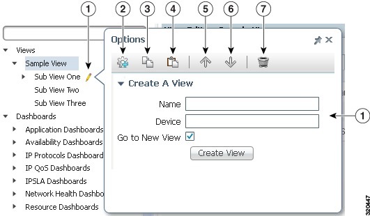
|
|
|
||
|
|
|
||
|
|
|
||
|
|
|
To modify the copied view, see Modifying Custom Report Views and Editing Views.
Modifying Custom Report Views
Your ability to modify custom views depends upon the permissions you were assigned. By default, System Administrator users can view and edit any custom view. If you are not a system administrator, you can modify custom views only when you are a Views Administrator and the view permissions allow you to edit the view.
To modify a custom report view:
Step 1![]() From the Performance menu, select Views.
From the Performance menu, select Views.
Step 2![]() In the navigation area, choose the custom report view or subview that you want to modify.
In the navigation area, choose the custom report view or subview that you want to modify.
Step 3![]() From the main View tab toolbar (Figure 7-8) perform any of the following changes to report views.
From the main View tab toolbar (Figure 7-8) perform any of the following changes to report views.
These actions affect all graphs contained in the view. Not all toolbar tools will be available, depending on the read and write permissions for the view.
- Home —Makes the view your home view. After you click it, “(Home View)” appears in the view title, and this view appears when you click the main menu Home icon. (See Figure 3-1.)
- Paste Graphs from Clipboard —Pastes report graphs copied from other reports.
- Columns —Changes the graph width, from 1 to 3 columns. 2 is the default.
- Graph Mode —Displays all view reports in graphs.
- Table Mode —Displays all view reports in tables.
Note![]() In table mode, an Export to CSV tool is added to the toolbar.
In table mode, an Export to CSV tool is added to the toolbar.
- Show/Hide Graph Legends —Displays or hide legends from the report graphs.
- Enable Compact Mode —Reduces the graph size and see more graphs within the same screen area. Enabling compact mode can be useful when trying to see patterns among multiple graphs.
- Merge Selected Graphs —Merges two or more selected graphs. See Merging Graphs in Views.
- Disable Automatic Updates —Prevents the report from being updated; click Enable Automatic Updates to allow updates. This function is provided when continual, automatic updates are not needed.
- Email Report —Emails the report. See Emailing Reports, for information about setting up schedules for emailing graphs as graphic files or PDFs to other users by email.
- Refresh —Manually updates all the graphs and tables in the page.
Note![]() Refresh will not refresh the page if the page is locked.
Refresh will not refresh the page if the page is locked.
- Play View —Scrolls through the views automatically. This option appears only when you display the highest level of your created view. You can change the view interval (20 seconds is the default) and display type (inline or full screen) in User Preferences. See Customizing the GUI and Information Display.
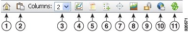
|
|
|
||
|
|
|
||
|
|
|
||
|
|
|
||
|
|
|
||
|
|
|
Step 4![]() From each report graph toolbar you can perform any of the following changes.
From each report graph toolbar you can perform any of the following changes.
Note![]() These actions affect only the individual graph. Not all toolbar tools will be available, depending on the read and write permissions for the views.
These actions affect only the individual graph. Not all toolbar tools will be available, depending on the read and write permissions for the views.
- Hide Row/Display Row —Hides or displays the view row.
- Drag to Reorder Items —Click and drag the graph to a new location within the view.
- Delete —Deletes the report item from the report.
- Graph Mode —Displays the report item in graph view.
- Table Mode —Displays the report item in table view.
- Comparative View —Displays a full-screen comparative view of the report, for example a 15-minute and hourly comparison.
- Edit —Displays the Edit Report Properties dialog box where you can modify the graph name, add or edit a subtitle, and modify the columns displayed in the graph summary table:
Use Default Columns—Enables the default columns listed below. If not selected, you can choose any of the following columns:
–![]() Std Dev (standard deviation; default)
Std Dev (standard deviation; default)
Additionally, under Customize Reference Line you can add or modify a graph reference line:
–![]() Name—The reference line name.
Name—The reference line name.
–![]() Value—The value where you want the reference line to appear. This should be within the range displayed on the chart X axis.
Value—The value where you want the reference line to appear. This should be within the range displayed on the chart X axis.
–![]() Color—Sets the reference line color.
Color—Sets the reference line color.
–![]() Opacity—Sets the reference line opacity. You can use the slider or enter a numeric value. The range is.05 to 1 (default).
Opacity—Sets the reference line opacity. You can use the slider or enter a numeric value. The range is.05 to 1 (default).
–![]() Display Data Series Lines in Red/Green for Values Above/Below Reference Line—If enabled, the reference line is hidden. Data series lines above the reference line value appear in red, and data series lines below the reference line value appear in green.
Display Data Series Lines in Red/Green for Values Above/Below Reference Line—If enabled, the reference line is hidden. Data series lines above the reference line value appear in red, and data series lines below the reference line value appear in green.
If you create multiple reference lines, you can only apply the red/green optionI to one of them. f you enable the red/green option and decide you do not want it enabled, delete the reference line and create a new one.
Click Save after you complete the view graph property edits.
- Copy to Clipboard —Copies the report to the Prime Performance Manager clipboard to allow you to paste it into other views.
- Email Report —Emails the graph to selected recipients.
- Select this Graph —Selects the graph. The function allows you to select multiple graphs and merge them into one graph using the Merge Selected Graphs tool.
Note![]() If Compact Mode is enabled, the graph toolbar is not displayed.
If Compact Mode is enabled, the graph toolbar is not displayed.
Inside each view graph, the following options are available:
These are the same options that are available for report graphs. See Customizing Report Display, for descriptions of these options.
Step 5![]() If devices are attached to the view, the following device menus are displayed:
If devices are attached to the view, the following device menus are displayed:
For descriptions of the device menus, see Displaying Device Information at the Device Level.
Editing Graphs in Custom Views
To edit graphs in your custom view:
Step 1![]() Display the view containing the graphs you want to edit.
Display the view containing the graphs you want to edit.
Step 2![]() On the graph toolbar, click Edit.
On the graph toolbar, click Edit.
Step 3![]() In the Edit Report Properties dialog box, enter the following:
In the Edit Report Properties dialog box, enter the following:
–![]() Std Dev (standard deviation; default)
Std Dev (standard deviation; default)
Step 4![]() Edit the graph reference line or add a chart reference line by clicking Add Reference Line:
Edit the graph reference line or add a chart reference line by clicking Add Reference Line:
Merging Graphs in Views
Merging graphs in views can be useful to create a composite view of similar data within similar times. For example, graphs for TE tunnels between two provider edge (PE) devices could be merged into one graph to give a composite view of traffic between the two PEs, for example:
ifInOctects TE_Tunnel_1000_PE_A__PE_B
ifOutOctects TE_Tunnel_1000_PE_A__PE_B
ifInOctects TE_Tunnel_1001_PE_B__PE_A
ifOutOctects TE_Tunnel_1001_PE_B__PE_A
Note![]() To maximize the effectiveness of merged graphs, merged graphs should have similar data and time frames.
To maximize the effectiveness of merged graphs, merged graphs should have similar data and time frames.
Note![]() Although you can merge any number of graphs at one time, you can only define two labeled axes.
Although you can merge any number of graphs at one time, you can only define two labeled axes.
Step 1![]() Display the view containing the graphs you want to merge.
Display the view containing the graphs you want to merge.
Step 2![]() Click Select This Graph (the bottom tool on the left side of the graph) for each graph you want to merge.
Click Select This Graph (the bottom tool on the left side of the graph) for each graph you want to merge.
Step 3![]() On the Views toolbar, click Merge Selected Graphs.
On the Views toolbar, click Merge Selected Graphs.
Step 4![]() In the Edit Merged Graph Properties dialog box, enter the following:
In the Edit Merged Graph Properties dialog box, enter the following:
Step 5![]() In the Edit Report Properties dialog box, enter the following:
In the Edit Report Properties dialog box, enter the following:
- Custom Report Name—Edit the report name.
- Custom Subtitle—(optional) Edit (or add) a subtitle.
- Primary Axis—Edit the text of the primary axis, if needed. The primary axis is the name of the first chart you selected.
- Secondary Axis—Edit the text of the secondary axis, if needed. The secondary axis is the name of the second chart you selected.
- Use Default Columns—If selected, the default columns are used in the chart. If not selected, you can choose one or more of the following columns:
–![]() Std Dev (standard deviation; default)
Std Dev (standard deviation; default)
Step 6![]() Edit the chart reference line or add a chart reference line by clicking Customize Reference Line:
Edit the chart reference line or add a chart reference line by clicking Customize Reference Line:
–![]() Name—The reference line name.
Name—The reference line name.
–![]() Value—The value where you want the reference line to appear. This should be within the range displayed on the chart X axis.
Value—The value where you want the reference line to appear. This should be within the range displayed on the chart X axis.
–![]() Color—Sets the reference line color.
Color—Sets the reference line color.
–![]() Opacity—Sets the reference line opacity.
Opacity—Sets the reference line opacity.
The merged report appears beneath the other graphs.
Step 8![]() If you want to export the merged graphs as a CSV table, click Export Table as CSV.
If you want to export the merged graphs as a CSV table, click Export Table as CSV.
An Opening [ merged file name ].csv dialog box allows you to open the CSV file in Excel or save it to a local drive,
Tip You can use the Toggle Multiple Axes option in the Change Graph Display graph menu to toggle among the axes in merged charts.
Editing Views
You can edit any view to which you have edit permission and which have the Editable attribute turned on.
To hide or display views, and perform other view management tasks:
Step 1![]() From the Performance menu, select Views.
From the Performance menu, select Views.
Step 2![]() In the navigation area, choose the custom report view or subview that you want to modify.
In the navigation area, choose the custom report view or subview that you want to modify.
Tip Alternatively, you can search for views from any View Editor tab by entering text strings. Views or subviews with text in their titles that match the search text titles will be displayed.
Step 3![]() Click the View Editor tab.
Click the View Editor tab.
Step 4![]() As needed, modify the following:
As needed, modify the following:
–![]() Private—Editable only by the view creator or System Administrator users.
Private—Editable only by the view creator or System Administrator users.
–![]() Public—Editable by any user.
Public—Editable by any user.
–![]() Group—If the user creating the view is a System Administrator, the view will be editable only by users who are members of the user group(s) selected under Groups. If the user creating the view is a Views Administrator, the view will be editable to whatever group the Views Administrator is currently in.
Group—If the user creating the view is a System Administrator, the view will be editable only by users who are members of the user group(s) selected under Groups. If the user creating the view is a Views Administrator, the view will be editable to whatever group the Views Administrator is currently in.
–![]() Private—Viewable only by creator or System Administrator users.
Private—Viewable only by creator or System Administrator users.
–![]() Group—If the user creating the view is a System Administrator, the view will be viewable only by users who are members of the user group(s) selected under Groups. If the user creating the view is a Views Administrator, the view will be viewable to whatever group the Views Administrator is currently in.
Group—If the user creating the view is a System Administrator, the view will be viewable only by users who are members of the user group(s) selected under Groups. If the user creating the view is a Views Administrator, the view will be viewable to whatever group the Views Administrator is currently in.
a.![]() From the View Editor toolbar, click Add Subview.
From the View Editor toolbar, click Add Subview.
b.![]() In the Add Subview dialog box, enter the subview name and, if you want to attach a device, the device hostname or IP address.
In the Add Subview dialog box, enter the subview name and, if you want to attach a device, the device hostname or IP address.
Step 6![]() To delete, edit, or display a view, from the View Editor Actions column, click the following:
To delete, edit, or display a view, from the View Editor Actions column, click the following:
Note![]() Alternatively, you can choose Edit View or Delete View from the view context menu, shown in Figure 7-7.
Alternatively, you can choose Edit View or Delete View from the view context menu, shown in Figure 7-7.
Step 7![]() To change the position of a view or subview, select the view then click the up or down arrow under the Move View column.
To change the position of a view or subview, select the view then click the up or down arrow under the Move View column.
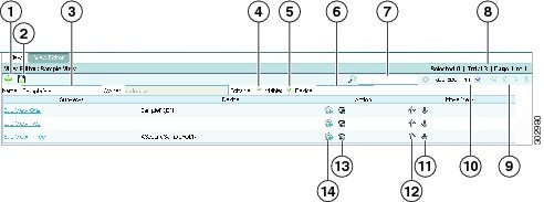
|
|
|
||
|
|
|
||
|
|
|
||
|
|
|
||
|
|
|
||
|
|
|
||
|
|
|
Managing Large Numbers of Views
Two user preferences (see Customizing the GUI and Information Display) help you manage large numbers of views:
These settings control the number of views displayed on a view tree. If the number of view tree items reaches the maximum, the top subview is rolled out and the new view item is added at the bottom. This allows you to scroll through many views while keeping your screen real estate manageable. Other view management elements include:
- Ellipsis—An ellipsis after a view indicates the number of subviews on the view tree has reached the default setting.
- Pencil icon—Depending on the user permissions, a pencil icon provides quick access to view operations including edit, copy, paste, move, delete, and create.
- View browse history—Prime Performance Manager retains a history of the views that you visit in a given session. You can go back and forth among views and view levels as you would with website pages.
To clean up views and return to the default order, that is, the top 10, you can:
- Restart the gateway. The view history for all users would be reset.
- Close a view to reset it for the current user
Working with Data Center Views
Prime Performance Manager delivers many Data Center views. When working with these views, keep the following in mind:
- If the Data Center feature is disabled, the views won't appear.
- Data center views can automatically build relationships between physical devices and logical devices such as UCS and ESXi, UCS and vCenter, and VSS and VDC devices.
- Data Center views cannot be edited, so some operation buttons are not available. However, you can copy Data Center views, then edit the copied views.
Creating and Managing Report Groups
Prime Performance Manager allows you to generate reports based on groups of network objects, for example, devices, interfaces, CPUs, or a combination of devices and device elements. You create the group by providing a list of network objects that you want included, or by providing an algorithm that is used to search the network and return objects that meet the provided criteria.
Creating new groups might require you to create new group reports. Information for creating group reports is provided in the Cisco Prime Performance Manager 1.7 Integration Developer Guide. Prime Performance Manager includes example groups in four categories: Mobile IOS Statistics, Mobile StarOS Statistics, Transport Statistics, and Video Broadcast.
Group elements that you work with in the Prime Performance Manager GUI include:
- Group ID—Is assigned by Prime Performance Manager when a group is created. It uniquely identifies the group.
- Editable (true or false)—Indicates whether the group can be edited by other users. If true, users with the appropriate permissions can edit the group. If the XML for a group is in the groups/system/ directory, it is not editable by any user from the GUI, If it is in the groups/user/ directory, it is editable by anyone with access to the group editor.
- Enabled (true or false)—Enables or disables the group. If true, the group processes the input data and returns the appropriate return values. If false, the group does not return any data.
- Name—Is assigned by the group creator. This is the group name displayed in the GUI.
- Algorithm—Defines the criteria Prime Performance Manager uses to search the network for objects. The algorithm is built from macros joined by standard operators, for example, +, =, >=, and others. The algorithm final output is true (the object meets the criteria and is included) or false (the object does not meet the criteria and is not included). For example, the following algorithm return devices with “To_Rome” or “To_Venice” in the interface descriptions:
- Objects—Is a list of objects by their Fully Qualified Domain Names (FQDNs) that map to objects within the Prime Performance Manager network. The object format is:
Node=<host or IP>,<other keys as defined in the corresponding report XML file>
The objects contained in this list are included in the group processing. Objects are returned if they meet the criteria specified in the algorithm or items in the Objects list.
- Type—Is used to identify the report domain to users. For example, a group that filters data at the network level may specify a Network type, while a group that filters data for a particular region may specify a Regional type. Specifying the domain is useful when reviewing grouped report information.
The following topics describe how to create, manage, and display group reports:
Provided Groups
Prime Performance Manager includes sample groups that are shipped in the disabled state. You can use these as standalone groups to generate network-level statistics or you can copy them and add algorithms to aggregate similar objects at different levels. For example, you might want to aggregate statistics to the network level as well as regional, group, or device levels.
- apn.xml—Aggregates the statistics for an APN (AccessPointName) to a network level on GGSN devices. An APN can be defined on multiple routers. This group aggregates APN statistics for all routers. It is defined into a single statistic. This aggregation type reports, for example, the sum of the up stream traffic volume for the APN in the network. It requires the device to implement the MIB, CISCO-GPRS-ACC-PT-MIB.my.
- pdngwApn.xml—Aggregates the statistics for an APN to the network level on PDNGW devices. An APN can be defined on multiple routers. This group aggregates the APN statistics for all routers. It is defined into a single statistic. This type of aggregation reports, for example, the sum of active PDPs for the APN in the network. It requires the device to implement the MIB, CISCO-GPRS-ACC-PT-MIB.my.
- sgwApn.xml—Aggregates the statistics for an APN to a network level on SGW devices. An APN can be defined on multiple routers and this group will aggregate the statistics for an APN for all routers. It is defined into a single statistic. This type of aggregation reports, for example, the sum of active PDP's for the APN in the network. It requires the device to implement the MIB, CISCO-GPRS-ACC-PT-MIB.my.
- spgwApn.xml—Aggregates the statistics for an APN to a network level on SPGW devices. An APN can be defined on multiple routers and this group will aggregate the statistics for an APN for all routers. It is defined into a single statistic. This type of aggregation reports, for example, the sum of active PDP's for the APN in the network. It requires the device to implement the MIB, CISCO-GPRS-ACC-PT-MIB.my.
- cableDownModem.xml—Aggregates the number of online downstream cable modems in the network.
- cableModem.xml—Summarizes the per-state count of all cable modems in network.
- cableUpModem.xml—Aggregates the number of online upstream cable modem in the network.
- dbdsApplicationProcessState.xml—Aggregates the application processes by state for Scientific America controllers.
- dbdsControllerProcess.xml—Aggregates the general purpose processes by state for Scientific America controllers.
The following groups aggregate data for the StarOS running on Cisco ASR 5000 platforms. The aggregated statistics are similar to those collected through the apn, pdngwApn, sgwApn, and spgwApn groups listed above.
Creating a Report Group
To display grouped reports within the Prime Performance Manager GUI:
Step 1![]() Log into the Prime Performance Manager GUI as the system administrator user.
Log into the Prime Performance Manager GUI as the system administrator user.
Step 2![]() From the Administration menu, choose Group Editor.
From the Administration menu, choose Group Editor.
Step 3![]() In the navigation area, click Groups Summary.
In the navigation area, click Groups Summary.
The default system groups are displayed:
Step 4![]() In the System Groups window, click the Create New Group tool.
In the System Groups window, click the Create New Group tool.
Step 5![]() In the Create Group dialog box, enter the group name. Valid characters are letters, numbers, underscores, hyphens, and periods. Spaces are not permitted. The group name must be unique.
In the Create Group dialog box, enter the group name. Valid characters are letters, numbers, underscores, hyphens, and periods. Spaces are not permitted. The group name must be unique.
The Group Details window is displayed.
Step 7![]() In the Group Details window, enter the parameters for the new group:
In the Group Details window, enter the parameters for the new group:
- Enabled—Check if you want the group enabled, that is, group report data will be collected and displayed.
- Section Name—Allows you to create multiple processing sets for the same group. For example, you might want to create a group of objects defined by multiple algorithms or objects lists. Each processing set is identified with a unique name. The default processing set is “default.” It cannot be deleted.
To create a new processing set, click +, then enter the new processing set name in the dialog that appears and click OK. Conversely, to delete a processing set, click -.
- Type/Tag—Enter the group type. The group type is a tag for the group processing section. It is used by other Prime Performance Manager functions to qualify the data. For example, in an aggregate report that uses this processing group the data is tagged with the type entered here. The type is included in each data row.
Note![]() You might see groups with a ppm_tenant type/tag. This tag is generated during the Prime Performance Manager OpenStack integration, which imports tenant information from OpenStack and creates ppm_tenant groups. When Prime Performance Manager processes report data, it checks the appropriate group definitions by summary processor and applies tags to the tenant data as defined by the algorithm and object list defined in the group. The summary processor specifies what report data is to be tagged and the group name specifies the data tag name. Do not specify the ppm_tenant tag through the GUI unless you are directed to by Cisco support.
You might see groups with a ppm_tenant type/tag. This tag is generated during the Prime Performance Manager OpenStack integration, which imports tenant information from OpenStack and creates ppm_tenant groups. When Prime Performance Manager processes report data, it checks the appropriate group definitions by summary processor and applies tags to the tenant data as defined by the algorithm and object list defined in the group. The summary processor specifies what report data is to be tagged and the group name specifies the data tag name. Do not specify the ppm_tenant tag through the GUI unless you are directed to by Cisco support.
- Data Source—Click Change and choose the data source you want included in the group by selecting the data source under Available Usages and clicking Add to move it to the Assigned Usages group. The data source identifies the report processors that use this group processing section when the group is enabled. Report processors are defined in the individual report XML files.
Note![]() A data source is not required. If you only want to create and use the group to filter on a report, you do not need to specify a data source, and the group does not need to be enabled. However, to do aggregation, the group must have a data source, or no results will appear when the group is enabled.
A data source is not required. If you only want to create and use the group to filter on a report, you do not need to specify a data source, and the group does not need to be enabled. However, to do aggregation, the group must have a data source, or no results will appear when the group is enabled.
Step 8![]() Enter the object selection criteria using one or both of the following:
Enter the object selection criteria using one or both of the following:
- Algorithm—Enter the algorithm that you want to use to define the objects added to the group. You can enter the algorithm by typing it into the Matching Algorithm box, or click Launch Algorithm Editor to create the algorithm using an editor. For information about using the algorithm editor, see Managing Report Groups. If you enter the algorithm directly, click Validate Algorithm to validate it.
- List of Objects—Enter a list of objects using the object FQDNs, using the format:
Node=<host or IP>,<other keys as defined in the corresponding report XML file>
To validate the algorithm, click Validate.
The new group is added to the Prime Performance Manager grouped reports list.
Managing Report Groups
After you create report groups, you can edit, enable, disable, duplicate, and delete them at any later time.
To edit, enable, disable, duplicate, or delete a grouped report:
Step 1![]() Log into the Prime Performance Manager GUI as the system administrator user.
Log into the Prime Performance Manager GUI as the system administrator user.
Step 2![]() From the Administration menu, choose Group Editor.
From the Administration menu, choose Group Editor.
Step 3![]() In the navigation area, click Groups Summary.
In the navigation area, click Groups Summary.
Step 4![]() To edit a group, click the group link under the Name column.
To edit a group, click the group link under the Name column.
Step 5![]() In the Group Details tab, edit any of the following:
In the Group Details tab, edit any of the following:
–![]() Edit the algorithm directly in the Matching Algorithm text box, then click Validate Algorithm to validate your edits, or,
Edit the algorithm directly in the Matching Algorithm text box, then click Validate Algorithm to validate your edits, or,
–![]() Click Launch Algorithm Editor and edit the algorithm in the algorithm editor.
Click Launch Algorithm Editor and edit the algorithm in the algorithm editor.
For field descriptions and entry examples, see Creating a Report Group.
Step 6![]() To enable, disable, duplicate, or delete groups:
To enable, disable, duplicate, or delete groups:
b.![]() Highlight the groups you want to enable, disable, or delete. Press Shift to choose more than one group.
Highlight the groups you want to enable, disable, or delete. Press Shift to choose more than one group.
c.![]() From the Actions menu, choose the action you want to perform:
From the Actions menu, choose the action you want to perform:
d.![]() On the confirmation, click OK.
On the confirmation, click OK.
Displaying Group Reports
Group reports are displayed following steps similar to the display of non-group reports. To display a group report:
Step 1![]() Log into the Prime Performance Manager GUI.
Log into the Prime Performance Manager GUI.
Step 2![]() From the Performance menu, choose Reports.
From the Performance menu, choose Reports.
Step 3![]() Click Grouped Reports, then navigate to the report you want to see.
Click Grouped Reports, then navigate to the report you want to see.
The group report appears on the content area. For information on managing the report display, see Customizing Report Display.
Creating Web Reports
Prime Performance Manager allows you to define a new report by using report metrics that are already in place for existing reports. This feature allows you to choose report metrics that are defined in current report ProcessDBSummary tables, but not from the report Poll sections. Fundamentally, you can create WebReport sections using the following report elements:
- Name—Ensures the report is kept unique.
- Category—Where the report appears in the report tree.
- Context—The report index structure.
- Filtering
- GraphView and graphsPerRow
–![]() GraphSummary + title + hide/show options
GraphSummary + title + hide/show options
–![]() Graph + title—Util/Column/Bytes columns
Graph + title—Util/Column/Bytes columns
–![]() LeafGraph + title—Util/Column/Bytes columns
LeafGraph + title—Util/Column/Bytes columns
Step 1![]() Log into the Prime Performance Manager GUI as an administrator user.
Log into the Prime Performance Manager GUI as an administrator user.
Step 2![]() From the Network menu, choose Web Report Editor.
From the Network menu, choose Web Report Editor.
Step 3![]() On the Get Started With The Web Report Editor screen, choose Create New Web Report Document and click Go.
On the Get Started With The Web Report Editor screen, choose Create New Web Report Document and click Go.
Note![]() You can also use the Web Report Editor to open existing web reports. If the web report is a user report located in the user directory, you can edit it directly. If it is a system report located in the system directory, the Web Report Editor will save a copy in the user directory and and use this report as long as it exists.
You can also use the Web Report Editor to open existing web reports. If the web report is a user report located in the user directory, you can edit it directly. If it is a system report located in the system directory, the Web Report Editor will save a copy in the user directory and and use this report as long as it exists.
Step 4![]() On the Basic Report Properties screen, enter the report basic properties:
On the Basic Report Properties screen, enter the report basic properties:
–![]() To filter the data sources, enter the first several letters of the data source, for example, entering MPLS displays MPLS data sources.
To filter the data sources, enter the first several letters of the data source, for example, entering MPLS displays MPLS data sources.
–![]() As you scroll over the available data sources, the data source variables appear on the right. The data source keys are identified with a key icon.
As you scroll over the available data sources, the data source variables appear on the right. The data source keys are identified with a key icon.
After you choose the data source the Report Preview is automatically updated with the report XML for the chosen data source.
- File Name—Enter a name for the report file. Only alphanumeric characters are permitted. Special characters, including spaces, are not allowed.
- Readable Name—Is automatically populated with the file name. Enter another name, if needed.
- Report Tree Location—Sets the location of the report in the Reports navigation tree:
–![]() Use Existing—Displays existing navigation tree top categories sequentially and allows you to place the report in an existing category.
Use Existing—Displays existing navigation tree top categories sequentially and allows you to place the report in an existing category.
–![]() Create New—Allows you to create a new navigation tree category and sublevels.
Create New—Allows you to create a new navigation tree category and sublevels.
- Text Properties File Name—Is automatically populated with the [ file name ].properties. The field is not editable.
- Criteria—Click the field and choose the report criteria from the displayed list of network device capabilities.
- Go Live Disabled—Check if you do not want Go Live enabled for this report. The Go Live option allows users to initiate 15-second polling for device-level reports.
- Show Compact—Check if you want the report displayed in compact mode. In compact mode, when graph output is selected the Zoom, Aggregate Lines, Graph Styles, and Export Graphs tools displayed inside graphs are hidden. Additionally, the graph border is hidden and graph title reduced in size. This option reduces the overall size of the graph and is useful when screen real estate is needed.
Step 6![]() Enter the graph view properties:
Enter the graph view properties:
- Summary Table Title Tag—Enter the title of the report summary table.
- Readable Summary Table Title—Enter the summary table title displayed to users. You can enter alphanumeric characters. No special characters are allowed including spaces.
- Summary Table Minimized—Check this box if you want the summary table minimized when the report is first displayed.
- Show Legend by Default—Check this box if you want the graph legends displayed by default.
- Enable Leaf Graph—Check if you want to enable leaf graphs in the report. If checked, the following leaf graph fields appear:
–![]() Leaf Graph Readable Title—A readable leaf graph title.
Leaf Graph Readable Title—A readable leaf graph title.
–![]() Leaf Graph Title—The actual leaf graph title.
Leaf Graph Title—The actual leaf graph title.
–![]() Default Graph Type—Allows you to choose the default graph type. Line is the default. Other choices include Bar, Stacked Column, Stacked Percentage Column, Utilization Area, and Utilization Column. For descriptions, see Customizing Report Display.
Default Graph Type—Allows you to choose the default graph type. Line is the default. Other choices include Bar, Stacked Column, Stacked Percentage Column, Utilization Area, and Utilization Column. For descriptions, see Customizing Report Display.
Note![]() A leaf graph is a combined graph that appears when you drill down to the appropriate level. For example, if a report has graphs A, B, and C, and Enable Leaf Graph is checked, A, B, and C will display the top 10 series at the network level. However, if you click a device and drill to a lower level, a fourth graph is displayed that combines the A, B, and C series on one graph. Leaf graphs only appear when you drill to a sufficient level, depending on context.
A leaf graph is a combined graph that appears when you drill down to the appropriate level. For example, if a report has graphs A, B, and C, and Enable Leaf Graph is checked, A, B, and C will display the top 10 series at the network level. However, if you click a device and drill to a lower level, a fourth graph is displayed that combines the A, B, and C series on one graph. Leaf graphs only appear when you drill to a sufficient level, depending on context.
Step 8![]() In the Graph Properties window, complete the following graph fields:
In the Graph Properties window, complete the following graph fields:
After you enter the graph title, the Readable Graph Title, Column Name Tag, and Readable Column Name are automatically populated with the graph title.
–![]() Avg—Average value (checked by default).
Avg—Average value (checked by default).
–![]() Max—Maximum value (checked by default).
Max—Maximum value (checked by default).
- Column Name Tag—The name of the column.
- Readable Column Name—The readable column name.
- Variable—The variable associated with the graph. All variables associated with the data source are available except for key columns and the TenantId column. If you choose Custom Formula, a Custom Formula/KPI field appears where you can enter a custom formula.
- Show as Rate—Causes the data to be displayed as a rate. For example, if your variable is InPkts, checking the box will create the XML, InPkts / IntervalDuration(), which will cause the data to display as a rate.
- Variable Type—Sets the variable type:
If you choose ipAddr, a checkbox appears allowing you to indicate whether it is a key.
- Default Value—The default value.
- No Data Value—The value displayed when no data is present.
- Decimal Precision—The decimal precision, entered as zeros.
- Sortable—If checked (default), indicates the graph is sortable.
- Descending—If checked (default), indicates the data is displayed in descending values.
- Thresholdable—If checked (default), indicates thresholds can be provisioned on the data.
- Filterable—If checked (default), indicates the graph is filterable.
- Default Sort Column—If checked, indicates the column is the default sort column
- TCA Rising—If checked (default), indicates the threshold crossing alert, if provisioned, is rising. (This value is ignored if Thresholdable is not enabled.)
- No Color—Indicates no colors are displayed on the graph.
- Down Colors—Indicates down colors are displayed on the graph.
- Show Percentage Column—Adds a column in the graph view summary table that shows the value as a percent. For example, if the column is InPkts and you check this box, the summary table will have an Avg column but will also have a Avg as % column. If the average value is 10, and that represents 14.3% of the top ten (all the rows in the summary table), 14.3 will appear in the Avg as % column.
- Hide Series—Hides this series in the leaf graph by default. If a user views the leaf graph, it is as if they clicked on the series in the legend to hide it. They can still select it in the legend to display the series. If a report has graphs A-D, and A and B have Hide Series checked, the leaf graph will only show series C and D. A and B will be grayed out in the legend.
The graph is added to the report. The Graph View Properties window displays the key properties.
Step 10![]() If you want to add another graph to the report, click Add under Graph View on the left and repeat Steps 6 through 9 . If not, click Next.
If you want to add another graph to the report, click Add under Graph View on the left and repeat Steps 6 through 9 . If not, click Next.
Step 11![]() If you want to a add filter, under Filters click Add, then enter the following filter properties:
If you want to a add filter, under Filters click Add, then enter the following filter properties:
Step 13![]() If you want to add another graph to the report, click Add under Graph View on the left and repeat Steps 6 through 12 . If not, click Next.
If you want to add another graph to the report, click Add under Graph View on the left and repeat Steps 6 through 12 . If not, click Next.
Step 14![]() On the Final Preview window, preview the web report XML under Report Preview. If needed, you can make manual adjustments by editing the report XML.
On the Final Preview window, preview the web report XML under Report Preview. If needed, you can make manual adjustments by editing the report XML.
Step 16![]() On the Confirmation dialog, click OK.
On the Confirmation dialog, click OK.
The new report is added to Prime Performance Manager.
Deleting Web Reports
To delete a user-created web report:
Step 1![]() Log into the Prime Performance Manager GUI as an administrator user.
Log into the Prime Performance Manager GUI as an administrator user.
Step 2![]() From the Network menu, choose Web Report Editor.
From the Network menu, choose Web Report Editor.
Step 3![]() On the Get Started With The Web Report Editor screen, choose View/Edit/Delete Existing Web Report Document, then click Go.
On the Get Started With The Web Report Editor screen, choose View/Edit/Delete Existing Web Report Document, then click Go.
Step 4![]() In the Search Web Reports dialog box, enter the title of the web report you want to delete, or scroll to the report in the web report list.
In the Search Web Reports dialog box, enter the title of the web report you want to delete, or scroll to the report in the web report list.
Step 5![]() Click Delete Web Report.
Click Delete Web Report.
Note![]() If the Delete Web Report is not active, the report is a system report and cannot be deleted. You can only delete user reports.
If the Delete Web Report is not active, the report is a system report and cannot be deleted. You can only delete user reports.
Step 6![]() On the confirmation, click OK.
On the confirmation, click OK.
 Feedback