- About This Book
- Using the Prime Fulfillment Graphical User Interface
- Setting Up Prime Fulfillment Services
- Managing Carrier Ethernet and L2VPN Services
- Managing RAN Backhaul Services
- Managing MPLS VPN Services
- Managing MPLS Transport Profile Services
- Managing MPLS Traffic Engineering Services
- Managing Service Requests
- Managing Templates and Data Files
- Monitoring
- Performing Diagnostics
- Using the Topology Tool
- Using Inventory Manager
- Administration Tasks
- Cisco Configuration Engine Server
- Property Settings
- WatchDog Commands
- XML Reference
- Terminating an Access Ring on Two N-PEs
- Repository Views
- Inventory - Discovery
- Adding Additional Information to Services
Cisco Prime Fulfillment User Guide 6.2
Bias-Free Language
The documentation set for this product strives to use bias-free language. For the purposes of this documentation set, bias-free is defined as language that does not imply discrimination based on age, disability, gender, racial identity, ethnic identity, sexual orientation, socioeconomic status, and intersectionality. Exceptions may be present in the documentation due to language that is hardcoded in the user interfaces of the product software, language used based on RFP documentation, or language that is used by a referenced third-party product. Learn more about how Cisco is using Inclusive Language.
- Updated:
- March 20, 2015
Chapter: Managing MPLS Transport Profile Services
Managing MPLS Transport Profile Services
This chapter describes the tasks required to get started using Cisco Prime Fulfillment 6.2, Multiprotocol Label Switching (MPLS) Transport Profile (TP) services.
This section covers the following topics:
•![]() Prerequisites and Limitations
Prerequisites and Limitations
•![]() Creating an MPLS-TP Service Request
Creating an MPLS-TP Service Request
Introduction
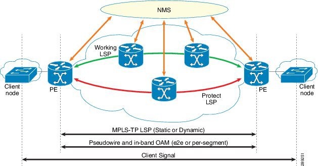
MPLS-TP is a transport service (managed by Prime Fulfillment) for a dynamic MPLS core (not managed by Prime Fulfillment).
In the current implementation of MPLS-TP, an MPLS-TP tunnel can be provisioned between two arbitrary nodes in an MPLS-TP enabled network. The provisioned tunnel can have one or two paths, a working and an optional protect label-switched path (LSP). The normal use case is for Prime Fulfillment to automatically calculate the working and protect paths using a path selection algorithm that chooses MPLS-TP enabled links based on shortest path, and to provision the tunnel on the endpoints and all nodes traversed by the tunnel.
Figure 6-1 An MPLS-TP Enabled Network
Prerequisites and Limitations
The current release of Prime Fulfillment involves certain prerequisites and limitations, which are described in the Cisco Prime Fulfillment Installation Guide 6.2, including general system recommendations.
Note that Internet Explorer 8 (IE8) will not show the calculated path graphically (as described in Creating an MPLS-TP Service Request) as IE8 offers no support for SVG display. Until IE9 is supported, a textual summary of the path can be used to review the path in IE8.
For supported device and OS information , refer to Cisco Prime Fulfillment Supported Devices 6.2.
Preconfiguration Process
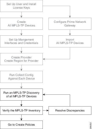
The preconfiguration process sets up key parameters that enable the system to collect MPLS-TP network information and subsequently deploy MPLS-TP configurations on the chosen network.
The different steps in the preconfiguration process are provided in Figure 6-2.
Figure 6-2 Preconfiguration Process
Before commencing the preconfiguration process, MPLS-TP needs to be enabled on the network devices by making sure that the IP addresses used as devices' MPLS-TP IDs are accessible from the management station (this step is not supported by MPLS-TP). This is described in Other MPLS-TP Preconfiguration Requirements.
Setting up new user and installing license keys is described in Chapter 14 "Administration Tasks" and the other steps are covered in Setting Up Devices and Device Groups and the Inventory - Discovery appendix (Collect Config step).
See below for a description of specific MPLS-TP user roles.
The MPLS-TP-specific steps are as follows:
1. ![]() Run an MPLS-TP Discovery Task—Use Task Manager to discover the MPLS-TP network for a particular MPLS-TP provider to populate the repository with a view to creating primary and backup tunnels. (See Running MPLS-TP Discovery.)
Run an MPLS-TP Discovery Task—Use Task Manager to discover the MPLS-TP network for a particular MPLS-TP provider to populate the repository with a view to creating primary and backup tunnels. (See Running MPLS-TP Discovery.)
2. ![]() Verify the MPLS-TP Inventory—Verify that the MPLS-TP Discovery task was successfully completed. This can be done in a couple of ways. (See Verifying the MPLS-TP Discovery Results.)
Verify the MPLS-TP Inventory—Verify that the MPLS-TP Discovery task was successfully completed. This can be done in a couple of ways. (See Verifying the MPLS-TP Discovery Results.)
MPLS-TP Setup and Installation
Before setting up Prime Fulfillment, the Prime Fulfillment software must be installed. To do so, see the Cisco Prime Fulfillment Installation Guide 6.2.
To set up a new Prime Fulfillment user, one or more users with a MPLS-TP role must be created. MPLS-TP roles are decribed in MPLS-TP User Roles and step by step instructions for creating user roles are documented in Users.
Licensing information, including the Prime Fulfillment licensing options and the procedure needed to install licenses is described in Licensing.
MPLS-TP User Roles
Prime Fulfillment currently supports two MPLS-TP roles, the MPLS-TPRole and MPLS-TPServiceOpRole. These 2 user roles behave similarly to the other roles in Prime Fulfillment, for example the MPLSRole and the MPLSServiceOpRole found in MPLS.
They have the following permissions:
–![]() MPLS-TPRole—full permission to manage the inventory (create, read, update, delete, and deploy MPLS-TP policies and service requests)
MPLS-TPRole—full permission to manage the inventory (create, read, update, delete, and deploy MPLS-TP policies and service requests)
–![]() MPLS-TPServiceOpRole—permission to deploy MPLS-TP service requests
MPLS-TPServiceOpRole—permission to deploy MPLS-TP service requests
For an explanation of how to work with roles, see User Roles.
Other MPLS-TP Preconfiguration Requirements
Prior to performing MPLS-TP provisioning, perform the following additional configuration steps:
Step 1 ![]() Enable MPLS-TP on the device:
Enable MPLS-TP on the device:
•![]() Choose a global ID common to all devices (AS number, for example)
Choose a global ID common to all devices (AS number, for example)
•![]() Allocate a device ID to each device.
Allocate a device ID to each device.
•![]() Configure MPLS-TP-related timers.
Configure MPLS-TP-related timers.
Step 2 ![]() Configure a range of statically defined MPLS labels to be used by MPLS-TP tunnels and static pseudowires.
Configure a range of statically defined MPLS labels to be used by MPLS-TP tunnels and static pseudowires.
Step 3 ![]() Enable MPLS-TP links to select which interfaces will form the links in the MPLS-TP topology:
Enable MPLS-TP links to select which interfaces will form the links in the MPLS-TP topology:
•![]() Give each interface an ID.
Give each interface an ID.
•![]() Optionally configure a bandwidth pool on each interface.
Optionally configure a bandwidth pool on each interface.
•![]() Enable CDP on the MPLS-TP enabled links. This is not needed for MPLS-TP but is required for MPLS-TP discovery to work in Prime Fulfillment.
Enable CDP on the MPLS-TP enabled links. This is not needed for MPLS-TP but is required for MPLS-TP discovery to work in Prime Fulfillment.
Step 4 ![]() Create a BFD class to be used to monitor your MPLS-TP tunnels.
Create a BFD class to be used to monitor your MPLS-TP tunnels.
Running MPLS-TP Discovery
As a prerequisite for running MPLS-TP discovery, all devices must be present and a Collect Config task must be run (see the Inventory - Discovery appendix, Collect Config step).
The MPLS-TP network is discovered using the MPLS-TP Discovery task. This populates the repository with the network topology in an automated way. The necessary steps are described in this section.

Note ![]() MPLS-TP discovery will update only the functional MPLS-TP links in the MPLS-TP routing diagram (Service Request Editor, Review Routing accordion).
MPLS-TP discovery will update only the functional MPLS-TP links in the MPLS-TP routing diagram (Service Request Editor, Review Routing accordion).
The MPLS-TP discovery process discovers the following from the live network:
•![]() TP enabled links
TP enabled links
•![]() MPLS Static label pools
MPLS Static label pools
•![]() MPLS Static label pool usage
MPLS Static label pool usage
•![]() BFD templates
BFD templates
•![]() TP Router ID
TP Router ID
•![]() TP Global ID
TP Global ID
Where possible, the discovery process will try to keep the repository consistent with the network, for example delete links which have been removed. In cases where this is not possible, for example if a link is in use, a log message will be recorded.
This section includes the following:
•![]() Creating an MPLS-TP Discovery Task
Creating an MPLS-TP Discovery Task
•![]() Creating an MPLS-TP Discovery Task
Creating an MPLS-TP Discovery Task
•![]() Verifying the MPLS-TP Discovery Results
Verifying the MPLS-TP Discovery Results
Creating an MPLS-TP Discovery Task
To create a MPLS-TP Discovery task on the MPLS-TP network, use the following steps:
Step 1 ![]() Choose Operate > Task Manager.
Choose Operate > Task Manager.
The Task Manager window appears.
Step 2 ![]() Create a new task by selecting Create > MPLS-TP Discovery.
Create a new task by selecting Create > MPLS-TP Discovery.
The Create Task window appears.
Step 3 ![]() Make any desired changes to the auto-generated name and description text and click Next.
Make any desired changes to the auto-generated name and description text and click Next.
The MPLS-TP Discovery window appears.
Step 4 ![]() Select the devices through which the MPLS-TP network should be discovered.
Select the devices through which the MPLS-TP network should be discovered.
Step 5 ![]() Click Submit.
Click Submit.
The discovery process begins.
Step 6 ![]() Once the MPLS-TP discovery task is complete, the outcome will be documented in a log under
Once the MPLS-TP discovery task is complete, the outcome will be documented in a log under
Operate > Task Logs.
Links and resource pools should now be visible in the MPLS-TP Details window, which is accessible from the Inventory > Devices > MPLS-TP Details page.
Verifying the MPLS-TP Discovery Results
After running MPLS-TP Discovery, you can see the result in various ways.
Viewing Logs
Once the MPLS-TP Discovery task is completed, you can view the log that is generated. This summary log will list any changes that have occured in the MPLS-TP network.
To view the log, select the relevant task in Task Manager and click Logs.
Verifying Links, Pools, and MPLS-TP Global and Router IDs
To verify the status of links and pools, go to the MPLS-TP Details page at Inventory > Devices > MPLS-TP Details.
The MPLS-TP global and router IDs for a particular device can be verified by going to Inventory > Devices > Edit.
Creating an MPLS-TP Policy
An MPLS-TP policy is needed to successfully create and deploy a service request. It serves as a template for the settings that are needed on the device.
To create an MPLS-TP policy, use the following steps:
Step 1 ![]() Choose one of the following:
Choose one of the following:
a. ![]() Service Design > Policy Manager.
Service Design > Policy Manager.
In the Policy Manager window, click Create.
b. ![]() Service Design > Create Policy.
Service Design > Create Policy.
In either case, a Policy Type drop-down appears.
Step 2 ![]() Click the down-arrow to open the Policy Types drop-down list and select MPLS-TP Tunnel.
Click the down-arrow to open the Policy Types drop-down list and select MPLS-TP Tunnel.
The Policy Information accordion opens.
Step 3 ![]() Complete accordion 1 - Policy Information.
Complete accordion 1 - Policy Information.
Enter Policy Name and optionally a Description. Policy Name is the only field that is mandatory in the Policy Editor.
Step 4 ![]() Click Next.
Click Next.
The Policy Information accordion closes and the next accordion opens.
Step 5 ![]() Complete accordion 2 - Tunnel Characteristics.
Complete accordion 2 - Tunnel Characteristics.
Set how each of the attributes will be displayed within the Service Request Editor window using the drop-down next to each field:
•![]() Editable will display the attribute and permit modification.
Editable will display the attribute and permit modification.
•![]() Visible will display the attribute but prevent editing.
Visible will display the attribute but prevent editing.
•![]() Hidden will not display the attribute.
Hidden will not display the attribute.
Make sure to select Editable for any fields that you want to be able to edit in the Service Request Editor.
Use the State field to indicate whether the tunnel should be provisioned with the shutdown command or not.
For path protection, keep the Protection box selected to have Prime Fulfillment autogenerate an alternate protective path for the new tunnel.
For the Diversity Options drop-down menu, choose one of the following options:
•![]() Node Diversity Required—Path calculation will fail if protection with unique nodes cannot be found.
Node Diversity Required—Path calculation will fail if protection with unique nodes cannot be found.
•![]() Node Diversity Desired—Allow a path with common nodes to be returned.
Node Diversity Desired—Allow a path with common nodes to be returned.
•![]() Link Diversity Only—Do not allow working and protection path to pass through the same links.
Link Diversity Only—Do not allow working and protection path to pass through the same links.
Step 6 ![]() Complete accordion 3 - Tunnel End-points.
Complete accordion 3 - Tunnel End-points.
As in the previous accordion, remember to specify which fields should be Editable, Visible, and Hidden in the Service Request Editor.
Complete the fields as needed, using the drop-downs to select source and destination nodes and BFD templates.
Select the required BFD templates from a list of available BFD templates on the source and destination devices respectively. A valid BFD template name is max. 31 characters long.
For an explanation of global ID and router ID, see Global ID and Router ID.
Step 7 ![]() Click Finish to create the policy.
Click Finish to create the policy.
The new policy appears in the list of tunnels in the Policy Manager.
Global ID and Router ID
Global ID and router ID are used to identify devices within the MPLS-TP network so they can be discovered and managed.
If you as a user decide to specify the router ID and global ID, those values will be used for tunnel creation. If they are not specified, the router ID and global ID configured on the device itself are used.
Every MPLS-TP tunnel and LSP has a unique ID formed by the concatenation of the Global ID, Router ID, Tunnel ID, and LSP ID of both ends of the tunnel. This ID is configured at every endpoint and midpoint of the tunnel. The Global ID and router ID are normally configured globally on a router but it is possible to override these values for specific tunnels. Prime Fulfillment is aware of the globally configured IDs and uses them when configuring tunnels but also allows you to override these values as needed.
Global ID
Every MPLS-TP enabled node can have an MPLS-TP global ID configured within the global configuration. If the Global ID is set at the MPLE-TP global configuration level, it will be used as the default global ID for all endpoint and midpoint configuration. If not configured, a global ID of 0 is used for configured tunnels unless a different value is explicitly specified within the tunnel configuration itself.
The MPLS-TP global ID is retrieved from a device via MPLS-TP discovery.
Router ID
To be MPLS-TP emabled, a device must have a router ID.
If neither the MPLS-TP router ID nor the MPLS-TP global ID can be retrieved from the device, this is logged in the corresponding MPLS-TP Discovery task log file and all remaining MPLS-TP Discovery steps are halted for this device. The device in question is flagged as being MPLS-TP Disabled.
Creating an MPLS-TP Service Request
An MPLS-TP service request needs to be created to deploy a service request. It is assumed that at least one MPLS-TP policy is available. If not, see Creating an MPLS-TP Policy.
To create an MPLS-TP service request, use the following steps:
Step 1 ![]() This operation can be done in two ways:
This operation can be done in two ways:
a. ![]() From the Policy Manager, select the desired policy and click Create Service Request.
From the Policy Manager, select the desired policy and click Create Service Request.
b. ![]() Choose Operate > Create Service Request.
Choose Operate > Create Service Request.
The Service Request Editor window appears.
Next to the Policy field, click the down-arrow to open the Policies drop-down list.
Step 2 ![]() Select the desired MPLS-TP policy.
Select the desired MPLS-TP policy.
The Service Request Editor opens. In this editor,
Step 3 ![]() In the Service Request accordion, add a description in the Service Description field.
In the Service Request accordion, add a description in the Service Description field.
Step 4 ![]() In the Tunnel Characteristics accordion, use the pre-populated field values or make the desired modifications.
In the Tunnel Characteristics accordion, use the pre-populated field values or make the desired modifications.
To set the Diversity Options, see Creating an MPLS-TP Policy for an explanation.
Step 5 ![]() In the Tunnel End-Points accordion, complete the Source Node and Destination Node fields and optionally any other fields.
In the Tunnel End-Points accordion, complete the Source Node and Destination Node fields and optionally any other fields.
In this accordion, both source device, destination device, and BFD information is mandatory.
Step 6 ![]() In the Review Routing accordion, specify which links should be required or excluded.
In the Review Routing accordion, specify which links should be required or excluded.
Click Calculate Path to view the path diagram:
Working path—Green solid line
Protect Link—Red dotted line
For an example of an MPLS-TP routing diagram generated with Calculate Path, see Figure 6-3 .
Figure 6-3 MPLS-TP Routing Diagram
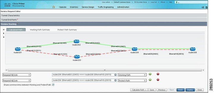
•![]() Working Path Summary—Click this button to view hop and link information for the working path.
Working Path Summary—Click this button to view hop and link information for the working path.
•![]() Protect Path Summary—Click this button to view hop and link information for the protect path.
Protect Path Summary—Click this button to view hop and link information for the protect path.
•![]() Add (or remove) path constraints by clicking the plus (or minus) icons to the right:
Add (or remove) path constraints by clicking the plus (or minus) icons to the right:
–![]() Required NE/Link—Specify network elements or links that traffic must pass through for either the working or the protect path.
Required NE/Link—Specify network elements or links that traffic must pass through for either the working or the protect path.
–![]() Excluded NE/Link—Specify network elements or links that traffic must not pass through for either the working or the protect path.
Excluded NE/Link—Specify network elements or links that traffic must not pass through for either the working or the protect path.
For more information about path constraints, see Working with Path Constraints.
Step 7 ![]() Go back over the various accordions to check and edit as necessary.
Go back over the various accordions to check and edit as necessary.
Step 8 ![]() Click Finish on the last accordion to complete the create service request operation.
Click Finish on the last accordion to complete the create service request operation.
The Service Request Manager window opens.
For information about the Service Request Manager elements and operations, see Chapter 8 "Managing Service Requests."
Guidelines for working with path constraints are provided in Working with Path Constraints.
An MPLS-TP service request that is in the DRAFT state can be modified. If a DRAFT MPLS-TP service request is modified, the new values will replace the previously saved values.
If the DRAFT service request is determined to be valid and complete so that all mandatory fields have been populated with valid values and the Save button is pressed, then the existing MPLS-TP service request will be moved to the REQUESTED state. The wizard is completed when you press the Finish button. Values to be auto-allocated from resource pools are allocated at that point.
If the DRAFT service request is determined to be incomplete so that not all mandatory fields have been populated or there are validation errors and the Save button is pressed, then the existing MPLS-TP service request will remain in the DRAFT state. The wizard is completed when you press the Finish button. Values to be auto-allocated from resource pools are NOT allocated at that point.
A service request in DRAFT state is marked by a white/orange work cone in the Service Request Manager.
Working with Path Constraints
Path constraints can be added to control the tunnel path when a service request is created or modified as shown in the procedure in Step 6 in the create procedure.
There are two ways to add path constraints:
•![]() Clicking a node or link on the routing diagram and clicking the plus sign. This adds a new path constraint to the working path by default. Change to Protect Path using the drop down if needed. Similarly, clicking the minus sign will remove the constraint.
Clicking a node or link on the routing diagram and clicking the plus sign. This adds a new path constraint to the working path by default. Change to Protect Path using the drop down if needed. Similarly, clicking the minus sign will remove the constraint.
•![]() If the node/link you want to exclude/include is not present in the diagram, you can use the selector next to Required NE/Link.
If the node/link you want to exclude/include is not present in the diagram, you can use the selector next to Required NE/Link.
Note ![]() If you change anything after the first path calculation, for example adding/removing constraints, switching protection on/off, etc., you will need to re-run path calculation by clicking Calculate Path.
If you change anything after the first path calculation, for example adding/removing constraints, switching protection on/off, etc., you will need to re-run path calculation by clicking Calculate Path.
Running Config Audit
A config audit task can be run against an MPLS-TP service requests to check that the configuration rolled onto a device by a particular service request is still present as expected.
To create a MPLS-TP Config Audit task, use the following steps:
Step 1 ![]() Choose Operate > Task Manager.
Choose Operate > Task Manager.
Step 2 ![]() Click Audit > Config Audit to open the Create Task window.
Click Audit > Config Audit to open the Create Task window.
Step 3 ![]() Modify the Name or Description fields as desired and click Next.
Modify the Name or Description fields as desired and click Next.
The service request selection window appears.
Step 4 ![]() Click Select SRs to add a service request and select schedule.
Click Select SRs to add a service request and select schedule.
Step 5 ![]() Click Submit.
Click Submit.
If successful, this adds the task to the list of created tasks in the Tasks window.
To view the task logs for the created tasks, in Task Manager select the created task and click Logs.
Running MPLS-TP Functional Audit
In an MPLS-TP Functional Audit, information is retrieved from source and destination endpoints to provide tunnel audit information.
This task only performs functional audit on service requests, which are not in one of the following states:
•![]() Draft
Draft
•![]() Closed
Closed
•![]() Requested
Requested
•![]() Invalid
Invalid
•![]() Failed Deploy
Failed Deploy
For more information on working with service requests, see Chapter 8 "Managing Service Requests."
To create a MPLS-TP Functional Audit task, use the following steps:
Step 1 ![]() Choose Operate > Task Manager.
Choose Operate > Task Manager.
Step 2 ![]() Click Audit > MPLS-TP Tunnel Functional Audit to open the Create Task window.
Click Audit > MPLS-TP Tunnel Functional Audit to open the Create Task window.
Step 3 ![]() Modify the Name or Description fields as desired and click Next.
Modify the Name or Description fields as desired and click Next.
The service request selection window appears.
Step 4 ![]() Click Select SRs to add a service request and select schedule.
Click Select SRs to add a service request and select schedule.
Step 5 ![]() Click Submit.
Click Submit.
If successful, this adds the task to the list of created tasks in the Tasks window.
To view the task logs for the created tasks, in Task Manager select the created task and click Logs.
Deploying an MPLS-TP Tunnel
The final step required to provision an MPLS-TP service request is the deploy the service request. This pushes the service request and the associated configuration updates to the network.
Note ![]() A service request in DRAFT state cannot be deployed.
A service request in DRAFT state cannot be deployed.
The deploy functionality is the same as for other Prime Fulfillment services. For instructions on how to deploy an MPLS-TP service request, see Deploying Service Requests.
Decommissioning
MPLS-TP service request configurations can be removed from the network using the decommissioning functionality within the Service Request Manager. Decommissioning will cause the previously deployed configurations to be removed from all tunnel endpoint and mid-point devices within the MPLS-TP tunnel path.
To decommission one or more service requests, see Chapter 8 "Managing Service Requests."
Sample Configlets
The configlets included in this section show the CLIs generated by Prime Fulfillment for particular services and features. Each configlet example provides the following information:
•![]() Service
Service
•![]() Feature
Feature
•![]() Devices configuration (network role, hardware platform, relationship of the devices and other relevant information)
Devices configuration (network role, hardware platform, relationship of the devices and other relevant information)
•![]() Sample configlets for each device in the configuration
Sample configlets for each device in the configuration
•![]() Comments.
Comments.
All examples in this section assume the presence of an MPLS-TP core.
Note ![]() The configlets generated by Prime Fulfillment are only the delta between what needs to be provisioned and what currently exists on the device. This means that if a relevant CLI is already on the device, it does not show up in the associated configlet.
The configlets generated by Prime Fulfillment are only the delta between what needs to be provisioned and what currently exists on the device. This means that if a relevant CLI is already on the device, it does not show up in the associated configlet.
This section provides sample configlets for MPLS-TP service provisioning in Cisco Prime Fulfillment.
It includes the following section:
•![]() MPLS-TP Working Tunnel Configlet (IOS)
MPLS-TP Working Tunnel Configlet (IOS)
MPLS-TP Working Tunnel Configlet (IOS)
Configuration
•![]() Service: MPLS-TP Working Tunnel
Service: MPLS-TP Working Tunnel
•![]() Feature: MPLS-TP configlet (IOS) for configuring MPLS-TP enabled nodes
Feature: MPLS-TP configlet (IOS) for configuring MPLS-TP enabled nodes
Configlets
 Feedback