Managing Pod Through Cisco VIM Unified Management

The following are the naming conventions used in the Cisco VIM UM

  1. Super Administrator (UM Admin): User having access to UM Admin profile

  2. POD Administrator: User having access to register a Pod in the system(Only UM can add new Pod Admin in the system)

  3. Pod users (Normal users): o All the users which are associated with the Pod. Full-pod-access: Role assigned to user which gives full access of a specific Pod(This has nothing to do with Pod Admins)

The following are the Key Points

  • User who are UM admin or Pod admin but not associated with any Pod are not counted in UM admin dashboard user count section

  • Only Pod Admins can register a new Pod

  • Every Pod must a user with “Full-pod-Access” role.

  • User cannot be revoked/delete if the users is the last user on the pod with “Full-Pod-Access” role.

  • User cannot be delete if user is a Pod admin or UM admin.

The following topics tell you how to install and replace Cisco Virtual Infrastructure Manager (VIM) nodes using Cisco VIM Insight.

Monitoring Pod Status

The unified management application manages the pods and displays the pod management action status with a cloud icon.

The following table displays a summary of the pod operation, the corresponding cloud-icon color, and the pod status.

Table 1. Pod Operation Status

Pod Operation

UM Icon-Color

Pod Status

Active cloud with no failures

Green

Active

Cloud installation or pod management operation is in progress

Blue

In-progress

Software update (auto) rollback is failed

Red

Critical Warnings

Pending commit post software update

Amber

Warning

Reconfigure failed (for any operation)

Red

Critical Warning

Update, commit, or Rollback failed

Red

Critical Warning

Power management operation fails

Amber

Warning

Management not reachable

Red

Not Reachable

Managing Hardware

Management of your Cisco VIM pods includes adding, removing, or replacing the nodes.

In a pod, multiple nodes cannot be changed at the same time. For example, if you want to replace two control nodes, you must successfully complete the replacement of the first node before you begin to replace the second node. Same restriction applies for addition and removal of storage nodes. Only, in case of Compute Nodes you can add or remove multiple nodes together.However, there must always be one active compute node in the pod at any given point. VNF manager stays active and monitors the compute nodes so that moving the VNFs accordingly as compute node management happens.


Note

When you change a control, storage, or compute node in a Cisco VIM pod using Insight, it automatically updates the server and role in the active blueprint, as a result, your OpenStack deployment changes. When a node is removed from Cisco VIM, sensitive data may remain on the drives of the server. Administrator advice you to use Linux tools to wipe the storage server before using the same server for another purpose. The drives that are used by other application server must be wiped out before adding to Cisco VIM.


Searching Compute and Storage Nodes

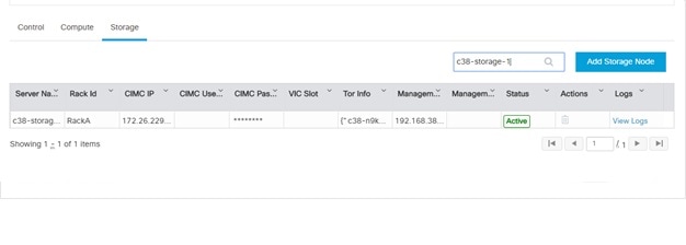
This functionality allows you to search the Compute and Storage nodes by server names only. The search result is generated or shows an empty grid if there are no results.

Figure 1. Search Storage Nodes

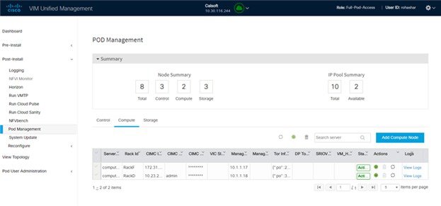
POD Management

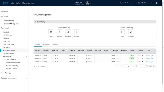
Cisco VIM allows the admin to perform pod life-cycle management from a hardware and software perspective. Cisco VIM provides the ability to power on/off compute node, add, remove or replace nodes based on the respective roles when the nodes of a given pod corrupts at times.

Figure 2. POD Management

Pod Management page has two sections–

  1. Node Summary: This section shows how many nodes are available and the detailed count of Control, Compute and Storage type.

  2. IP Pool Summary: This section shows the Total Pool Summary and the current available pool count.

The operations performed on the running pod are:

Replace Control Nodes: Double fault scenario is not supported. Only the replacement of one controller at a time is supported.


Note

If the TOR type is Cisco NCS 5500, an additional popup is displayed to enable the user to update splitter configuration before replacing the control node.

Add Computes/Storage Nodes: N-computes nodes can be replaced simultaneously; however at any given point, at least one compute node has to be active.


Note

If the TOR type is Cisco NCS 5500, an option is available to update the splitter cable configuration.

Power On/ Off compute Nodes: You can Power On or Power Off compute node. At least one compute node must be powered on.

Remove Compute/Storage Nodes: You can add one node at a time, when Ceph is run as a distributed storage offering.


Note

If TOR type is Cisco NCS 5500, an additional popup is displayed to enable the user to update the splitter cable configuration, before the removal of compute or storage node.

Add Pool: You can increase pool size at any time.

Managing Storage Nodes

Before you add or remove a storage node, review the following guidelines for Managing Storage Nodes.

  • Required Number of Storage Nodes: A Cisco VIM pod must have a minimum of three and a maximum of 20 storage nodes. If your pod has only two storage nodes, you cannot delete a storage node until you add another storage node. If you have fewer than three storage nodes, you can add one node at a time until you get to 20 storage nodes.

  • Validation of Nodes: When you add a storage node to a pod, Cisco VIM Insight validates that all the nodes in the pod meet the minimum requirements and are in active state. If you have a control or compute node in a faulty state, you must either correct, delete or replace that node before you can add a storage node.

  • Update Blueprint: When you add or delete a storage node, Insight updates the blueprint for the Cisco VIM pod.

  • Storage Node Logs: You can access the logs for each storage node from the link in the Log column on the Storage Nodes tab.

Adding Storage Node

Complete the following instructions to add a storage node:


Note

You cannot add more than one storage node at a time.


Before you begin
  • Remove the non-functional storage node from the pod. You can have maximum 20 storage nodes in a Cisco VIM pod.

  • Ensure that the server for the new storage node is in powered state in OpenStack for C Series.

Procedure

Step 1

In the navigation pane, choose Post-Install > Pod Management > Storage.

Step 2

Click on Add Storage node button on the Storage tab. A popup will open where you can provide information about the new Storage node.

Step 3

For C Series, add the following details:

  • Server Name: Name for the Storage Server to be added.

  • Rack ID: Enter the Rack ID. (Accepts String format).

  • CIMC IP: Enter the CIMC IP.

  • CIMC User Name: User name for the CIMC.

  • CIMC Password: Enter the password for the CIMC

  • VIC Slot: Enter the VIC Slot (Optional).

  • ToR switch info:Mandatory if ToR is configured as True

    • Management IPv6: Enter IPv6 Address.

Step 4

For B Series, add the following details:

  • Server Name: Name for the Storage Server to be added.

  • Rack ID: Enter the Rack ID. (Accepts String format).

  • Rack Unit ID: Enter the Rack Unit ID.

  • Management IPv6: Enter IPv6 Address.
    Note 

    Cancel will discard the changes and popup will be closed

If all mandatory fields are filled in correctly then Add Storage button will be enabled.

Step 5

Click Initiate Add Storage. Add node initialized message will be displayed.

Step 6

To view logs, click View logs under Logs column.

The status of the POD will change to Active.
Step 7

Two kinds of failure may occur:

  • Add Node Pre-Failed: When addition of node failed before the bare-metal stage (step 4) the Active Blueprint will be modified but the Node is not yet added in the Cloud. If you press X Icon, then Insight will delete the node information form the Blueprint and the state would be restored.

  • Add Node Post-Failed: When addition of node failed after the bare-metal stage (step 4) the Active Blueprint will be modified and the node is registered in the cloud. If you press X Icon, then Insight will first delete the node from the Blueprint and then node removal from cloud would be initiated.

You can view the logs for this operation under Logs column.


Deleting Storage Node

You cannot delete more than one storage node at a time.

Procedure

Step 1

In the Navigation pane, choose Post-Install > POD Management > Storage.

Step 2

Click X adjacent to the storage node you want to delete.

Yor can delete a storage node with Force option for hyper-converged POD. The Force option is useful when VM’s are running on the node.
Step 3

Node Removal Initiated successfully message will be displayed.

To view logs, click View logs under logs column.

  • If the Storage Node is deleted successfully, the storage node will be removed from the list under Add/Remove storage Node.

  • In deletion failed, a new button Clear Failed Nodes will be displayed. Click Clear Failed Nodes to remove the node form cloud and Blueprint.


Managing Compute Nodes

Before you add or remove a compute node, review the following guidelines:

  • Required Number of Compute Nodes: Cisco VIM pod must have a minimum of one compute node and a maximum of 61 compute nodes (with 3 ceph nodes). If your pod has only one compute node, you cannot delete that node until you add another compute node.

  • Update Blueprint: When you add or remove a compute node, Insight updates the blueprint for the Cisco VIM pod.

  • Compute Node Logs: You can access the Logs for each compute node from the link in the Log column on the Compute Nodes table.

Adding Compute Node

Add IP Pool

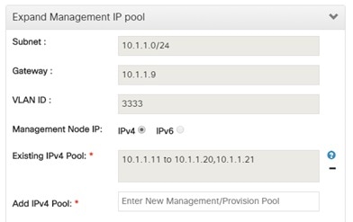
If all the existing pool size is already used, then you need to increase the pool size. On the Add compute or Add storage popup, Click Expand Management IP pool to add a new Pool.

Complete the instructions, to add a compute node:

Before you begin

Ensure that the server for the new compute node is in powered state in OpenStack. You can add more than one compute node at a time.

Procedure

Step 1

In the navigation pane, click Post-Install > Pod Management > Compute.

Step 2

Click Add Compute Node on the Compute tab a popup opens . Add the required information in the popup. To add another node clcik Add Another Node if you planned to add another compute node OR hit Initiate Add Compute if you so not plan to add any more compute node. If you hit “Add Another Node” button, the existing form will be emptied. You will have to fill the information for the new compute node and then repeat step 1. You may use Previous and Next button to navigate among different added node information.

Step 3

For C Series, add the following details:

  • Server Name: Name for the Compute Server.

  • Rack ID: Enter the Rack ID. (Accepts String format).

  • CIMC IP: Enter the CIMC IP.

  • CIMC User Name: User name for the CIMC.

  • CIMC Password: Enter the password for the CIMC.

  • VIC Slot: Enter the VIC Slot (Optional).

  • ToR switch info: Mandatory if configured ToR is true.

  • DP ToR switch info: Enter input as string format.

  • SRIVO ToR info : Enter input as string format.

  • Management IPv6 : Enter IPv6 Address.

Step 4

For B Series, add the following details:

  • Server Name: Name for the Storage Server to be added.

  • Rack ID: Enter the Rack ID. (Accepts String format).

  • Rack Unit ID: Enter the Rack Unit ID.

  • Chassis ID: Enter the Chassis ID. Range for Chassis ID is 1-24.

  • Blade ID: Enter the Blade ID. Range for Blade ID is 1-8.

  • CIMC Password: Enter the CIMC Password.

  • Management IPv6: Enter IPv6 address.

    If all mandatory fields are filled in correctly then click Save

Note 

Add Compute process can initiate multiple add of compute nodes. Fill in the mandatory fields to save new compute node or press cancel to exit message will be displayed.

Fields of Pod management will remain mandatory for user input based on setup-data.

Step 5

You may perform one among these steps mentioned below:

  • Clicking Cancel displays the compute node information listed in the table and Add Compute Node button is enabled.

  • If you feel you have filled in a wrong entry for the compute node information, click Delete. This will delete the entry from the table as this information is not added in the Blueprint.

  • Click Initiate Add Compute, displays Add node initialized message.

Step 6

To view logs, click View logs under Logs column. The status of the POD will change to Active.

Step 7

Two kinds of failure may occur:

  • Add Node Pre-Failed: When addition of node failed before the bare-metal stage (step 4) the Active Blueprint will be modified but the Node is not yet added in the Cloud. If you press X Icon, then Insight will delete the node information form the Blueprint and the state would be restored.

  • Add Node Post-Failed: When addition of node failed after the bare-metal stage (step 4) the Active Blueprint will be modified and the node is registered in the cloud. If you press X Icon, then Insight will first delete the node from the Blueprint and then node removal from cloud would be initiated.

You can view the logs for this operation under Logs column.


Deleting Compute Node

Compute node is deleted due to a hardware failure. You can delete one compute node at a time.


Note

If your pod has only one compute node, you cannot delete that node until you add another compute node.
Procedure

Step 1

In the navigation pane, choose Post-Install > POD Management > Compute.

Step 2

Click X for the compute node to be deleted. To remove multiple compute nodes, choose the target compute nodes which is on the extreme left column, then click Trash to remove multiple computes.

You can delete a compute node with Force option which is useful when VM’s are running on the node.

"Node removal initiated successfully" message is displayed.
Step 3

To view the Logs, click View logs under Logs column.

  • If compute nodes are deleted successfully, you cannot view the compute node in the list under Add or Remove Compute Node.

  • If Compute Note is deleted, a new button Clear Failed Nodes is displayed.

Step 4

Click Clear Failed Nodes to remove the node form Cloud and Blueprint.


Managing Control Nodes

Before you replace a control node, review the following guidelines:

  • Required Number of Control Nodes: A Cisco VIM pod must have three control nodes and you can only replace one node at a time.

  • Validation of Nodes: When you replace a control node, Cisco VIM Insight validates if all the other nodes in the pod meet the minimum requirements and are in active state. If you have a storage or a compute node in a faulty state, you must correct the faulty state or delete or replace that node before you can replace the control node.

  • Update Blueprint: When you replace a control node, Insight updates the Active blueprint for the Cisco VIM pod.

  • Control Node Logs: You can access the logs for each control node from the link in the Logs column of Control Nodes table.

Replacing Control Node

You can replace only one control node at a time.

Procedure

Step 1

In the navigation pane, click Post-Install > Pod Management > Control..

Step 2

Click (Spin) icon. A confirmation pop-up appears, Click Proceed to continue.

You can replace a control node with Force option for Micropod. The Force option is useful when VM’s are running on the node.

Step 3

If you want to edit a specific control node before replace, click Edit to update the changes.

Step 4

On success, Replace Node Initiated successfully message is displayed.

Step 5

You can view the logs in the Logs column on the Control Nodes table.


What to do next

If the replacement of the control node fails, do the following:

  • Click the link in the Logs column.

  • Check the logs to determine the cause of the failure.

  • Correct the issue and attempt to replace the control node again.

Power Management

Compute node can be powered on or powered off from the Compute Tab in Pod Management section. There is a power button associated with each compute with information provided as tooltip when you hover on that icon.

Following are the steps to power on/off multiple compute node:

  1. Click Power button located to the left of delete button.

  2. Choose the compute nodes by selecting the check box, the corresponding power button gets enabled.

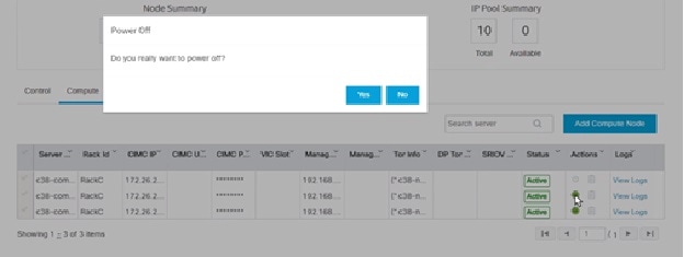
Power On a Compute Node

Following are the steps to power on the compute node:

  1. Click the Compute tab.

  2. In the Pod Management area, check the check box corresponding to the Compute node that you want to power on.

    Note

    The Power button of a Compute node is enabled only after you select the Compute node.


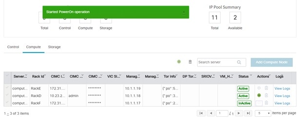
    Figure 3. Powering On a Compute Node
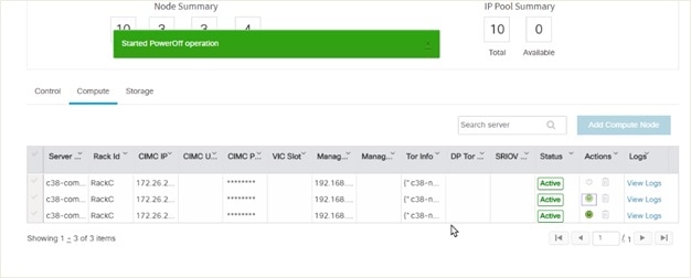
  3. Under the Actions column, click the Power button of the Compute node. It may take a few minutes for the Compute node to power on. The tooltip of the power button displays the status of the Compute node. Once the compute node is powered on, the Power button stops blinking and its color changes to green.

Figure 4. Power On Operation

You can add a Compute node only once a power on task is complete.

Powering Off Compute Node


Note

You cannot power off all the Compute nodes. There must be at least one Compute node that is in the On state.


Follow these steps to power off a Compute node:

  1. Click the Compute tab.

  2. In the Pod Management area, under the Actions column, click the Power button of the Compute node that you want to power off.

  3. Click Yes in the confirmation dialog box.

    It may take a few minutes for the Compute node to power off. The tooltip of the power button displays the status of the Compute node. Once the compute node is powered off, the Power button stops blinking and its color changes to grey.


Note

If there is only one compute node in the grid, and you try to power off it, a message Last compute node can’t be powered off is displayed. Also, when you power off the last available compute node in the list of nodes, then the message At least one compute node should be powered on is displayed.


Multiple compute power/ delete/ reboot operation

You can perform power, delete, and reboot operation on multiple compute nodes using the global buttons located at the top of grid. To enable this operation, select at least one compute node.


Rebooting Compute Node

To reboot the compute node, follow the below steps:

  1. Click on Compute tab.

  2. In the Pod Management pane, under the Actions column, click Reboot of the compute node that you want to reboot.

  3. Click Yes in the confirmation dialog box, to perform reboot. You can reboot a compute node with Force option which is useful when VM’s are running on the node.

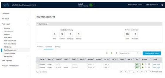
Multiple compute power/ delete/ reboot operation

You can perform power, delete, and reboot operation on multiple compute nodes using the global buttons located at the top of grid. To enable this operation, select at least one compute node.

Figure 5. Pod Management

Searching Compute and Storage Nodes

This functionality allows you to search the Compute and Storage nodes by server names only. The search result is generated or shows an empty grid if there are no results.

Figure 6. Search Storage Nodes

Managing Software

Software management of your Cisco VIM pods includes software update, reconfigure of openstack services and password, etc.

VIM Software Update

As part of the lifecycle management of the cloud, VIM has the ability to bring in patches (bug fixes related to code, security, etc.), thereby providing cloud management facility from software point of view. Software update of the cloud is achieved by uploading a valid tar file, following initiation of a System Update form the Insight as follows:

Procedure


Step 1

In the Navigation pane, click Post-Install > System Update.

Step 2

Click Browse and select the valid tar file.

Step 3

Click Open.

Step 4

Click Upload and Update.

Update started Successfully message will be displayed.
Step 5

Update status will be shown as ToUpdate.

Click the hyperlink to view the reconfigure logs for install logs.

Reconfigure status will be available on the page or the dashboard under POD Operation details.


What to do next

System Update has been initiated message will be displayed. Logs front-ended by hyperlink will be in the section below in-front of Update Logs which shows the progress of the update. During the software update, all other pod management activities will be disabled. Post-update, normal cloud management will commence. Once update has completed you will see the status of update in the box below.

If log update fails, Auto-RollBack will be initiated automatically.

If log update is successful, you will have two options to be performed:

  1. Commit—To proceed with the update.

  2. RollBack—To cancel the update.

If Auto-rollback fails during software update fails through Insight UI, it is advised that the administrator contact Cisco TAC for help. Do not re-try the update or delete the new or the old installer workspace.

If the update is successful and reboot is required for at least one compute node:

  • Only commit or rollback is allowed.

  • Following operations are not permitted:

    • Reconfigure

    • System update

    • Pod management


Note

You can reboot the node, only after the commit or rollback operation.
.

Reconfigure Openstack Passwords

There are two options to regenerate the passwords:

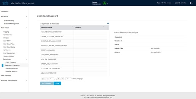
  • Regenerate all passwords: Click Regenerate all passwords checkbox and click Set Password. This will automatically regenerate all passwords in alphanumeric format.

  • Regenerate single or more password: This will set a specific password by doing an inline edit for any service like Horizon's ADMIN_USER_PASSWORD. Double click on the filed under Password and enter the password to enable Set Password button.

During the reconfiguration of password, all other pod management activities will be disabled. Post-update, normal cloud management will commence. If the reconfigure of the password fails, all subsequent pod management operations will be blocked. It is advised to contact Cisco TAC to resolve the situation through CLI.

Reconfigure OpenStack Services, TLS Certificates, and ELK Configurations

Cisco VIM supports the reconfiguration of OpenStack log level services, TLS certificates, and ELK configuration. Following are the steps to reconfigure the OpenStack and other services:

Procedure


Step 1

In the navigation pane, click Post-Install > Reconfigure Openstack Config.

Step 2

Click the specific item that you want to change and update. For example: to update the TLS certificate click the path to the certificate location.

Step 3

Enter Set Config to commence the process.


What to do next

During the reconfiguration process, all other pod management activities are disabled. Post-update, normal cloud management commences. If reconfigure of OpenStack Services fails, all subsequent pod management operations are blocked. Contact, Cisco TAC to resolve the situation through CLI.

Reconfiguring CIMC Password through Unified Management

Cisco VIM allows you to Update the cimc_password in the CIMC-COMMON section, and/or the individual cimc_password for each server and then run the update password option.

You need to match the following Password rule to update the Password:

  • Must contain at least one lower case letter.

  • Must contain at least one upper case letter.

  • Must contain at least one digit between 0 to 9.

  • One of these special characters !$#@%^-_+=*&

  • Your password has to be 8 to 14 characters long.

Before you begin

You must have a C-series pod up and running with Cisco VIM to reconfigure CIMC password.

Note

Reconfigure CIMC password section will be disabled if the pod is in failed state as indicated by ciscovim install-status.


Procedure


Step 1

Log-in to CISCO VIM Insight.

Step 2

In the navigation pane, select Post-Install.

Step 3

Click Reconfigure CIMC Password.

Step 4

You can reconfigure the CIMC Password at global level by adding new CIMC_COMMON Password or to reconfigure CIMC Password for individual servers double click the server password you want to edit.

Step 5

Click Reconfigureto initiate reconfigure process.


Reconfigure Optional Services

Cisco VIM offers optional services such as heat, migration to Keystone v3, NFVBench, NFVIMON, etc, that can be enabled post-pod deployment. These services can be enabled in one-shot or selectively.

Listed below are the steps to enable optional services:

Procedure


Step 1

In the Navigation pane, click Post-Install > Reconfigure Optional Services.

Step 2

Choose the right services and update the fields with the right values.

Step 3

Click Offline validation. Once offline validation is successful.

Step 4

Click Reconfigure to commence the process.

During the reconfiguration process, all other pod management activities will be disabled. Post-update, normal cloud management will commence.

If reconfigured OpenStack Services fail, all subsequent pod management operations are blocked. Contact Cisco TAC to resolve the situation through CLI.

Note 

All reconfigure operation features contain repeated re-deployment option set to true or false.

  • Repeated re-deployment true - Feature can be re-deployed again.

  • Repeated re-deployment false- Deployment of feature allowed only once.

Deployment Status :

Optional Features

Repeated re-deployment Option

APICINFO

True

EXTERNAL_LB_VIP_FQDN

False

EXTERNAL_LB_VIP_TLS

False

INSTALL_MODE

True

HTTP_PROXY & HTTPS_PROXY

True

LDAP

True

NETWORKING

True

NFVBENCH

False

NFVIMON

False

PODNAME

False

PROVIDER_VLAN_RANGES

True

SWIFTSTACK

True

SYSLOG_EXPORT_SETTINGS

False

TENANT_VLAN_RANGES

True

TORSWITCHINFO

False

VIM _ ADMINS

True

VMTP

False

VTS_PARAMETERS

False

AUTOBACKUP

`

True

Heat

False

Keystone v3

False

Cobbler

True

ES Remote Backup

True

CVIMMON

True

NETAPP_SUPPORT

True

Enable Read-only OpenStack Admins

True


Reconfiguring Optional Features Through Unified Management

Procedure


Step 1

Log-in to Cisco VIM UM.

Step 2

In the Navigation pane, expand the Post-Install Section.

Step 3

Click Reconfiguring Optional Feature through UM.

Step 4

On the Reconfiguring Optional Feature through UM page of the Cisco VIM UM, complete the following fields:

Name

Description

Heat check box

  • Enable Heat.

  • Click Offline Validation .

  • When Offline Validation is successful, click Reconfigure to commence the process.

Enable Read-only OpenStack Admins checkbox

  • Check/uncheck Enable Read-only OpenStack Admins

  • Click Offline Validation

When Offline Validation is successful, click

Reconfigure to commence the process.

Keystone v3 check box

  • Enable Keystone v3.

  • Click Offline Validation .

  • When Offline Validation is successful, click Reconfigure to commence the process.

ENABLE_ESC_PRIV

  • Enable ENABLE_ESC_PRIV .

  • Click Offline Validation .

  • When Offline Validation is successful, click Reconfigure to commence the process.

Autobackup check box

  • Enable/Disable Autobackup.

  • Click Offline Validation .

  • When Offline Validation is successful, click Reconfigure to commence the process.

External LB VIP TLS check box

  • Enable External LB VIP TLS.

  • Click Offline Validation .

  • When Offline Validation is successful, click Reconfigure to commence the process.

External LB VIP FQDN check box

  • Enter Input as a string.

  • Click Offline Validation .

  • When Offline Validation is successful, click Reconfigure to commence the process.

Pod Name

  • Enter Input as a string.

  • Click Offline Validation .

  • When Offline Validation is successful, click Reconfigure to commence the process.

Tenant Vlan Ranges

  • Augment tenant vlan ranges input. For Example: 3310:3315.

  • Click Offline Validation .

  • When Offline Validation is successful, click Reconfigure to commence the process.

Provider VLAN Ranges

  • Enter input to tenant vlan ranges. For Example: 3310:3315.

  • Click Offline Validation .

  • When Offline Validation is successful, click Reconfigure to commence the process.

Install Mode

  • Select Connected or Disconnected, any one form the drop-down list.

  • Click Offline Validation .

  • When Offline Validation is successful, click Reconfigure to commence the process.

Registry Setup Settings checkbox

For Registry Setup:

  • Enter the Registry User Name. It is a mandatory field

  • Enter the Registry Password. The minimum length of the password is three.

  • Enter the Registry Email. It is a mandatory field.

  • Enter the Registry Name. For example, Registry FQDN name. It is a mandatory field, only when SDS is enabled.

  • Click Offline Validation

  • If offline validation is successful, click Reconfigure to commence the process.

.

Syslog Export Settings

Following are the options for Syslog Settings:

Remote Host

Enter Syslog IP Address.

Facility

Defaults to local5

Severity

Defaults to debug

Clients

Defaults to ELK

Port

Defaults to 514 but is modified by the User.

Protocol Supports only UDP

Click Offline Validation .

  • When Offline Validation is successful, click Reconfigure to commence the process.

Configure ToR checkbox

True or False. Default is false.

ToR Switch Information

Click + to add information for ToR Switch.

Name

Description

Name

ToR switch name.

Username

ToR switch username.

Password

ToR switch Password.

SSH IP

ToR switch SSH IP Address.

SSN Num

ToR switch ssn num. output of show license host-id.

VPC Peer Keepalive

Peer Management IP. You need not define if there is no peer.

VPC Domain

Need not define if there is no peer.

VPC Peer port

Interface for vpc peer ports.

VPC Peer VLAN Info

vlan ids for vpc peer ports (optional).

BR Management Port Info

Management interface of the build node.

BR Management PO Info

Port channel number for the management interface of the build node.

Click Save

  • Click Offline Validation .

  • When Offline Validation is successful, click Reconfigure to commence the process.

Note 

When setup data is ACI VLAN with TOR then reconfigure options are:

TORSwitch Information mandatory table if you want to enter ToR information

Click + to add information for ToR Switch.

Name

Description

Host Name

ToR switch name.

VPC Peer Keepalive

Peer Management IP.

VPC Domain

Do not define if there is no

Node ID Integer, unique across all switches

Click Save

  • Click Offline Validation .

  • When Offline Validation is successful, click Reconfigure to commence the process.

NFV Bench

Enable check box which by default is false.

Add Tor info connected to switch:

  • Select a TOR Switch and Enter the Switch name.

  • Enter the port number. For example: eth1/5

  • NIC Ports: INT1 and INT2 optional input, enter the 2 port numbers of the 4-port 10G Intel NIC at the management node used for NFVBench.

  • Click Offline Validation .

  • When Offline Validation is successful, click Reconfigure to commence the process.

Note 

If ToR is already present in Setup-data or already deployed. Then no need add Tor info, by default ToR info switchname is mapped in NFV bench.

Swiftstack

SwiftStack is only supported with Keystone v2. If you select Keystone v3, swiftstack will not be available for configuration.

Cluster End Point

IP address of PAC (proxy-account-container) endpoint.

Admin User

Admin user for swift to authenticate in keystone.

Admin Tenant

The service tenant corresponding to the Account-Container used by Swiftstack.

Reseller Prefix

Reseller_prefix as configured for Keystone Auth,AuthToken support in Swiftstack E.g KEY_

Admin Password

swiftstack_admin_password

Protocol drop-down list

http or https

  • Click Offline Validation .

  • When Offline Validation is successful, click Reconfigure to commence the process.

LDAP with Keystone v3

Domain Name field

Enter the Domain name.

Object Class for Users field

Enter a string as input.

Object Class for Groups

Enter a string.

Domain Name Tree for Users

Enter a string.

Domain Name Tree for Groups field

Enter a string.

Suffix for Domain Name field

Enter a string.

URL field

Enter a URL with port number.

Domain Name for Bind User field

Enter a string.

Password field

Enter Password as string format.

User Filter

Enter filter name as string.

User ID Attribute

Enter a string.

User Name Attribute

Enter a string.

User Mail Attribute

Enter a string.

Group Name Attribute

Enter a string.

  • Click Offline Validation .

  • When Offline Validation is successful, click Reconfigure to commence the process.

NFV Monitoring

Followings are the field values for NFV Monitoring:

Master Admin IP field.

Enter Input as IP format.

Collector Management IP field

Enter Input as IP format.

Collector VM1 info
Host Name field

Enter Host Name as a string.

CCUSER password field

Enter Password.

Password field

Enter password.

Admin IP field

Enter Input as IP format.

Management IP field

Enter Input as IP format.

Collector VM2 info
Host Namefield

Enter a string.

CCUSER field

Enter Password.

Management IP field

Enter Input as IP format.

Dispatcher
Rabbit MQ Username Field

Enter a string.

  • Click Offline Validation .

  • When Offline Validation is successful, click Reconfigure to commence the process.

VTS Parameter

Following are the fields to reconfigure for VTS parameters

VTC SSH Username field.

Enter the string.

VTC SSH Username field.

Enter the password.

  • Click Offline Validation .

  • When Offline Validation is successful, click Reconfigure to commence the process.

VMTP

Check one of the check boxes to specify a VMTP network:

  • Provider Network

  • External Network

For the Provider Network complete the following:

Network Name field.

Enter the name for the external network.

IP Start field.

Enter the starting floating IPv4 address.

IP End field.

Enter the ending floating IPv4 address.

Gateway field

Enter the IPv4 address for the Gateway.

DNS Server field.

Enter the DNS server IPv4 address.

Segmentation ID field.

Enter the segmentation ID.

Subnet

Enter the Subnet for Provider Network.

For External Network fill in the following details:

Network Name field.

Enter the name for the external network.

Network IP Start field.

Enter the starting floating IPv4 address.

Network IP End field.

Enter the ending floating IPv4 address.

Network Gateway field

Enter the IPv4 address for the Gateway.

DNS Server field.

Enter the DNS server IPv4 address.

Subnet

Enter the Subnet for External Network.

  • Click Offline Validation .

  • When Offline Validation is successful, click Reconfigure to commence the process.

Networking

In Reconfigure optional services networking, you can reconfigure IP tables, or add http_proxy/https_proxy.

To reconfigure networking, update the relevant information:

IP Tables

Click Add(+) to add a table. Enter input as subnet format.

E.g. 12.1.0.1/2

http_proxy_server

Enter HTTP_PROXY_SERVER

E.g. <a.b.c.d:port>

https_proxy_server

Enter HTTP_PROXY_SERVER

E.g. <a.b.c.d:port>

  • Click Save.

  • Click Offline Validation.

  • When Offline Validation is successful, click Reconfigure to commence the process.

APICINFO

Note 

Reconfigure optional services only APIC hosts can be reconfigure.

To reconfigure APICINFO, follow the process:

  • Enter input for APIC hosts format. <ip1|host1>:[port] or eg.12.1.0.12

  • Click Save.

  • Click Offline Validation.

  • When Offline Validation is successful, click Reconfigure to commence the process.

Note 

APIC hosts can be reconfigure minimum 1 host and max 3 but not 2 hosts.

Vim_admins

To reconfigure vim_admins, follow the process:

  • To add a new root user, Click + and add the Username and admin hash password (Starting with $6). At least, one Vim Admin must be configured, when Permit root login is false.

  • To remove the existing user, Click -.

  • When Offline Validation is successful, click Reconfigure to commence the process.

Cobbler

To reconfigure Cobbler, follow the process:

  • Generate the admin password hash by executing the below command:
    
    python -c 'import crypt; print crypt.crypt
    ("<plaintext_strong_password>")'
     on the management node.
  • Validate that the admin_password_hash starts with '$6'

  • Enter Admin Password Hash.

  • Click Offline Validation.

  • When Offline Validation is successful, click Reconfigure to commence the process.

ES Remote Backup

To reconfigure Elastic Search Remote Backup:

Service field displays NFS by default, if the remote NFS server is used.

  • Enter the Remote Host, which is IP of the NFS server.

  • Enter the Remote Path. . It is the path of the backup location in the remote server.

  • Click Offline Validation.

  • If Offline Validation is successful, click Reconfigure to commence the process.

CVIMMON

To reconfigure CVIMMON, enter the following details:

  • Enter the Low Frequency, such that it is higher than medium frequency. Minimum value is 1 minute. By default, it is set to 1 minute.

  • Enter the Medium Frequencysuch that it is more than high frequency. Minimum value is 30 seconds. By default, it is set to 30 seconds.

  • Enter the High Frequency such that the minimum value is 10 seconds. By default, it is set to 10 seconds.

  • Click Offline Validation.

  • If Offline Validation is successful, click Reconfigure to commence the process.

NETAPP_SUPPORT

To reconfigure NETAPP_SUPPORT, enter the following details:

  • Select the Server Port. It is the port of NetApp management or API server. Select 80 for HTTP and 443 for HTTPS.

  • Select the Transport Type of the NetApp management or API server. It can be HTTP or HTTPS.

  • Select the NetApp Cert Path. It is the root ca path for NetApp cluster, only if protocol is HTTPS.

  • Click Offline Validation.

  • If Offline Validation is successful, click Reconfigure to commence the process.


Pod User Administration

Cisco VIM UM offers Users (Pod Admins or Pod Users) to manage Users and roles that are associated with them.

Managing Roles

User can create multiple Roles and assign them to other pod users. System has a default role that is named as Full-Pod-Access which is assigned to the person who registers the Pod.

Manage Roles

Procedure


Step 1

Click Login as POD User.

Step 2

Navigate to Pod User Administration and click Manage Roles. By default you see full-pod-access role in the table.

Step 3

Click Add New Role to create a new role.

Step 4

Complete the following fields in the Add Roles page in Cisco VIM UM:

Field Name

Field Description

Role

Enter the name of the role.

Description

Enter the description of the role.

Permission Check the Permission check box to select the permission.
Click Save. Once the Blueprint is in Active state all the permissions are same for C-series and B-series Pods other than Reconfigure CIMC Password which is missing for B-series Pod.
Note 

Permissions are divided in the granular level where viewing Dashboard is the default role that is implicitly added while creating a role.

Note 

Permissions are divided in the granular level where viewing Dashboard is the default role that is implicitly added while creating a role.


Managing Users

This section allows you to add the users. It shows all the users associated with the Pod. You can check the online status of all the user. ClickRefresh on upper right corner to check the status.

To add a new user:

Procedure


Step 1

Click Login as POD User.

Step 2

Navigate to POD User Administration and click Manage Users .

Step 3

Click Add Users to add a new user.

Step 4

Complete the following fields in the Add Users pane of the Cisco VIM Insight:

Field Name

Field Description

Email ID

Enter the Email ID of the User.

User Name

Enter the User Name if the User is new. If the User is already registered to the Insight the User-Name gets auto-populated.

Role

Select the Role from the drop-down list.

Step 5

Click Save Once the Blueprint is in Active state all the permissions are same for C-series and B-series Pods other than Reconfigure CIMC Password which is missing for B-series Pod.


Revoke Users

User with Full-Pod-Access or Manage Users permission can revoke other users from the specific Pod.

To revoke users:

Procedure


Step 1

Click Undo icon. A confirmation pop up will appear.

Step 2

Click Proceed to continue.

Note 

Self revoke is not permitted. After revoking the another user, if the user is not associated with any other pod then the revoked user will be auto deleted from the system.


Edit Users

User with Full-Pod-Access or Manage Users permission can edit other user’s permission for that specific Pod.

To edit user’s permission

Procedure


Step 1

Click Edit icon.

Step 2

Update the permission.

Step 3

Click Save. The Grid will get refreshed automatically.


Managing Root CA Certificate

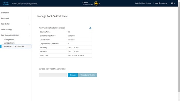
You can update the CA Certificate during the registration of the POD. Once, logged in as POD User and if you have the permission to update the certificate you can view under POD User Administration>> Manage Root CA Certificate.

To update the Certificate:

Procedure


Step 1

Click Login as POD User

Step 2

Navigate to POD User Administration>>Manage Root CA certificate.

Step 3

Click Browse and select the certificate that you want to upload.

Step 4

Click Upload.

  • If the certificate is Invalid, and does not matches with the certificate on the management node located at (var/www/mercury/mercury-ca.crt) then Insight reverts the certificate which was working previously.

  • If the Certificate is valid, Insight runs a management node health check and then update the certificate with the latest one.

Note 

The CA Certificate which is uploaded should be same as the one which is in the management node.