Table Of Contents
Capturing and Decoding Packet Data
Working with Alarm Capture Triggers
Capturing Using an Address Filter
Capturing Using a Protocol Filter
Capturing Using a Custom Filter
Viewing Packet Decode Information
Viewing Packets in the Packet Browser
Filtering Packets Displayed in the Capture Decode Window
Viewing Protocol Decode Information
Downloading Capture Buffer to a File
Setting Up Custom Capture Filters
Creating Custom Capture Filters
Tips for Creating Custom Capture Filter Expressions
Editing Custom Capture Filters
Deleting Custom Capture Filters
Setting Up Custom Decode Filters
Creating Custom Decode Filters
Tips for Creating Custom Decode Filter Expressions
Deleting Custom Decode Filters
Capturing and Decoding Packet Data
The Capture tab has features for setting up, controlling, and displaying packet capture data.
The overall procedure for working with capture settings is:
1. Use the Settings option to configure capture settings and filters. (See the "Configuring Capture Settings" section.)
2. Use the Custom Filters option to create and save specialized filters when capturing data. (See the "Setting Up Custom Capture Filters" section.)
3. After packets are captured, use the Decode option to decode and view captured packets. See:
–The "Viewing Packet Decode Information" section.
–The "Viewing Protocol Decode Information" section.
4. Use the Download option to save and download the capture buffer. (See the "Downloading Capture Buffer to a File" section.)
Configuring Capture Settings
You must set up the capture settings and filters before starting the actual capture. After packets are captured, you can use decode filters to further narrow down the packets displayed in the Packet Decoder window.
Step 1 Click the Capture tab.
Step 2 Click Settings.
The Capture Settings Dialog Box (Figure 6-1) is displayed.
Figure 6-1 Capture Settings Dialog Box
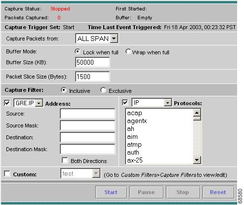
In the top of the dialog box, there are four status indicators.
Step 3 Enter information in the Capture Settings Dialog Box (Table 6-1) as appropriate.
Step 4 In the Capture Filter pane, select inclusive or exclusive filter mode. (Inclusive filters capture only packets that match the filter conditions; exclusive captures exclude those packets that match the filter conditions.)
Step 5 Select one of the following check boxes to enable the applicable filter types:
•Address to filter traffic based on a type of IP, IPIP4, IPv6, GRE.IP, or MAC address. (See the "Capturing Using an Address Filter" section.)
•Protocol to filter traffic based on specific protocols. (See the "Capturing Using a Protocol Filter" section.)
•Custom to use a customized filter. (See the "Capturing Using a Custom Filter" section.)
Note To create a custom capture filter, see the "Setting Up Custom Capture Filters" section.
Step 6 Do one of the following:
•To start the capture, click Start.
•To temporarily pause a running capture, click Pause.
•To stop a running capture and clear the capture buffer, click Stop.
•To discard and reset all of your selections and start over, click Reset.
Working with Alarm Capture Triggers
You can create two types of capture triggers from the Setup > Alarms section—start or stop. Only one capture trigger may be set at a time. For the capture triggers to work, you must set the capture buffer settings in advance. For more information on setting capture triggers, see the "Setting Alarm Thresholds" section.
For start capture triggers, the capture buffer should be in a paused state. If the buffer is stopped or running, a start capture trigger does not work. For optimal performance, we recommend that you set the buffer mode to Lock when full.
For stop capture triggers, the capture buffer should be running. If the buffer is paused or stopped, a stop trigger does not work. For optimal performance, we recommend that you set the buffer mode to Wrap when full.
Capturing Using an Address Filter
If you selected the Address check box, enter information in the Capture Settings Address Filter Dialog Box (Table 6-2) as appropriate.
Note When filtering on tunnel addresses such as IPIP4 or GRE.IP, the filters will match the addresses on the inner and outer IP header.
Capturing Using a Protocol Filter
If you selected the Protocol check box, select one or more protocols to capture from the list.
Capturing Using a Custom Filter
Step 1 Select the Custom check box.
Note The Address Filter and Protocol Filter check boxes are disabled if you select the Custom Filter check box and vice versa.
Step 2 Select a custom capture filter from the list.
Note If the list is empty, see the "Creating Custom Capture Filters" section for instructions on creating custom capture filters.
Step 3 (Optional.) To view or edit the selected custom capture filter, select
Custom Filters > Capture Filters.
For example, to capture only HTTP and HTTPS packets in the 111.122 Class B network, do the following:
Step 1 Select the Inclusive check box.
Step 2 Select the Address check box.
Step 3 Select the IP button.
Step 4 Select the Both Directions check box.
Step 5 In the Source, enter 111.122.0.0.
Step 6 In the Source Mask, enter 255.255.0.0.
Step 7 Select the Protocol check box.
Step 8 Press Shift-Click to select HTTP and HTTPS from the list.
Viewing Packet Decode Information
After some packets have been captured in the buffer, you can use the Packet Decoder to view the packet contents.
Note If several people use the Packet Decoder simultaneously, they see the same capture buffer.
The Packet Decoder window has three parts:
•Packet browser pane (top of window).
•Protocol decode (See the "Viewing Protocol Decode Information" section).
•Packet hexadecimal dump.
Step 1 Click the Capture tab.
Step 2 Click Decode.
The Packet Decoder dialog box is displayed. Packet Browser (Table 6-3) describes the information displayed in the packet browser pane.
Viewing Packets in the Packet Browser
Use the packet browser to browse the list of captured packets. You can:
•Filter by protocol, IP address, MAC address, text, and custom decode filter.
•Use the Next, Previous, and Go To buttons to load packets from the capture buffer.
Note The capture must be paused or stopped for you to use these features.
Filtering Packets Displayed in the Capture Decode Window
Step 1 Select one of the following filter types from the list:
•Protocol—To filter by protocol.
•IP Addr—To filter by IP address.
•MAC Addr—To filter by MAC address.
•Text—To filter by matching text in the packet summary.
•Custom—To use a custom decode filter.
Step 2 Specify the protocol name, IP address, MAC address, matching text, or custom decode filter.
Note Do not use hyphens (-) in the text filter.
Step 3 Click Filter.
Viewing Protocol Decode Information
Step 1 Highlight the packet number about which you want more information.
Detailed information about that packet is displayed in the Protocol Decode and hexadecimal dump panes at the bottom of the window.
Note If you highlight the details in the Protocol Decode pane, the corresponding bytes are highlighted in the hexadecimal dump pane
below it.
Step 2 To review the information, use the scrolling bar in the lower panes.
Tip Protocols are color coded both in the Packet Browser and the Protocol Decode pane.
Click the protocol name in the Protocol Decode pane to collapse and expand protocol information.
To adjust the size of any of the panes, click and drag the pane frame up or down.
Downloading Capture Buffer to a File
Use this option to download the capture buffer to a file in Sniffer format.
Step 1 Click the Capture tab.
Step 2 Click Download.
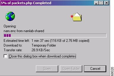
The Capture Download Window (Figure 6-2) is displayed.
Figure 6-2 Capture Download Window
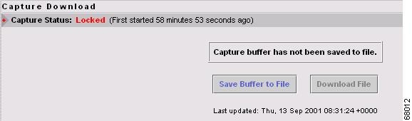
The Capture Status line displays the status of the current capture.
A display area in the main window shows whether the capture buffer has already been saved to a file.
•If the capture buffer has not been saved, the following message is displayed:
Capture buffer has not been saved to file.•If the capture buffer has been saved, a message similar to the following is displayed:
Capture buffer saved to file on Thu, 9 Aug 2001 00:00:00 +0000.File Size: bytes PacketsSaved in File: 246085Packets in Buffer Now: 69511Step 3 Do one of the following:
Note You must save the capture buffer to a file before you can download it.
•To save the buffer to a file, click Save Buffer to File. The Capture Download Window—Saving Capture Buffer Window (Figure 6-3) is displayed:
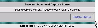
Figure 6-3 Capture Download Window—Saving Capture Buffer Window
Tip To refresh the information after a few moments, click Update Status.
•To download the file to your desktop, click Download File, then go to Step 4.
The Capture Download Window shows the status after the capture buffer has been successfully saved.
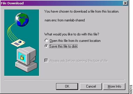
Step 4 If you clicked Download File, the File Download Dialog Box (Figure 6-4) is displayed. Do one of the following:
•To open the file on your desktop, select Open this file from its current location.
•To save the file to your hard drive, select Save this file to disk, then enter a destination file location and name in the File Download Dialog Box (Figure 6-4).
Figure 6-4 File Download Dialog Box
In both cases. the File Transfer Dialog Box (Figure 6-5) shows:
•The estimated amount of time before the file opens on your desktop or is written to your hard drive.
•The location to which the file is being transferred (a temporary folder to open on your desktop or the output filename you specified).
•The file transfer rate in KB/sec.
Figure 6-5 File Transfer Dialog Box
Setting Up Custom Capture Filters
You can use custom capture filters to create and save specialized filters to disregard everything except the information you are interested in when you capture data.
For more information about using custom filters when capturing data, see the "Capturing Using a Custom Filter" section.
See these topics for help setting up and managing custom capture filters:
•Creating Custom Capture Filters.
•Editing Custom Capture Filters.
•Deleting Custom Capture Filters.
Creating Custom Capture Filters
Step 1 Click the Capture tab.
Step 2 Click Custom Filters.
The Custom Capture Filters dialog box is displayed.
Step 3 Click Create.
The Custom Capture Filter Dialog Box (Table 6-4) is displayed.
Step 4 Enter information in each of the fields as appropriate.
Step 5 Do one of the following:
•To create the filter, click Apply.
•To cancel the changes, click Reset.
Tips for Creating Custom Capture Filter Expressions
•The TOS value is stored in byte 1 (the second byte) in the IP header. To match the IP packet with a TOS value of 16 (0x10), enter:
Data—10
Offset—1
Base—IP•The source address of an IP packet is stored in bytes 12 to 15 in the IP header. To match IP packets with a source address of 15.16.17.18, enter:
Data—0f 10 11 12
Offset—12
Base—IP•To match IP packets with a source address of 15.*.*.18 (where * is any number from 0 to 255), enter:
Data—0f 00 00 12
Data Mask—ff 00 00 ff
Offset—12
Base—IP•To match IP packets with a source address of 15.16.17.18 and a destination address different than 15.16.17.19, enter:
Data—f0 10 12 12 0f 10 11 13
Data Mask—ff ff ff ff ff ff ff ff
Data Not Mask—00 00 00 00 00 00 00 00
Offset—12
Base—IPEditing Custom Capture Filters
Step 1 Click the Capture tab.
Step 2 Click Custom Filters.
The Custom Capture Filters dialog box is displayed.
Step 3 Select the filter to edit, then click Edit.
The Custom Capture Filter dialog box (see Table 6-4) is displayed.
Step 4 Enter information in each of the fields as appropriate.
Step 5 Do one of the following:
•To apply the changes, click Apply.
•To cancel the changes, click Reset.
Deleting Custom Capture Filters
Step 1 Click the Capture tab.
Step 2 Click Custom Filters.
The Custom Capture Filters dialog box is displayed.
Step 3 Select the filter to delete, then click Delete.
Step 4 In the confirmation dialog box, do one of the following:
•To delete the filter, click OK.
•To cancel, click Cancel.
Setting Up Custom Decode Filters
Use custom decode filters to create and save customized filters to use in the Decode window to limit which packets are to be displayed.
See these topics for help setting up and managing custom decode filters:
•Creating Custom Decode Filters.
•Editing Custom Decode Filters.
•Deleting Custom Decode Filters.
Creating Custom Decode Filters
Step 1 Click the Capture tab.
Step 2 Click Custom Filters.
Step 3 In the contents, click Decode Filters.
The Custom Decode Filters dialog box is displayed.
Step 4 Click Create.
The Custom Decode Filter Dialog Box (Table 6-5) is displayed.
Step 5 Enter information in each of the fields as appropriate.
Table 6-5 Custom Decode Filter Dialog Box
Field Description Usage NotesFilter Name
The name of the capture filter.
Enter the name of the filter to be created.
Description
The description of the capture filter.
Enter a description of the filter.
Protocol
The protocol to match with the packet.
Select a protocol from the list. (Select All to match all packets regardless of protocol.)
Address
(MAC or IP)Indicates whether to filter by MAC or IP address.
•Select MAC to filter using the source/destination MAC address of the packets.
•Select IP to filter using the source/destination addresses of the packets.
Both Directions
Indicates whether the filter is applied to traffic in both directions.
•If the source is host A and the destination is host B, enabling both directions filters packets from A to B and B to A.
•If the source is host A and the destination is not specified, enabling both directions filters packets both to and from host A.
Source
Source address of the packets.
•For IP address, enter n.n.n.n, where n is 0 to 255 or n.n.n.n/s where s is the subnet mask
(0 to 32).•For MAC address, enter hh hh hh ..., where hh are hexadecimal numbers from 0 to 9 or a to f.
Destination
Destination address of the packets.
•For IP address, enter n.n.n.n, where n is 0 to 255 or n.n.n.n/s where s is the subnet mask
(0 to 32).•For MAC address, enter
hh hh hh hh hh hh, where hh are hexadecimal numbers from
0-9 or a-f.Offset
The offset (in bytes) from the Base where packet data-matching begins.
Enter a decimal number.
Base
The base from which the offset is calculated.
•If you select absolute, the offset is calculated from the absolute beginning of the packet (for example, the beginning of the Ethernet frame).
•If you select protocol, the offset is calculated from the beginning of the protocol portion of the packet. If the packet does not contain the protocol, the packet fails this match.
Select absolute or a protocol.
Data Pattern
The data to be matched with the packet.
Enter hh hh hh ..., where hh are hexadecimal numbers from 0-9 or a-f.
Leave blank if not applicable.
Filter Expression
An advanced feature to set up complex filter conditions.
The simplest filter allows you to check for the existence of a protocol or field. For example, to see all packets that contain the IPX protocol, you can use the simple filter expression ipx.
See the "Tips for Creating Custom Decode Filter Expressions" section.
Step 6 Do one of the following:
•To create the filter, click Apply.
•To cancel the changes, click Reset.
Tips for Creating Custom Decode Filter Expressions
•You can construct custom decode filter expressions using the following logical and comparison operators:
and
Logical AND
or
Logical OR
xor
Logical XOR
not
Logical NOT
==
Equal
!=
Not equal
>
Greater than
<
Less than
>=
Greater than or equal to
<=
Less than or equal to
•You can also group subexpressions within parentheses.
•You can use the following fields in filter expressions:
Examples of Custom Decode Filter Expressions
•To match SNMP packets from 111.122.133.144, enter:
snmp and (ip.src == 111.122.133.144)•To match IP packets from the 111.122 Class B network, enter:
ip.addr == 111.122.0.0/16•To match TCP packets to and from port 80, enter:
tcp.port == 80•The TOS value is stored in byte 1 (the second byte) in the IP header. To match the IP packet with the TOS value 16 (0x10), enter:
ip[1:1] == 10•The TCP acknowledgement number is stored in bytes 8 through 11 in the TCP header. To match the TCP packet with acknowledgement number 12345678 (0xBC614E), enter:
tcp[8:4] == 00:BC:61:4E
Note You can use a filter expression with other fields in the Custom Decode Filter dialog box. In this case, the filter expression is ANDed with other conditions.
Invalid or conflicting filter expressions result in no packet match.
Editing Custom Decode Filters
Step 1 Click the Capture tab.
Step 2 Click Custom Filters.
Step 3 In the contents, click Decode Filters.
The Custom Decode Filters dialog box is displayed.
Step 4 Select the filter to edit, then click Edit.
Step 5 Change the information in each of the fields as appropriate.
Step 6 Do one of the following:
•To apply the changes, click Apply.
•To cancel the changes, click Reset.
Deleting Custom Decode Filters
Step 1 Click the Capture tab.
Step 2 Click Custom Filters.
Step 3 In the contents, click Decode Filters.
The Custom Decode Filters dialog box is displayed.
Step 4 Select the filter to delete, then click Delete.
Step 5 In the confirmation dialog box, do one of the following:
•To delete the filter, click OK.
•To cancel, click Cancel.