- Preface
-
- Introducing the Cisco SNS 3415 and Cisco SNS 3495 Hardware Appliances
- Preparing to Install the Cisco SNS 3415 and Cisco SNS 3495 Hardware Appliances
- Installing the Cisco SNS 3415 and Cisco SNS 3495 Hardware Appliances
- Installing and Configuring Cisco Secure Access Control System with Cisco SNS 3415 and Cisco SNS 3495 Appliances
-
- Introducing the Cisco SNS 3515 and Cisco SNS 3595 Hardware Appliances
- Preparing to Install the Cisco SNS 3515 and Cisco SNS 3595 Hardware Appliances
- Installing the Cisco SNS 3515 and Cisco SNS 3595 Hardware Appliances
- Installing and Configuring Cisco Secure Access Control System with Cisco SNS 3515 and Cisco SNS 3595 Appliances
Installation and Upgrade Guide for Cisco Secure Access Control System 5.8.1
Bias-Free Language
The documentation set for this product strives to use bias-free language. For the purposes of this documentation set, bias-free is defined as language that does not imply discrimination based on age, disability, gender, racial identity, ethnic identity, sexual orientation, socioeconomic status, and intersectionality. Exceptions may be present in the documentation due to language that is hardcoded in the user interfaces of the product software, language used based on RFP documentation, or language that is used by a referenced third-party product. Learn more about how Cisco is using Inclusive Language.
- Updated:
- March 22, 2016
Chapter: Introducing the Cisco SNS 3515 and Cisco SNS 3595 Hardware Appliances
Introducing the Cisco SNS-3515 and Cisco SNS-3595 Hardware Appliances
This chapter gives an overview of the Cisco Secure Access Control System (Cisco SNS-3515 and Cisco SNS-3595) hardware. It covers the appliance hardware, major components, controls, connectors, and front- and rear-panel LED indicators.
■![]() LED Indicators on Cisco SNS 3515 and 3595 Appliances
LED Indicators on Cisco SNS 3515 and 3595 Appliances
Product Overview
This section describes the power requirements, rack-mount hardware kit, and features of the Cisco SNS-3515 and Cisco SNS-3595 appliances.
■![]() Cisco SNS-3515 and Cisco SNS-3595 Appliances Overview
Cisco SNS-3515 and Cisco SNS-3595 Appliances Overview
■![]() Cisco SNS-3515 and Cisco SNS-3595 Appliances Hardware Specifications
Cisco SNS-3515 and Cisco SNS-3595 Appliances Hardware Specifications
■![]() Product Serial Number Location
Product Serial Number Location
■![]() Cisco Product Identification Tool
Cisco Product Identification Tool
Cisco SNS-3515 and Cisco SNS-3595 Appliances Overview
The Cisco SNS-3515 or 3595 server is designed for performance and density over a wide range of business workloads, from web serving to distributed databases.
Building on the success of the Cisco SNS-3515 or 3595 server, the enterprise-class Cisco SNS-3515 or 3595 server further extends the capabilities of the Cisco Unified Computing System portfolio in a 1U form factor. The Cisco SNS-3515 server does this with the addition of the Intel Xeon processor E5-2600 product family, which delivers significant performance and efficiency gains. In addition, the Cisco SNS-3515/3595 server offers up to 64GB of RAM, 8 drives, and 2 x 1 GbE lights-out management (LOM) ports that deliver outstanding levels of density and performance in a compact package.
Cisco SNS-3515 and Cisco SNS-3595 Appliances Hardware Specifications
Table 1describes the hardware specifications of Cisco SNS-3515 and Cisco SNS-3595 appliances.
|
|
|
|
|---|---|---|
| ■ ■ |
||
| ■ ■ |
Note: ACS 5.8.1 supports an optional redundant power supply unit for Cisco SNS-3515-ACS-K9.
Chasis Front View
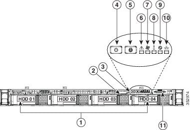
Figure 1 shows the Cisco SNS-3515 appliance.
Figure 1 Cisco SNS-3595/3515 Appliance Front View
|
|
|
||
KVM connector (used with KVM cable that provides two USB 2.0, one VGA, and one serial connector) |
|||
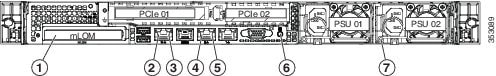
Chasis Rear View
Figure 2 shows the external features of the Cisco SNS-3515 and Cisco SNS-3595 appliances rear panel.
Figure 2 Cisco SNS-3515 or 3595 Appliance Rear View

|
|
|||
Product Serial Number Location
The serial number label is located at the top of the server near the front panel of the Cisco SNS-3515 or Cisco SNS-3595 appliance, shows the location of this label.
Cisco Product Identification Tool
The Cisco Product Identification (CPI) tool helps you retrieve the serial number of your Cisco products.
Before you submit a request for service online or by phone, use the CPI tool to locate your product serial number. You can access this tool from the Cisco Support website.
1.![]() Click the Get Tools & Resources link.
Click the Get Tools & Resources link.
2.![]() Click the All Tools (A-Z) tab.
Click the All Tools (A-Z) tab.
3.![]() Select Cisco Product Identification Tool from the alphabetical drop-down list.
Select Cisco Product Identification Tool from the alphabetical drop-down list.
This tool offers three search options:
■![]() Search by product ID or model name.
Search by product ID or model name.
■![]() Copy and paste the output of the show command to identify the product.
Copy and paste the output of the show command to identify the product.
Search results show an illustration of your product with the serial number label location highlighted. Locate the serial number label on your product and record the information before you place a service call.
You can access the CPI tool at:
http://tools.cisco.com/Support/CPI/index.do
To access the CPI tool, you require a Cisco.com user ID and password. If you have a valid service contract but do not have a user ID or password, you can register at:
Replaceable Component Locations
This section shows the locations of the field-replaceable components. The view in Figure 1-4 is from the top down with the top cover and air baffle removed.
Figure 3 Replaceable Component Locations

LED Indicators on Cisco SNS 3515 and 3595 Appliances
This section describes the front- and rear-panel controls, ports, and LED indicators on the Cisco SNS-3515 or Cisco SNS-3595 appliances.
■![]() Cisco SNS-3515 or 3595 Appliance Front-Panel View
Cisco SNS-3515 or 3595 Appliance Front-Panel View
■![]() Cisco SNS-3515 or 3595 Appliance Back-Panel View
Cisco SNS-3515 or 3595 Appliance Back-Panel View
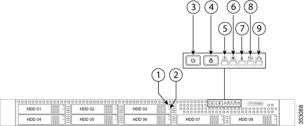
Cisco SNS-3515 or 3595 Appliance Front-Panel View
Figure 4 shows the components of the Cisco SNS-3515 or Cisco SNS-3595 appliance front-panel view.
|
|
|||
Table 2 describes the LEDs located on the front panel of the Cisco SNS-3515 or Cisco SNS-3595 appliance
|
|
|
|---|---|
| Note: If your controller is a Cisco UCS RAID SAS 9300-8i or 9300-8e HBA, see Cisco UCS SAS 9300-8i and 9300-8e HBA Considerations for differing LED behavior. |
■ ■ ■ |
■ |
|
■ ■ ■ |
|
■ ■ ■ – – ■ |
|
■ ■ ■ |
|
■ ■ ■ |
|
■ ■ ■ |
|
■ ■ ■ |
Cisco SNS-3515 or 3595 Appliance Back-Panel View
Figure 2 shows the components of the Cisco SNS-3515 and Cisco 3595 appliance back-panel view.
|
|
Optional mLOM card LEDs (see Table 3) |
||
Table 3 describes the LEDs located on the front panel of the Cisco SNS-3515 or Cisco SNS-3595 appliance.
|
|
|
|---|---|
| ■ ■ ■ |
Internal Diagnostic LEDs
The server has internal fault LEDs for CPUs, DIMMs, fan modules, SD cards, the RTC battery, and the mLOM card. These LEDs are available only when the server is in standby power mode. An LED lights amber to indicate a faulty component.
Note: Power must be connected to the server for these LEDs to be operate.
Figure 6 shows the locations of these internal LEDs in Cisco SNS-3515 or Cisco SNS-3595 appliance.
Figure 6 Cisco SNS-3515 or 3595 Internal Diagnostic LED Locations
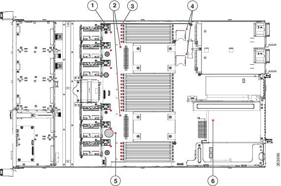
The following table describes the callouts in Figure 6
|
|
Fan module fault LEDs (one next to each fan connector on the motherboard) |
|
|
|
|
|
||
|
|
DIMM fault LEDs (one in front of each DIMM socket on the motherboard) |
|
Table 4 describes the internal diagnostic LEDs located inside the Cisco SNS-3515 or Cisco SNS-3595 appliance.
|
|
|
|---|---|
Regulatory Compliance
For regulatory compliance and safety information, see Regulatory Compliance and Safety Information for Cisco Secure Access Control System.
For more information, see Obtain Documentation and Submit a Service Request.
 Feedback