- Preface
- Installation Roadmap
- Overview
- Installing the Power Enclosure, Power Trays, and Exterior Cosmetics
- Installing the Power Components
- Installing the Shelf Controller Cards and Fabric Cards
- Removing and Replacing Chassis Components
- System Specifications
- System Product IDs
- Cabling a Multi-Chassis Configuration
Cisco Network Convergence System 6000 Fabric Card Chassis Hardware Installation Guide
Bias-Free Language
The documentation set for this product strives to use bias-free language. For the purposes of this documentation set, bias-free is defined as language that does not imply discrimination based on age, disability, gender, racial identity, ethnic identity, sexual orientation, socioeconomic status, and intersectionality. Exceptions may be present in the documentation due to language that is hardcoded in the user interfaces of the product software, language used based on RFP documentation, or language that is used by a referenced third-party product. Learn more about how Cisco is using Inclusive Language.
- Updated:
- October 25, 2016
Chapter: Installing the Power Enclosure, Power Trays, and Exterior Cosmetics
Installing the Power Enclosure, Power Trays, and Exterior Cosmetics
This chapter provides instructions on installing the Cisco NCS 6000 Fabric Card Chassis power enclosure, power trays, and exterior cosmetics.
About the Power Enclosure
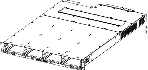
The Cisco NCS 6000 FCC ships with a separate empty power enclosure (Cisco PID NCS-F-PWR-SHELF). The power enclosure consists of one power shelf, four slots for AC or DC power trays, and two power control modules (PCMs).
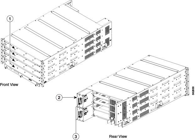
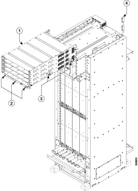
The upper two power trays (PT0 and PT1) are referred to as power shelf 0 (PS0), and the lower two power trays (PT2 and PT3) are referred to as power shelf 1 (PS1) Figure 3. Each set of power trays has a power control module (PCM) with its own I/O power switch. Three AC power modules or four DC power modules can be installed in each power tray. See the Installing an AC or DC Power Module section.
 Note | Usually, it is not necessary to remove the power enclosure although it is field-serviceable. For information about removing the power enclosure components, see the Replacing an AC or DC Power Tray section. |
|
1 |
Four power tray slots for AC or DC power trays |
3 |
PCM I/O power switches (one per PCM) |
|
2 |
Two PCMs |
Installing the Power Enclosure
This section describes how to install the power enclosure in the Cisco NCS 6000 FCC.
Required Tools and Equipment
-
6-inch, Number-2 Phillips screwdriver
-
Power enclosure (Cisco PID NCS-F-PWR-SHELF)
Note | The power enclosure weighs approximately 30 pounds and sits on top of the FCC. To prevent injury, we recommend that you use a ladder and use two people when installing the power shelf. |
Steps
Follow these steps to attach the power enclosure to the FCC:
Installing the Power Trays
This section describes how to install an AC or DC power tray in the power enclosure and includes the following topics:
Note | Although there are differences between AC and DC power trays, they are installed by using the same procedures described in this section. Once they are installed into an FCC that is properly grounded, external grounding to the power tray is not needed. |
About the AC and DC Power Trays
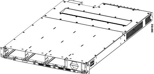
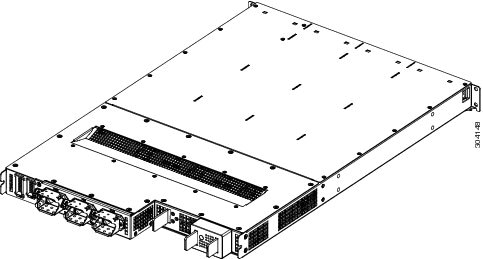
The Cisco NCS 6000 FCC power enclosure supports either four AC power trays or four DC power trays. An AC power tray houses up to three AC power modules, while a DC power tray houses up to four DC power modules. See the Installing an AC or DC Power Module section.
Note | Only one type of power tray can be installed in the power enclosure. You cannot mix AC and DC power trays. |
Note | For a DC power tray, the rear input LED starts to light up when the input voltage reaches -20 VDC, gets brighter as the voltage increases, and is fully lit when the input voltage reaches -48 VDC. |
Installing an AC or DC Power Tray
This section describes how to install an AC or DC power tray in the Cisco NCS 6000 FCC.
Note | For information about removing a power tray, see the Replacing an AC or DC Power Tray section. |
Prerequisites
Before you install an AC or DC power tray, do the following:
- Remove the top grilles from both the front and rear sides of the FCC, if installed.
- Ensure the power tray you are about to install is empty. Do not install a power tray into the FCC with the PMs installed in the power tray.
Required Tools and Equipment
-
Four M4 x 10 mm screws per power tray
-
6-inch, Number-2 Phillips screwdriver
-
Number-2 Phillips torque screwdriver with torque rated up to 55 in-lb (6.2 N-m)
-
AC or DC power tray
-
AC power tray (Cisco PID NCS-AC-PWRTRAY)
-
DC power tray (Cisco PID NCS-DC-PWRTRAY)
-
Steps
To install an AC or DC power tray, follow these steps:
| Step 1 | Using two
people, one to support the power tray underneath and the other to keep it
steady, lift the power tray up and slide it partially into a power tray slot on
the power enclosure.
| ||
| Step 2 | Grasping both
handles simultaneously, push both the left and right handles in at the same
time to push the tray into the power enclosure. Slide the tray all the way into
the enclosure until both power tray handles engage the slots.
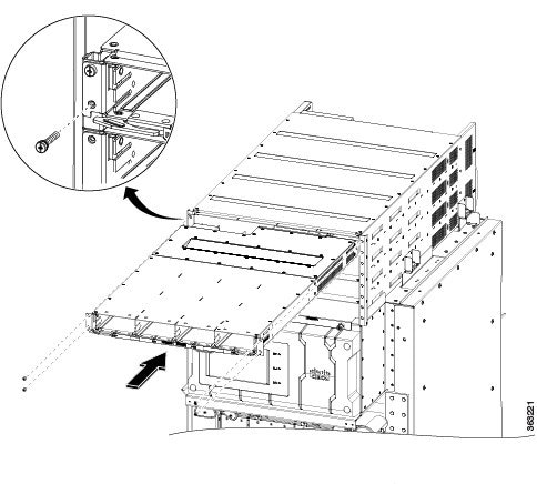 | ||
| Step 3 | Use the screwdriver to loosely tighten the four M4 x 10 mm screws that attach the power tray to the power enclosure. | ||
| Step 4 | Use the torque
screwdriver to tighten the four screws to a torque value of 15 in-lb (1.69 N-m)
to 20 in-lb (2.26 N-m).
|
Installing the Exterior Cosmetics
This section describes how to install the exterior cosmetics on the Cisco NCS 6000 FCC and includes the following topics:
For information about removing the external cosmetics, see the Removing the Exterior Cosmetics section.
- Overview of the Exterior Cosmetics
- Installing the Front Exterior Cosmetics
- Installing the Rear Exterior Cosmetics
Overview of the Exterior Cosmetics
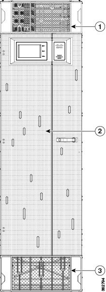
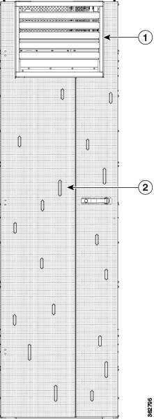
The Cisco NCS 6000 FCC is shipped with exterior cosmetics for the front side and rear side of the FCC.
|
1 |
Top grille |
3 |
Bottom grille |
|
2 |
Front door |
|
|
|
1 |
Rear exhaust air deflector |
|
2 |
Rear door |
Installing the Front Exterior Cosmetics
This section describes how to install the front side exterior cosmetics on the Cisco NCS 6000 FCC. We recommend that you install the exterior cosmetics in the order outlined in this section.
Note | Before performing these tasks, you must first unpack and secure the chassis. See the Cisco Network Convergence System 6000 Series Routers Unpacking, Moving, and Securing Guide. |
Prerequisites
Required Tools and Equipment
-
8-inch, Number-1 Phillips screwdriver (magnetic head preferable)
-
Two vertical cable troughs (left and right troughs are interchangeable)
-
Three door hinges
-
Three door latches
-
Four trough retention brackets
-
Front door
-
Door grounding cable
-
Craft panel cover
-
Front top grille
-
Front bottom grille
For information on the cosmetic PID numbers, see Cosmetic Product IDs.
Steps
To install the front exterior cosmetics, follow these steps:
| Step 1 | Remove the upper and lower horizontal cable management brackets (preinstalled on the FCC) by loosening and removing the eight pan-head screws (four per bracket). One bracket is located above the upper card cage and the other bracket is below the lower card cage. | ||||||||||||||
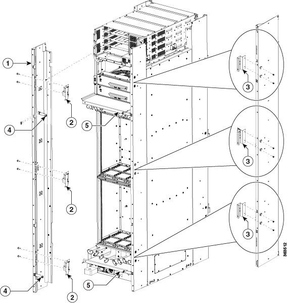
| Step 2 | Attach the left
and right vertical cable troughs to the front of the FCC. The two vertical
cable troughs are installed inverted from each other. Each trough is marked
FRONT to ensure that you install the trough on the correct side of the FCC.
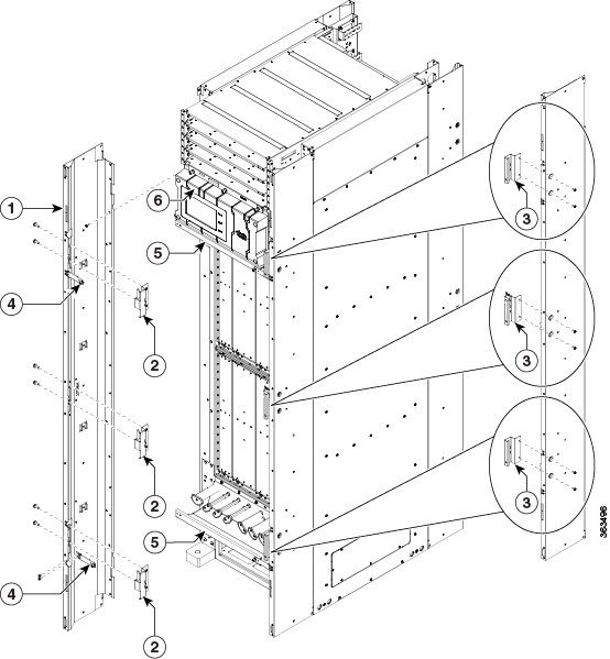
For each vertical cable trough
| ||||||||||||||
| Step 3 | Reattach the upper and lower horizontal cable management brackets by inserting and tightening the eight pan-head screws (four per bracket). | ||||||||||||||
| Step 4 | Attach the three door hinges and the three door latches by using two pan-head screws each. | ||||||||||||||
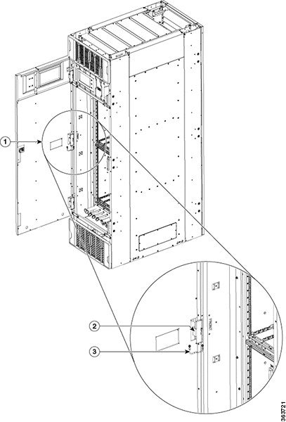
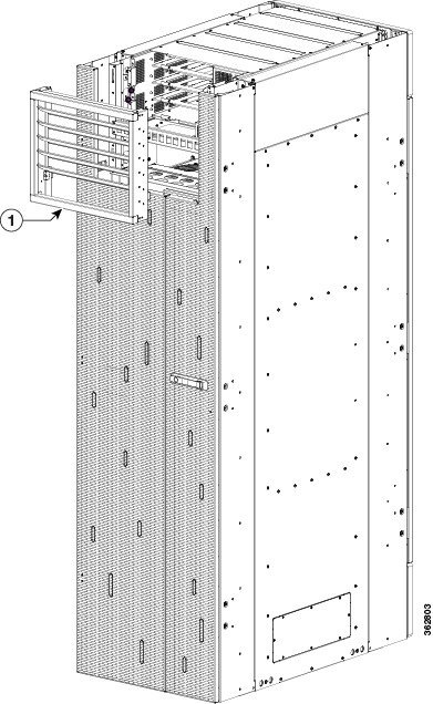
| Step 5 | Align the front
door (see the following figure) with the three door hinges on the FCC. The door
will then drop into position onto the hinge attachment pins.
| ||||||||||||||
| Step 6 | Attach the grounding cable to the front door. | ||||||||||||||
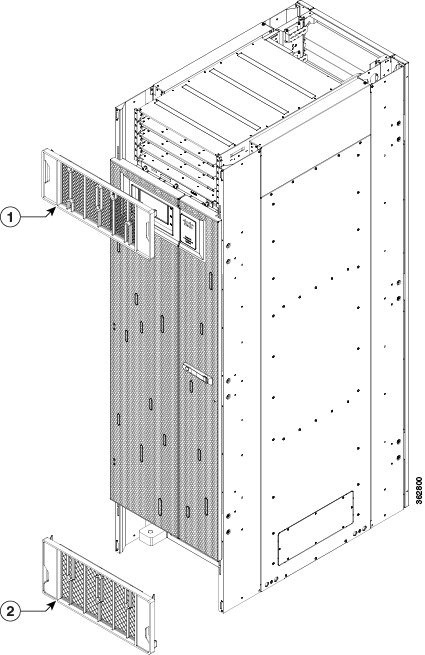
| Step 7 | Attach the grilles to the troughs (see the following figure). |
Installing the Rear Exterior Cosmetics
This section describes how to install the rear side exterior cosmetics on the Cisco NCS 6000 FCC. We recommend that you install the exterior cosmetic components in the order outlined in this section.
Prerequisites
Required Tools and Equipment
-
8-inch, Number-1 Phillips screwdriver (magnetic head preferable)
-
Two vertical cable troughs (left and right are interchangeable)
-
Three door hinges
-
Three door latches
-
Four trough retention brackets
-
Exhaust plenum bracket
-
Rear door
-
Door grounding cable
-
Rear exhaust air deflector
Steps
To install the rear exterior cosmetics, follow these steps:
| Step 1 | Remove the upper and lower horizontal cable management brackets (preinstalled on the FCC) by loosening and removing the eight pan-head screws (four per bracket). One bracket is located above the upper card cage and the other bracket is below the lower card cage. | ||||||||||||||
| Step 2 | Attach the left
and right vertical cable troughs to the rear of the FCC. The two vertical cable
troughs are inverted from each other. Each trough is marked REAR to ensure that
you install the trough on the correct side of the FCC.
For each vertical cable trough:
| ||||||||||||||
| Step 3 | Reattach the upper and lower horizontal cable management brackets by inserting and tightening the eight pan-head screws (four per bracket). | ||||||||||||||
| Step 4 | Attach the side
filler panels.
For each filler panel: | ||||||||||||||
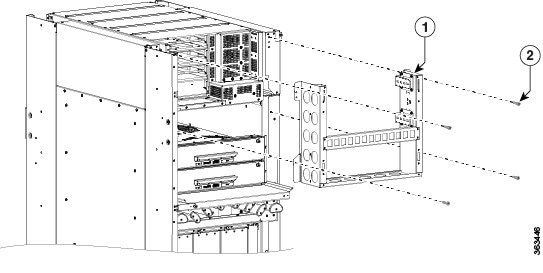
| Step 5 | Attach the exhaust plenum bracket to the FCC (cutouts facing up) using six pan-head screws, three screws each side. Before installing the bracket, remove the topmost screw on each of the vertical troughs. | ||||||||||||||
| Step 6 | Tighten the two
8-32 screws on the filler panel (that you previously installed) securely to the
FCC.
| ||||||||||||||
| Step 7 | Attach the three door hinges and the three door latches by using two pan-head screws each (Figure 13). | ||||||||||||||
| Step 8 | Align the
rear door with the three door hinges on the FCC (Figure
11). The door will then drop into position onto the hinge attachment
pins.
| ||||||||||||||
| Step 9 | Attach the
grounding cable to the rear door (step 7).
| ||||||||||||||
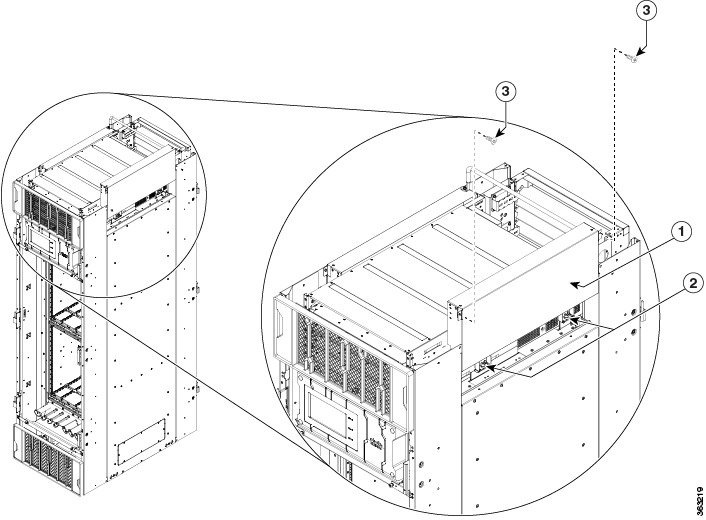
| Step 10 | Attach the
exhaust air deflector by carefully inserting its mounting tabs into the exhaust
plenum brackets. Press the deflector firmly against the vertical cable troughs
until it snaps on.
|
 Feedback