Modular QoS Configuration Guide for Cisco NCS 5500 Series Routers, IOS XR Release 7.3.x
Bias-Free Language
The documentation set for this product strives to use bias-free language. For the purposes of this documentation set, bias-free is defined as language that does not imply discrimination based on age, disability, gender, racial identity, ethnic identity, sexual orientation, socioeconomic status, and intersectionality. Exceptions may be present in the documentation due to language that is hardcoded in the user interfaces of the product software, language used based on RFP documentation, or language that is used by a referenced third-party product. Learn more about how Cisco is using Inclusive Language.
Congestion management
features allow you to control congestion by determining the order in which a
traffic flow (or packets) is sent out an interface based on priorities assigned
to packets. Congestion management entails the creation of queues, assignment of
packets to those queues based on the classification of the packet, and
scheduling of the packets in a queue for transmission.
Note
From Cisco IOS XR Release 7.3.1 onwards, systems with Cisco NC57 line cards running in compatibility mode support QoS over Layer 2 services for:
Local switching [xconnect or bridging]
L2 VPN – VPWS
The types of traffic regulation mechanisms supported are:
The ingress traffic management model relies on packet queueing on the egress interface using Virtual Output Queueing (VOQ)
on the ingress. In this model, buffering takes place at ingress. Here’s how the VOQ process works.
Your routers support up to eight output queues per main interface or physical port. For every egress output queue, the VOQ
model earmarks buffer space on every ingress pipeline. This buffer space is in the form of dedicated VOQs. These queues are
called virtual because the queues physically exist on the ingress interface only when the line card actually has packets enqueued
to it. To support the modular model of packet distribution, each network processing unit (NPU) core at the ingress needs connectors
to every egress main interface and subinterface. The ingress traffic management model thus requires a mesh of connectors to
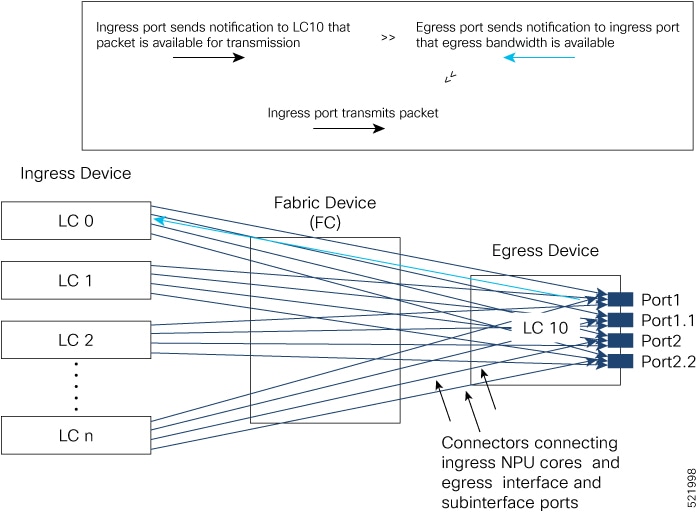
connect the ingress NPU cores to the egress interfaces, as shown in The Ingress Traffic Management Model.
Figure 1. The Ingress Traffic Management Model
In the figure, every ingress interface (LC 0 through LC n) port has eight VOQs for the single egress line card LC 10.
Here’s how packet transmission takes place:
When a packet arrives at ingress port (say on LC 0), the forwarding lookup on ingress line card points to the egress interface.
Based on the egress interface (say it is on LC10), the packet is enqueued to the VOQ of LC 10. The egress interface is always
mapped to a physical port.
Once egress bandwidth is available, the LC 10 ports ready to receive the packets (based on the packet marking and distribution
model) send grants to the ingress ports via the connectors. (The figure shows a separate line for the grant for the sake of
visual representation. In reality, the same connector is used for requests, grants, and transmission between an NPU core at
the ingress and the egress port on LC 10.)
The ingress ports respond to this permission by transmitting the packets via FC to the LC 10 ports. (The time it takes for
the ingress ports to request for egress port access, the egress port to grant access, and the packet to travel across FC is
the round-trip time.)
The VOQ model thus operates on the principle of storing excess packets in buffers at ingress until bandwidth becomes available.
Based on the congestion that builds up and the configured threshold values, packets begin to drop at the ingress itself, instead
of having to travel all the way to the egress interface and then getting dropped.
Class-based Weighted
Fair Queueing
Class-based Weighted Fair Queueing
(CBWFQ) allows definition of traffic classes based on customer match criteria.
With CBWFQ you can define traffic classes and assign guaranteed amount of
minimum bandwidth to them. CBWFQ also allows for a strict priority queue for
delay-sensitive traffic.
Bandwidth
Remaining
The CBWFQ algorithm derives the weight for each class from the bandwidth remaining value allocated to the class. The bandwidth remaining option specifies a weight for the class to the
CBWFQ . After the priority-queue is serviced, the leftover bandwidth is distributed as per bandwidth remaining ratio (BWRR) or percentage.
If you do not configure this command for any class, the default value of the BWRR is considered as 1 (one). In the case of
bandwidth remaining percent, the remaining bandwidth is equally distributed among other classes, to make it 100 percentage (100%).
Restrictions
The
bandwidth
remaining command is supported only for egress policies.
Configure
Minimum Bandwidth and
Bandwidth Remaining
Guidelines
The bandwidth, bandwidth remaining, shaping, queue-limit, and random-detect commands may be configured together in the same class. The priority command cannot be configured along with bandwidth, bandwidth remaining commands, but can be configured with shaping, queue-limit and random-detect commands in the same class.
Configuration
Example
You have to
accomplish the following to complete the
minimum bandwidth and
bandwidth remaining configuration:
Creating or
modifying a policy-map that can be attached to one or more interfaces
Specifying the
traffic class whose policy has to be created or changed
Allocating the
minimum bandwidth and
leftover bandwidth for the class
Low-Latency Queueing
with Strict Priority Queueing
The Low-Latency Queueing (LLQ) feature brings strict priority queuing (PQ) to the CBWFQ scheduling mechanism. Priority Queueing (PQ) in strict priority mode ensures that one type of traffic is sent, possibly at the expense of all others.
For PQ, a low-priority queue can be detrimentally affected, and, in the worst case, never allowed to send its packets if a
limited amount of bandwidth is available or the transmission rate of critical traffic is high.
Configure Low
Latency Queueing with Strict Priority Queueing
Configuring low
latency queueing (LLQ) with strict priority queuing (PQ) allows delay-sensitive
data such as voice to be de-queued and sent before the packets in other queues
are de-queued.
Guidelines
Only priority level 1 to 7 is supported, with 1 being the highest priority and 7 being the lowest. However, the default CoSQ 0 has the lowest priority among all.
Priority level 1 to 7 is supported for non-H-QoS profiles, with 1 being the highest priority and 7 being the lowest. For H-QoS
profiles, priority level 1 to 4 is supported. For all profiles, however, the class default is CoSQ 0 and has the lowest priority
among all.
Egress policing is not supported. Hence, in the case of strict priority queuing, there are chances that the other queues do
not get serviced.
You can configure shape average and queue-limit commands along with priority.
A Priority Queue (PQ) can oversubscribe bandwidth when other queues do not utilize the entire port bandwidth. However, oversubscription
of traffic is supported only with a single priority level.
Configuration
Example
You have to
accomplish the following to complete the LLQ with strict priority queuing:
Creating or
modifying a policy-map that can be attached to one or more interfaces
Specifying the
traffic class whose policy has to be created or changed
Specifying
priority to the traffic class
(Optional) Shaping the traffic to a specific bit rate
Traffic shaping allows you to control the traffic flow exiting an interface to match its transmission to the speed of the
remote target interface and ensure that the traffic conforms to policies contracted for it. Traffic adhering to a particular
profile can be shaped to meet downstream requirements, hence eliminating bottlenecks in topologies with data-rate mismatches.
Note
If you apply a policy map that has configured traffic policing and traffic shaping on the basis of a percentage of bandwidth
available on the interface and you change the speed of the interface, you must delete that policy map and reattach it to the
interface. Else, QoS programming for the earlier speed remains in effect and does not change with change in the port speed.
Note
Traffic shaping is supported only in egress direction.
Configure Traffic
Shaping
The traffic shaping performed on outgoing interfaces is done at the Layer 1 level and includes the Layer 1 header in the rate
calculation.
Guidelines
Only egress traffic shaping is supported.
It is mandatory to configure all the eight traffic-class classes (including class-default) for the egress policies.
You can configure shape average command along with priority command.
Configuration Example
You have to accomplish the following to complete the traffic shaping configuration:
Creating or modifying a policy-map that can be attached to one or more interfaces
Specifying the traffic class whose policy has to be created or changed
Shaping the traffic to a specific bit rate and set peak burst size
class-map c5
 match traffic-class 5
commit

policy-map egress_policy1
 class c5
  shape average percent 50 1000
 !
 class class-default
 !
 end-policy-map
!

interface HundredGigE0/6/0/18
 service-policy output egress_policy1
!
Verification
Router#  ios#show qos interface tenGigE 0/0/0/0 output

Wed Jul 10 14:18:37.783 UTC
NOTE:- Configured values are displayed within parentheses
Interface TenGigE0/0/0/0 ifh 0x120  -- output policy
NPU Id:                        0
Total number of classes:       1
Interface Bandwidth:           10000000 kbps
Policy Name:                   test
VOQ Base:                      1024
Accounting Type:               Layer1 (Include Layer 1 encapsulation and above)
------------------------------------------------------------------------------
Level1 Class                             =   class-default
Egressq Queue ID                         =   1024 (Default LP queue)
Queue Max. BW.                           =   5031499 kbps (50 %)
Queue Min. BW.                           =   0 kbps (default)
Inverse Weight / Weight                  =   1 / (BWR not configured)
Guaranteed service rate                  =   5000000 kbps
Peak burst                               =   2240 bytes (1000 bytes)
TailDrop Threshold                       =   6258688 bytes / 10 ms (default)
Important Notes
From Cisco IOS XR Release 6.6.25 onwards, a shaper on a bundle interface also allows absolute rates apart from the already supported units of percentage,
per-thousand and per-million.
With this feature you can configure a desired traffic policy, to which your network complies, by using the bandwidth management
technique of two-level traffic shaping. You can also increase the Link Aggregation Group (LAG) sub-interface scale or pseudowires
up to 4K.
This increased scale value enables you to increase the number of devices connected to your router, resulting in benefits
such as increased bandwidth and cost-effective operations.
Your router supports two modes of egress traffic shaping:
The default non-Hierarchical QoS (H-QoS) mode, where the egress traffic shaping is configured only on main interfaces and no hierarchical policies are supported. In other
words, egress traffic shaping on subinterfaces isn’t supported in this mode.
The H-QoS mode, where egress traffic shaping is also supported on subinterfaces. This mode also supports hierarchical policies on the main
and subinterfaces.
Prior to Cisco IOS XR Release 7.3.1, the H-QoS mode restricted the scale of subinterfaces you could configure. For example, the maximum Link Aggregation Group
(LAG) subinterface scale or pseudowires is 1K in the H-QoS mode.
The enhancement described in this section, available from Cisco IOS XR Release 7.3.1 is applicable for the default non-H-QoS mode for egress QoS. It involves configuring two-level traffic shaper policy on the
main interface, while enabling you to increase the LAG subinterface scale or pseudowires to as much as 4K. What this means
is that you can also scale up the number of access devices you want to connect through LAG to your router, thus enabling:
Increased reliability and availability
Better use of physical resources
Increased bandwidth
Cost-effective operations
Restrictions and Guidelines
The following restrictions and guidelines apply while configuring two-level traffic shaper policy on the main interface in
(default) non-H-QoS mode:
The hierarchical egress policy support is only for main interfaces.
Subinterface behavior remains the same in non-H-QoS mode. No egress QoS support is available for subinterfaces.
This enhancement is applicable only for egress QoS, and there are no changes in ingress QoS behavior.
There’s no change to the current non-H-QoS flat policy behavior.
The minimum shaper rate varies between different ASICs.
Configure Two-Level Shaper Policy on Main Interface
To configure two-level shaper policy on main interface, you must:
Enter global configuration mode and create a two-level policy map.
Attach this policy map to the main interface.
/* Enter the global configuration mode and create the two-level policy map */
Router#configure
Router(config)# policy-map  two-level-pm
Router(config-pmap)#class class-default
Router(config-pmap-c)#shape average percent 20
Router(config-pmap-c)#service-policy child
Router(config-pmap-c)#root
Router(config)#policy-map child
Router(config-pmap)#class class-default
Router (config-pmap-c)#shape average percent 5
Router(config-pmap-c)#commit

/* Apply policy-map under interface */
Router(config)#interface hundredGigE 0/0/0/3
Router(config-intf)#service-policy output policy
Router(config-intf)#commit
Verify that the maximum bandwidth (shaping rate) for the parent policy (Level 1) is greater than the rate for the child policy
at Level 2.
Router#show qos interface hundredGigE 0/0/0/3 output
NOTE:- Configured values are displayed within parentheses
Interface HundredGigE0/0/0/3 ifh 0x68  -- output policy
NPU Id:                        0
Total number of classes:       2
Interface Bandwidth:           100000000 kbps
Policy Name:                  two-level-pm
SPI Id:                        0x0
VOQ Base:                      1048
Accounting Type:               Layer1 (Include Layer 1 encapsulation and above)
------------------------------------------------------------------------------
Level1 Class                             =   class-default
Queue Max. BW.                           =   20004211 kbps (20 %)
Queue Min. BW.                           =   20000305 kbps (default)
Inverse Weight / Weight                  =   1 / (BWR not configured)

   Level2 Class                             =   class-default
   Egressq Queue ID                         =   1048 (Default LP queue)
   Queue Max. BW.                           =   1000000 kbps (5 %)
   Queue Min. BW.                           =   0 kbps (default)
   Inverse Weight / Weight                  =   1 / (BWR not configured)
   Guaranteed service rate                  =   1000000 kbps
   Peak burst                               =   36864 bytes (default)
   TailDrop Threshold                       =   1249792 bytes / 10 ms (default)
   WRED not configured for this class
Traffic Policing
Traffic policing allows you to control the maximum rate of traffic sent or received on an interface and to partition a network
into multiple priority levels or class of service (CoS).Traffic policing manages the maximum rate of traffic through a token
bucket algorithm. The token bucket algorithm uses user-configured values to determine the maximum rate of traffic allowed
on an interface at a given moment in time. The token bucket algorithm is affected by all traffic entering or leaving the interface
(depending on where the traffic policy with traffic policing is configured) and is useful in managing network bandwidth in
cases where several large packets are sent in the same traffic stream. By default, the configured bandwidth value takes into
account the Layer 2 encapsulation that is applied to traffic leaving the interface.
Traffic policing also
provides a certain amount of bandwidth management by allowing you to set the
burst size (Bc) for the committed information rate (CIR). See,
Committed Bursts and Excess Bursts.
The router supports the following traffic policing mode(s):
Single-Rate Three-Color (SR3C) in color-blind mode.
Two-Rate Three-Color (2R3C) in color-blind mode. See Two-Rate Policer .
Note
In NC57-18DD-SE,QoS enhanced stats is enabled by default.
Restrictions
If you apply a policy map that has configured traffic policing and traffic shaping on the basis of a percentage of bandwidth
available on the interface and you change the speed of the interface, you must delete that policy map and reattach it to the
interface. Else, QoS programming for the earlier speed remains in effect and does not change with change in the port speed.
Traffic policing is supported only in ingress direction, and only color-blind mode is supported.
The policing rate accuracy may vary up to +/-2% from the configured policer value.
Policer marking is not supported.
Policers are configured in the interface at the core level and “show qos int <>” value is displayed at the NPU level.
For policers configured in a bundle interface where bundle members are from the same NPU but different cores (NPU cores),
each member sends the traffic up to the core level policer configuration, but “show qos int <>” displays the NPU level policer
output.
Example:
For bundle interface with two 10GE members (same NPU, but one interface from core0, one interface from core1) 2R3C policer
applied on bundle interface (1G confirm rate , 1G exceed rate – total 2G policer rate) will be shown on the “show qos int
<>” output):
For traffic in one out of two interfaces, the policed rate will be 1Gbps. For traffic on two interfaces, policed rate will
be 2Gbps.
Committed Bursts and Excess Bursts
Unlike a traffic shaper, a traffic policer does not buffer excess packets and transmit them later. Instead, the policer executes
a “send or do not send” policy without buffering. Policing uses normal or committed burst (bc) values and excess burst values (be) to ensure that the router reaches the configured committed information rate (CIR). Policing decides if a packet conforms
or exceeds the CIR based on the burst values you configure. Burst parameters are based on a generic buffering rule for routers,
which recommends that you configure buffering to be equal to the round-trip time bit-rate to accommodate the outstanding TCP
windows of all connections in times of congestion. During periods of congestion, proper configuration of the excess burst parameter enables the policer to drop packets less aggressively.
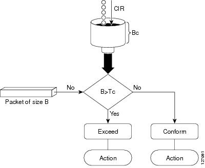
A single-rate
two-color (SR2C) policer provides one token bucket with two actions for each
packet: a conform action and an exceed action.
Figure 2. Workflow of
Single-Rate Two-Color Policer
Based on the committed information rate (CIR) value, the token bucket is updated at every refresh time interval. The Tc token
bucket can contain up to the Bc value, which can be a certain number of bytes or a period of time. If a packet of size B is
greater than the Tc token bucket, then the packet exceeds the CIR value and a default action is performed. If a packet of size B is less than the Tc token bucket, then the packet conforms and a different default action is performed.
Single-Rate Three-Color Policer
A single-rate three-color (SR3C) policer provides one token bucket with three actions for each packet: a conform action, an
exceed action and a violate action. The packet is marked based on the CIR value and the two associated burst size - committed
burst size (CBS) and excess burst size (EBS). If a packet does not exceed the CBS, it is marked as conformed packet. The packet
is marked as exceeded if it exceeds CBS, but not the EBS. If it exceeds the EBS as well, it is marked as violate packet.
Traffic policing is often configured on interfaces at the edge of a network to limit the rate of traffic entering or leaving
the network. The default conform action for single-rate two color policer is to transmit the packet and the default exceed
action is to drop the packet. Users cannot modify these default actions.
Configuration
Example
You have to
accomplish the following to complete the traffic policing configuration:
Creating or
modifying a policy-map that can be attached to one or more interfaces
Specifying the
traffic class whose policy has to be created or changed
The default conform action and exceed actions for single-rate three-color policer are to transmit the packet and the default
violate action is to drop the packet. User cannot modify these default actions.
Configuration
Example
You have to
accomplish the following to complete the traffic policing configuration:
Creating or
modifying a policy-map that can be attached to one or more interfaces
Specifying the
traffic class whose policy has to be created or changed
(Optional)
Specifying the marking action
Configuring the
policy rate for the traffic along with the peak-burst values
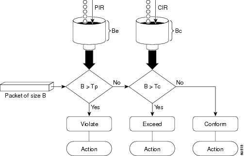
The two-rate policer manages
the maximum rate of traffic by using two token buckets: the committed token
bucket and the peak token bucket. The dual-token bucket algorithm uses
user-configured values to determine the maximum rate of traffic allowed on a
queue at a given moment. In this way, the two-rate policer can meter traffic at
two independent rates: the committed information rate (CIR) and the peak
information rate (PIR).
The dual-token bucket algorithm provides users with three actions for each packet—a conform action, an exceed action, and
an optional violate action. Traffic entering a queue with the two-rate policer configured is placed into one of these categories.
The actions are pre-determined for each category. The default conform and exceed actions are to transmit the packet, and the
default violate action is to drop the packet.
This figure shows how the
two-rate policer marks a packet and assigns a corresponding action to the
packet.
Figure 3. Marking Packets and Assigning
Actions—Two-Rate Policer
The router supports Two-Rate Three-Color (2R3C) policer.
Configure Traffic
Policing (Two-Rate Three-Color)
The default conform and exceed actions for two-rate three-color (2R3C) policer are to transmit the packet and the default
violate action is to drop the packet. Users cannot modify these default actions.
Configuration Example
You have to accomplish the following to complete the two-rate three-color traffic policing configuration:
Creating or modifying a policy-map that can be attached to one or more interfaces
Specifying the traffic class whose policy has to be created or changed
Shaper and policer rates can be configured in units of per-thousand and per-million on bundle interfaces. This provides the
ability to provision shape and police rates down to 100 kbps on bundle or link aggregation (LAG) interfaces even with 100
GE bundle members.
For example, consider a 100GE interface and simple policy.
Interface HundredGig0/0/0/0
Service-policy output TEST
Policy-map TEST
Class C
 Shape average per-thousand 5
End-policy
Per thousand represents 0.1% of the link bandwidth and per million represents 0.0001% of the link bandwidth.
Which means that for a 100G link, 5 parts per thousand is 0.5% of the link bandwidth. Hence, the shape average per thousand
of 5 in the above example enforces a shaper of 500 Mbps.
Shared Policer
The classification of the incoming packet occurs only once. However, based on the
different classification criteria, the shared policer feature allows sharing of the
policer bucket amongst two or more classes in a QoS policy map . That is, the same token
bucket is used for a traffic flow matching against any of the classes sharing the
policer.
For example, let us say a policer of 10 Mbps is shared among two classes C1 and C2. This
feature ensures that both C1 and C2 get traffic flow assigned on First Come First Serve
(FCFS) basis. Also that, if C2 does not have any traffic, C1 uses all of the 10 Mbps for
transmission.
This feature includes two components:
Policer Bucket Shared
Policer Bucket Referred
Policer Bucket Shared
The policer bucket shared feature defines and shares a policer bucket instance among
multiple classes.
Here is a sample configuration that defines and shares policer bucket instance sp1
:
In this configuration, a policy-map for class long-distance traffic type is created to
police at 1Mbps rate and the policer bucket is shared.
Policer Bucket Referred
The policer bucket referred feature refers a defined policer bucket instance. Shared
policer is not supported across policy levels. This means for example, that parent and
child policy cannot share a common bucket.
Here is a sample configuration that refers shared policer bucket instance sp1 :
policy-map voip-child
        class long-distance-voip
         police bucket referred sp1
In this configuration, a policy-map for class long-distance-voip traffic type is created
and the shared policer bucket sp1 is referred.
Shared Policer Statistics
Currently, individual class statistics are not available as a default option for shared
policer. You can access statistics in the following modes.
Aggregate Mode
In this mode the policer bucket is shared among two or more classes. However,
statistics are not available for every individual class. You can view the aggregate
statistics that combine the numbers for all the classes sharing the policer bucket.
Per-Class Mode
In this mode the policer bucket is shared among two or more classes, and you can also
view individual class statistics. However, when this mode is active, the
Policy-Based Tunnel Selection (PBTS) mechanism is disabled. To enable the per-class
mode, you must configure the hw-module profile qos
shared-policer-per-class-stats command.
Restrictions and Guidelines
The following restrictions and guidelines apply while configuring the shared policer
feature.
When shared policer is enabled in per-class mode, Policy-Based Tunnel Selection
(PBTS) mechanism is disabled. In other words, shared policer-per-class-mode and
PBTS are mutually exclusive features.
Shared policer is not supported across policy levels. This means, for example,
that parent and child policies cannot share a common policer bucket.
Shared policer is not supported in ingress peering mode.
Shared policer is supported within classes of the same policy. However,
cross-policy bucket sharing is not supported.
There are no limitations on the number of classes that can share policer.
There are no changes in policer scale numbers in the aggregate and per-class
modes.
All the existing policer types (1R2C, 1R3C and 2R3C) are supported.
You must reload the affected line card to enable the per-class-stats mode.
Configuring Shared Policer
To configure shared policer, you must:
Create a class map to be used for matching packets to the specified class.
Create a policy map to be used for matching packets to the specified class.
The committed burst (bc)
parameter of the police command implements the first, conforming (green) token
bucket that the router uses to meter traffic. The bc parameter sets the size of
this token bucket. Initially, the token bucket is full and the token count is
equal to the committed burst size (CBS). Thereafter, the meter updates the
token counts the number of times per second indicated by the committed
information rate (CIR).
The following describes how
the meter uses the conforming token bucket to send packets:
If sufficient tokens are in
the conforming token bucket when a packet arrives, the meter marks the packet
green and decrements the conforming token count by the number of bytes of the
packet.
If there are insufficient
tokens available in the conforming token bucket, the meter allows the traffic
flow to borrow the tokens needed to send the packet. The meter checks the
exceeding token bucket for the number of bytes of the packet. If the exceeding
token bucket has a sufficient number of tokens available, the meter marks the
packet.
Green and decrements the
conforming token count down to the minimum value of 0.
Yellow, borrows the remaining
tokens needed from the exceeding token bucket, and decrements the exceeding
token count by the number of tokens borrowed down to the minimum value of 0.
If an insufficient number of
tokens is available, the meter marks the packet red and does not decrement
either of the conforming or exceeding token counts.
Note
When the meter marks a packet
with a specific color, there must be a sufficient number of tokens of that
color to accommodate the entire packet. Therefore, the volume of green packets
is never smaller than the committed information rate (CIR) and committed burst
size (CBS). Tokens of a given color are always used on packets of that color.
Excess Bursts
The excess burst (be)
parameter of the police command implements the second, exceeding (yellow) token
bucket that the router uses to meter traffic. The exceeding token bucket is
initially full and the token count is equal to the excess burst size (EBS).
Thereafter, the meter updates the token counts the number of times per second
indicated by the committed information rate (CIR).
The following describes how
the meter uses the exceeding token bucket to send packets:
When the first token bucket
(the conforming bucket) meets the committed burst size (CBS), the meter allows
the traffic flow to borrow the tokens needed from the exceeding token bucket.
The meter marks the packet yellow and then decrements the exceeding token
bucket by the number of bytes of the packet.
If the exceeding token bucket
does not have the required tokens to borrow, the meter marks the packet red and
does not decrement the conforming or the exceeding token bucket. Instead, the
meter performs the exceed-action configured in the police command (for example,
the policer drops the packets).
Two-Rate Policer
Details
The committed token bucket
can hold bytes up to the size of the committed burst (bc) before overflowing.
This token bucket holds the tokens that determine whether a packet conforms to
or exceeds the CIR as the following describes:
A traffic stream is
conforming when the average number of bytes over time does not cause the
committed token bucket to overflow. When this occurs, the token bucket
algorithm marks the traffic stream green.
A traffic stream is exceeding
when it causes the committed token bucket to overflow into the peak token
bucket. When this occurs, the token bucket algorithm marks the traffic stream
yellow. The peak token bucket is filled as long as the traffic exceeds the
police rate.
The peak token bucket can
hold bytes up to the size of the peak burst (be) before overflowing. This token
bucket holds the tokens that determine whether a packet violates the PIR. A
traffic stream is violating when it causes the peak token bucket to overflow.
When this occurs, the token bucket algorithm marks the traffic stream red.
For example, if a data stream
with a rate of 250 kbps arrives at the two-rate policer, and the CIR is
100 kbps and the PIR is 200 kbps, the policer marks the packet in the following
way:
100 kbps conforms to the rate
100 kbps exceeds the rate
50 kbps violates the rate
The router updates the tokens
for both the committed and peak token buckets in the following way:
The router updates the
committed token bucket at the CIR value each time a packet arrives at the
interface. The committed token bucket can contain up to the committed burst
(bc) value.
The router updates the peak
token bucket at the PIR value each time a packet arrives at the interface. The
peak token bucket can contain up to the peak burst (be) value.
When an arriving packet
conforms to the CIR, the router takes the conform action on the packet and
decrements both the committed and peak token buckets by the number of bytes of
the packet.
When an arriving packet
exceeds the CIR, the router takes the exceed action on the packet, decrements
the committed token bucket by the number of bytes of the packet, and decrements
the peak token bucket by the number of overflow bytes of the packet.
When an arriving packet
exceeds the PIR, the router takes the violate action on the packet, but does
not decrement the peak token bucket.

 Feedback