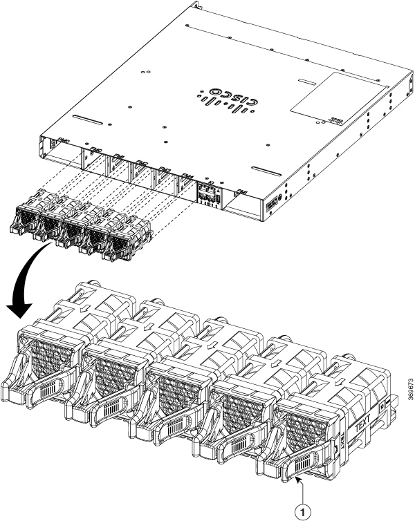
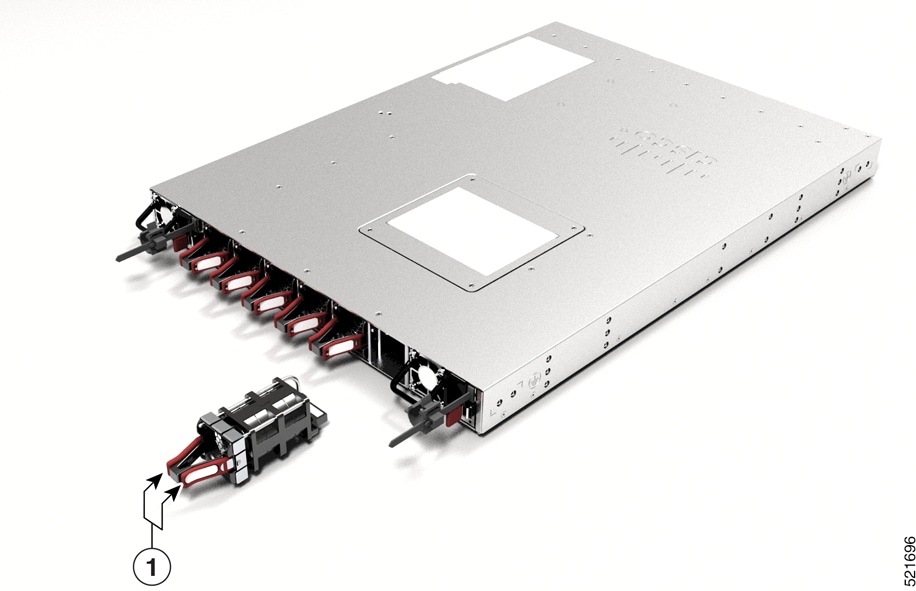
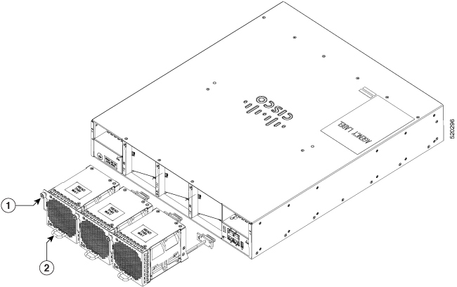
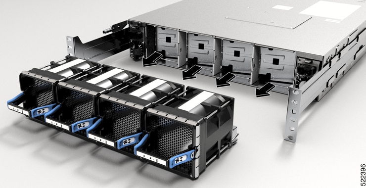
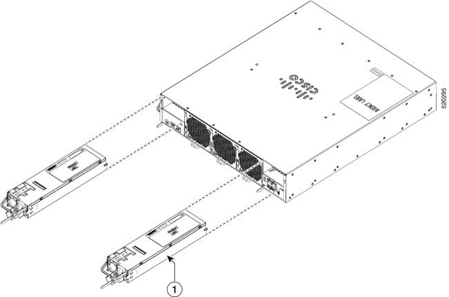
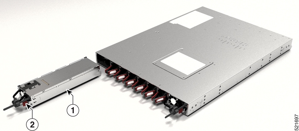
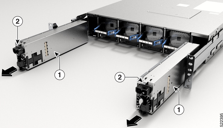
Replace the Latched Fan Modules
 Warning |
Statement 1090—Installation by Skilled Person Only a skilled person should be allowed to install, replace, or service this equipment. See statement 1089 for the definition of a skilled person. There are no serviceable parts inside. To avoid risk of electric shock, do not open. |
Warning |
Statement 1091—Installation by an Instructed Person Only an instructed person or skilled person should be allowed to install, replace, or service this equipment. See statement 1089 for the definition of an instructed or skilled person. There are no serviceable parts inside. To avoid risk of electric shock, do not open. |
Warning |
Statement 1073—No User-Serviceable Parts There are no serviceable parts inside. To avoid risk of electric shock, do not open. |
This procedure is applicable for Cisco 8201, Cisco 8201-32FH, and Cisco 8201-24H8FH routers.
|
Router |
Fan Module |
PID |
|---|---|---|
|
Cisco 8201 |
Port-side intake airflow |
FAN-1RU-PI |
|
Port-side exhaust airflow |
FAN-1RU-PE |
|
|
Cisco 8201-32FH and Cisco 8201-24H8FH |
Port-side intake airflow |
FAN-1RU-PI-V2 |
|
Port-side exhaust airflow |
FAN-1RU-PE-V2 |
 Note |
The airflow direction must be the same for all power supply and fan modules in the chassis. |
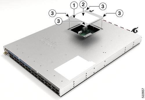
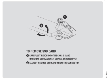
Procedure
|
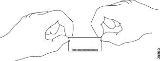
Step 1 |
To remove a fan module, follow these steps:
|
||||
|
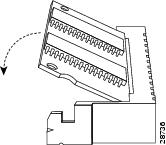
Step 2 |
To install a fan module, follow these steps: |

 Feedback